VPN-1
®
/FireWall-1
®
• Introducing the BIG-IP and Check Point
VPN-1/FireWall-1 LB, HALB, VPN, and ELA
configurations
• Configuring the BIG-IP and Check Point FireWall-1
for firewall load balancing (LB)
• Configuring the BIG-IP and VPN-1/FireWall-1 for
high availability firewall load balancing (HALB)
• Configuring the BIG-IP and VPN-1 for load
balancing VPN traffic
• Enabling logging to the Check Point management
station
Introducing the BIG-IP and Check Point VPN-1/FireWall-1
LB, HALB, VPN, and ELA configurations
With the BIG-IP product family, you can set up firewall load balancing or high availability firewall load balancing for the Check Point FireWall-1. Firewall load balancing (LB) allows you to load balance inbound and outbound traffic in a multiple firewall setup. High availability load balancing (HALB) uses the VPN-1/FireWall-1 state-sharing capabilities to ensure that all active connections, including VPN, are not lost in the event of a failover from a load balancing gateway to the remaining load balancing gateways. This document includes the following sections:
◆ Detailed procedures on how to setup the BIG-IP and VPN-1/FireWall-1
for firewall load balancing (LB).
◆ Detailed procedures on how to setup the BIG-IP and VPN-1/FireWall-1
for high availability (HALB) firewall load balancing.
◆ Detailed procedures on how to setup the BIG-IP and VPN-1/FireWall-1
to load balance VPN traffic.
◆ Detailed procedures on how to setup the BIG-IP, VPN-1/FireWall-1, and
the F5 Event Logging API (ELA) proxy applet for event notification.
Configuring the BIG-IP and Check Point FireWall-1 for
firewall load balancing (LB)
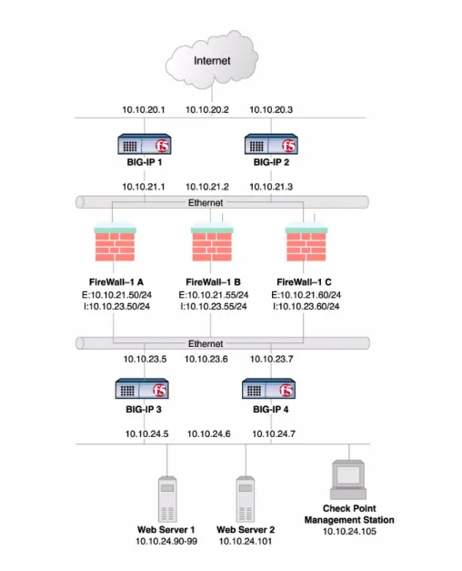
For both LB and HALB, please refer to Figure 1.1 for our example network setup.
On both the external BIG-IP units and the internal BIG-IP units, you need to complete the following procedures. The documentation takes you through these procedures first for the external BIG-IP, and then the internal BIG-IP. • Create a firewall pool
• Create virtual servers
• Enable UDP on global port any/0 • Turn off the default ICMP monitors • Create and apply firewall monitors
• Configure VLAN failsafe on the virtual servers • Synchronize the BIG-IP configuration
To configure the FireWall-1 for LB, you need to complete the following tasks in order:
• Define workstation objects • Define group objects
• Create a monitor service using TCP port 684 • Create a firewall rule
Configuring the BIG-IP for two-way firewall load balancing
Two-way firewall load balancing is appropriate for any enterprise that wants to provide information by way of the Internet, while limiting traffic to a specific service, and also wants to maintain a large intranet with fast access to the Internet for internal users.
This configuration calls for two BIG-IP redundant systems, each composed of the following units:
◆ A BIG-IP unit on the outside (that is, the side nearest the Internet) of the
firewalls, to balance traffic inbound across the firewalls.
◆ A BIG-IP unit on the inside (that is, the side nearest the intranet) of the
firewalls to balance traffic outbound across the firewalls, and also to balance traffic inbound across the server array.
Collectively, this is known as a firewall sandwich configuration, because the BIG-IP units are on either side of the firewalls, sandwiching them. Figure 1.1 illustrates this type of configuration, and provides an example configuration for this entire chapter. Remember that this is just a sample: when creating your own configuration, you must use IP addresses, host names, and so on, that are applicable to your own network.
Note
For more information about BIG-IP concepts and features discussed in this solution, please refer to the BIG-IP Reference Guide.
Note
This configuration requires that you have BIG-IP version 4.5.10 OPSECTM
Build or later installed on the BIG-IP redundant pairs. The OPSEC Build is available from the AskF5 site http://tech.f5.com. Download and installation instructions can be found inSolution1120.
Figure 1.1 A firewall sandwich configuration using Check Point VPN-1® GatewayTM/FireWall-1
Configuring the external BIG-IP
The following step-by-step procedures take you through configuring one of the external BIG-IP units that sits between the Internet and the FireWall-1 modules and synchronizing it with its peer. So, this means that you create the full configuration on one unit and then you synchronize, or push out, the
configuration to the other unit in the redundant pair. The external BIG-IP units sit between the Internet and the firewalls. The external BIG-IP units load balance incoming traffic to the firewalls, and forward internal client responses outbound. In Figure 1.1, the external BIG-IP units are labeled BIG-IP 1 and BIG-IP 2.
Creating pools on the external controller
To use the configuration outlined in this document, you must create a load balancing pool. In this example, the members of the pool are the firewalls through which you want to load balance incoming traffic. A load balancing pool is a set of network devices grouped together to receive traffic according to the load balancing method. You will need to provide a name for each pool, and add the resources for each (the IP addresses and the TCP/UDP service).
To create the external firewall pool
1. In the navigation pane, click Pools.The Pools screen opens. 2. Click the Add button.
The Add Pool screen opens.
3. On the Add Pools screen, type the name ext_fw_pool.
4. In the Resources section, type the external IP address for the first FireWall-1 in the Member Address box. For our example, type:
10.10.21.60
5. In the Service box, type 684. This allows the pool to handle 684 monitor traffic for any service.
6. Click the Move (>>) button to add the member to the Current Members box.
7. Repeat steps 2 through 4 for the other two FireWall-1 external IP addresses and services. In our example, these are:
10.10.21.55:684 10.10.21.50:684
8. When all three IP addresses display in the Current Members box, click the DONE button.
The Add Pool screen closes and the pool you created is displayed in the table on the Pools screen.
To configure persistence mode
You need to configure persistence on the external firewall pool. This ensures that connections established for a client through a particular firewall remain routed through that firewall. The example in this document uses simple persistence.
1. Click the name ext_fw_pool to open the Pool Properties screen for this pool.
2. Click the Persistence tab to open the Persistence screen. 3. From the Persistence Type choices, select Simple. 4. Type a Timeout of 60 seconds.
5. Click the Apply button.
Creating a wildcard virtual server
The next step is to create a wildcard virtual server. The wildcard virtual server is used by the BIG-IP to forward traffic that does not match another virtual server in the configuration outbound toward the Internet. In this configuration, the wildcard virtual server performs similarly to a default gateway.
To create a wildcard virtual server
1. In the navigation pane, click Virtual Servers. The Virtual Servers screen opens.
2. Click the Add button.
The Add Virtual Server screen opens.
3. In the Address box, type the wildcard virtual IP address.
0.0.0.0
4. In the Service box, type the service 0 or any. 5. Click NEXT.
The Configure Basic Properties screen opens.
6. Clear the Enable Address Translation check box to disable address translation.
7. Clear the Enable Port Translation check box to disable port translation.
8. In the VLANs section, click external to highlight it, and then click the Move (>>) button.
The external VLAN now appears in the Disabled box. 9. Click NEXT.
10. Choose Forwarding, and click NEXT.
The Configure Outbound Properties screen opens. 11. Check the Mirrored Connections box to enable mirrored
connections.
12. For the last hop pool, choose the ext_fw_pool, and click NEXT. The Configure Redundant Properties screen opens.
13. Click DONE.
The Virtual Servers screen opens and displays your newly created virtual server.
Creating network virtual servers for inbound traffic
After you define the firewall load balancing pool (ext_fw_pool), you can define virtual servers on the BIG-IP to load balance inbound connections through its members. A virtual server is an IP address that is visible to clients. It is a routable entity through which network devices in a pool are made available. The role of the virtual server on the external BIG-IP pair is to load balance incoming traffic to the FireWall-1 modules. In this example, the firewalls are performing network address translation (NAT) for the internal resources. To support this, you must create a network virtual server using the firewall’s external network IP that will load balance traffic across the pool of external interfaces of the firewalls (ext_fw_pool).
Note
You can also configure a virtual server with any IP load balancing if you want to restrict traffic to specific types. For more information, refer to the BIG-IP Reference Guide.
To create a network virtual server
1. In the navigation pane, click Virtual Servers. The Virtual Servers screen opens.
2. Click the Add button.
The Add Virtual Server wizard opens to the Configure Virtual IP Address and Service screen.
3. On the Configure Virtual IP Address and Service screen:
• In the Address box, type the virtual IP address. For our example, this is 10.10.21.0.
• In the Service box, type the TCP service 0 or any. This allows the virtual server to support most types of traffic.
4. Click NEXT.
5. Clear the Enable Address Translation check box to disable address translation.
6. Clear the Enable Port Translation check box to disable port translation.
7. Click NEXT.
The Select Physical Resources screen opens.
8. In the Select Physical Resources screen, choose Pool, and from the list, select the firewall pool you created, ext_fw_pool.
9. Click NEXT.
The Configure Redundant Properties screen opens. 10. Check the Mirrored Connections box to enable mirrored
connections. 11. Click DONE.
The Virtual Servers screen opens and displays your newly created virtual server.
Enabling UDP on service any/0
When you create the virtual server using the wildcard service any (or 0), you also create an associated global virtual service. This allows the BIG-IP to load balance UDP traffic. Note that TCP service is enabled by default when you associate the node with the pool. After you enable UDP, set the UDP timeout from the command line.
To enable UDP on the global virtual service any/0
1. In the navigation pane, click Virtual Servers.2. Click the Virtual Services tab to open the Virtual Service Properties screen.
3. In the Virtual Service column, find the 0 service. Check the UDP Enabled column. If there is a green status light in the column, UDP is already enabled. However, if there is a red status light in the column, continue to step 4.
4. Click 0 in the Virtual Service row.
The global properties screen for the 0 port opens. 5. Click the UDP Enabled check box.
6. Click the Apply button to enable UDP. The screen does not change.
7. Click the Return to Global Virtual Service List button to return to the Global Virtual Port screen, and verify that the 0 service has UDP enabled on it.
To set the global UDP timeout from the command line
After you enable UDP on the global virtual service, set the global timeout to 30 seconds. To do this, add the timeout to the services section of the bigip.conf file using the following procedure.
1. On the BIG-IP, type the following command:
cd /config
2. To edit the file using the pico editor, type the following command:
pico bigip.conf
3. In the services section, add the following line:
service * timeout udp 30
4. Save the file, and exit to the command prompt.
5. Type the following command to reload the BIG-IP configuration:
b load
Turn off the default ICMP monitor
Before you set up a transparent monitor to check the connections through the FireWall-1 modules, you must turn off the ICMP monitor. The BIG-IP uses ICMP monitors to verify the availability network devices configured as members of load balancing pools. The basic ICMP monitors are created by default for each member added to a pool. Since the basic ICMP monitor does not determine when a FireWall-1 module is not passing traffic (such as during a service failure), you must turn them off for the configuration described in this document. To turn them off, use the following procedure.
WARNING
These steps remove all ICMP monitor associations that were created by default. If you require specific nodes, such as members of a server array to be monitored with ICMP, you must specifically associate an ICMP monitor with the nodes you want monitored before you complete these steps.
Turning off the default ICMP monitors
1. In the navigation pane, click Monitors. The Monitors screen opens.
2. From the Choose Monitor list, select ICMP and click the Move button (>>).
3. The monitor appears in the Monitor Rule box.
4. In the Node Address section of the screen, check the Del box for the existing * association.
Creating and associating monitors
After you remove the default ICMP monitors, you need to create a user-defined monitor to monitor the status of each FireWall-1 module’s connections and services. The monitor that does this sends a test string from the external BIG-IP through the FireWall-1 modules to the internal BIG-IP pair. If the monitor cannot confirm that port 684 is available through one of the firewalls it is monitoring, the BIG-IP stops sending traffic through that firewall.
Note
If you choose not to use port 684, you need to change the monitor definition accordingly. Refer to the BIG-IP Reference Guide for more information.
To create a firewall monitor
1. In the navigation pane, click Monitors. 2. On the Monitors screen, click the ADD button.
The Add Monitor wizard opens.
3. On the Configure Monitor Name and Parent screen, type the name ext_fw_mon.
4. From the Inherits From list, select tcp, and click NEXT. The Configure Basic Properties screen opens.
5. On the Configure Basic Properties screen, leave the default interval (5) and timeout (16), and click NEXT.
The Configure ECV TCP Monitor screen opens. 6. Check the Transparent box, and click NEXT.
The Configure Destination Address and Service (Alias) screen opens.
7. In the Destination IP box, type the shared IP address of the internal pair of BIG-IP units. In this example, the IP address you type is 10.10.23.6.
8. In the Destination Service box, type 684. 9. Click DONE.
The Add Monitor wizard closes, and the new monitor is listed in the User Defined column.
To associate a monitor with a node
Once you create a monitor, you need to associate it with a node to monitor. 1. On the navigation pane, click Monitors to open the Monitors
2. Click the Node Associations tab to open the Node Associations screen.
3. From the Choose Monitor list, select ext_fw_mon (or the name you gave the transparent TCP monitor), and click the Move (>>) button.
The monitor appears in the Monitor Rule box.
4. In the Associate Current Monitor Rule column, check the box in the row of the node to which you want to associate this monitor. For our example, you check the box for 10.10.21.50, 10.10.21.55, and 10.10.21.60.
5. Click the Apply button.
Configuring VLAN failsafe
For maximum reliability, the BIG-IP supports failure detection on both internal and external VLANs. When you arm the failsafe option on a VLAN, the BIG-IP monitors network traffic going through the VLAN. If the BIG-IP detects a loss of traffic on an VLAN when half of the fail-safe timeout has elapsed, it attempts to generate traffic. A VLAN attempts to generate network traffic by issuing ARP requests to nodes accessible through the VLAN. Also, an ARP request is generated for the default route if the default router is accessible from the VLAN. Any traffic through the VLAN, including a response to the ARP requests, averts a failover.
If the BIG-IP does not receive traffic on the VLAN before the timer expires, it initiates a failover, switches control to the standby unit, and reboots.
To arm failsafe on a VLAN using the Configuration utility
1. In the navigation pane, click Network.
The VLANs list opens and displays all VLANs. 2. Select a VLAN name.
The VLAN Properties screen opens. 3. To arm failsafe, check Arm Failsafe.
To disarm failsafe, clear the Arm Failsafe box.
4. If you are arming failsafe, in the Timeout box, type the maximum time allowed for a loss of network traffic before a failover occurs. 5. Click the Apply button.
Configuration Note
You should arm VLAN failsafe on both the internal and external VLANs.
Synchronizing the external BIG-IP redundant system
Now that you have completely configured one external BIG-IP, you synchronize it with its peer for failover purposes. The synchronization process pushes the configuration from the system you configured to the peer system in the redundant pair.
To synchronize the BIG-IP units
1. On the navigation pane, click System.The System screen opens.
2. Click the Redundant Properties tab to open the Redundant Properties screen.
3. Click the Synchronize Configuration button.
Configuring the internal BIG-IP
Once you have configured the external BIG-IP redundant pair (Figure 1.1 BIG-IP 1 and BIG-IP 2), you can configure the internal BIG-IP redundant pair (Figure 1.1 BIG-IP 3 and BIG-IP 4). Many of the steps are the same, but use different values.
Creating the load balancing pool on the internal BIG-IP pair
To use the configuration outlined in this document, you must create a load balancing pool on the internal BIG-IP pair. In this example, the members of the pool are the firewalls through which you want to load balance outbound traffic. A load balancing pool is a set of network devices grouped together to receive traffic according to the load balancing method. You will need to enter a name for each pool, and add the resources for each (the IP addresses and the TCP/UDP service).
To create the internal firewall pool
1. In the navigation pane, click Pools.The Pools screen opens. 2. Click the Add button.
The Add Pool screen opens.
3. On the Add Pools screen, type the name int_fw_pool.
4. In the Resources section, type the internal IP address for the first FireWall-1 in the Member Address box. For our example, type:
10.10.23.60
5. In the Service box, type 684.
6. Click the Move (>>) button to add the member to the Current Members box.
7. Repeat steps 2 through 6 for the other two FireWall-1 internal IP addresses and services. In our example, these are:
10.10.23.55:684 10.10.23.50:684
8. When all three IP addresses display in the Current Members box, click the DONE button.
The Add Pool screen closes, and the Pools screen displays the new firewall pool in the table.
To configure persistence mode
You need to configure persistence on the internal firewall pool. This ensures that connections established for a client through a particular firewall remain routed through that firewall. The example in this document uses simple persistence.
1. Click the name int_fw_pool to open the Pool Properties screen for this pool.
2. Click the Persistence tab to open the Persistence screen. 3. From the Persistence Type choices, select Simple. 4. Type a Timeout of 60 seconds.
5. Click the Apply button.
Creating a wildcard virtual server
The next step is to create a wildcard virtual server. The wildcard virtual server allows clients on the internal side of the network to connect to network devices on the other side of the internal BIG-IP redundant pair through the FireWall-1 modules. For example, this is useful when the BIG-IP redundant pair does not have a specific virtual server match for a destination IP address of the client, the BIG-IP matches the client’s IP address to a wildcard virtual server. The BIG-IP then forwards the traffic to a member of the pool associated with the wildcard virtual server. In our example, this is the pool of FireWall-1 modules. To do this, create a wildcard virtual server that accepts all traffic from the internal network, and then load balances the traffic through the firewalls.
To create a wildcard virtual server
1. In the navigation pane, click Virtual Servers. The Virtual Servers screen opens.
2. Click the Add button.
The Add Virtual Server screen opens.
3. In the Address box, type the wildcard virtual IP address.
4. In the Service box, type the service 0 or any. 5. Click NEXT.
The Configure Basic Properties screen opens.
6. Clear the Enable Address Translation check box to disable address translation.
7. Clear the Enable Port Translation check box to disable port translation.
8. In the VLANs section, click external to highlight it, and then click the Move (>>) button.
The external VLAN now appears in the Disabled box. 9. Click NEXT.
The Select Physical Resources screen opens.
10. Choose Pool, and from the list, select the firewall pool you created, int_fw_pool.
11. Click NEXT.
The Configure Redundant Properties screen opens. 12. Check the Mirrored Connections box to enable mirrored
connections. 13. Click DONE.
The Virtual Servers screen opens and displays your newly created virtual server.
Creating virtual servers for inbound traffic
You create two forwarding virtual servers for this configuration. A forwarding virtual server, unlike the network virtual server created in previous steps, does not use an associated pool to load balance traffic. Instead, traffic is transparently forwarded out the proper interface. In this example the internal BIG-IP redundant pair needs to route traffic between its internal network (10.10.24.0) and the external network (10.10.23.0). Without these virtual servers, traffic originating from one of these networks destined for the other would not be routed correctly. This is accomplished by creating two forwarding virtual servers.
To create forwarding virtual servers
1. In the navigation pane, click Virtual Servers. The Virtual Servers screen opens.
2. Click the Add button.
The Add Virtual Server screen opens.
3. In the Address box, type the virtual IP address. For our example, this is 10.10.24.0.
4. In the Service box, type the TCP service 0 or any. 5. Click NEXT.
The Configure Basic Properties screen opens. Make no changes to this screen.
6. Clear the Enable Address Translation check box to disable address translation.
7. Clear the Enable Port Translation check box to disable port translation.
8. Click NEXT.
The Select Physical Resources screen opens. 9. Select Forwarding.
10. Click NEXT.
The Configure Outbound Properties screen opens.
11. For the last hop pool, choose the int_fw_pool, and click NEXT. The Configure Redundant Properties screen opens.
12. Check the Mirrored Connections box to enable mirrored connections.
13. Click DONE.
The Virtual Servers screen opens and displays your newly created virtual server.
14. Repeat steps 2 through 9 using the IP address 10.10.23.0 in step 3. However, do not configure the last hop pool.
Enabling UDP on service any/0
When you create the virtual server using the wildcard service any (or 0), you also create an associated global virtual service. This allows the BIG-IP to load balance UDP traffic. Note that TCP service is enabled by default when you associate the node with the pool. After you enable UDP, set the timeout from the command line.
To enable UDP on the global virtual service any/0
1. In the navigation pane, click Virtual Servers.2. Click the Virtual Services tab to open the Virtual Service Properties screen.
3. In the Virtual Service column, find the 0 service. Check the UDP Enabled column. If there is a green status light in the column, UDP is already enabled. If there is a red status light in the column, continue to step 4.
4. Click 0 in the Virtual Service row.
5. Click the UDP Enabled check box. 6. Click the Apply button to enable UDP.
The screen does not change.
7. Click the Return to Global Virtual Service List button to return to the Virtual Port screen, and verify that the 0 service has UDP enabled on it.
To set the global UDP timeout from the command line
After you enable UDP on the global virtual service, set the global timeout to 30 seconds. To do this, add the timeout to the services section of the bigip.conf file using the following procedure.
1. On the BIG-IP, type the following command:
cd /config
2. To edit the file using the pico editor, type the following command:
pico bigip.conf
3. In the services section, add the following line:
service * timeout udp 30
4. Save the file and exit to the command prompt.
5. Type the following command to reload the BIG-IP configuration:
b load
Turn off the default ICMP monitor
Before you set up a transparent monitor to check the connections through the FireWall-1 modules, you must turn off the ICMP monitor. The BIG-IP uses ICMP monitors to verify the availability network devices configured as members of load balancing pools. The basic ICMP monitors are created by default for each member added to a pool. Since the basic ICMP monitor does not determine when a FireWall-1 module is not passing traffic (such as during a service failure), you must turn them off for the configuration described in this document. To turn them off, use the following procedure.
WARNING
These steps remove all ICMP monitor associations that were created by default. If you require specific nodes, such as members of a server array to be monitored with ICMP, you must specifically associate an ICMP monitor with the nodes you want monitored before you complete these steps.
Turning off the default ICMP monitors
1. In the navigation pane, click Monitors.The Monitors screen opens.
2. From the Choose Monitor list, select ICMP and click the Move button (>>).
The monitor appears in the Monitor Rule box.
3. In the Node Address section of the screen, check the Del box for the existing * association.
4. Click the Apply button.
Creating and associating monitors
After you remove the default ICMP monitors, you need to create a user-defined monitor to monitor the status of each FireWall-1 module’s connections and services. The monitor that does this sends a test string from the internal BIG-IP through the FireWall-1 modules to the external BIG-IP pair.
To create a firewall monitor
1. In the navigation pane, click Monitors. 2. On the Monitors screen, click the ADD button.
The Add Monitor wizard opens.
3. On the Configure Monitor Name and Parent screen, type the name int_fw_mon.
4. From the Inherits From list, choose tcp, and click NEXT. The Configure Basic Properties screen opens.
5. On the Configure Basic Properties screen, leave the default interval (5) and timeout (16) and click NEXT.
The Configure ECV TCP Monitor screen opens. 6. Check the Transparent box, and click NEXT.
The Configure Destination Address and Service (Alias) screen opens.
7. In the Destination IP box, type the shared IP address of the external pair of BIG-IP units. In this example, the IP address you would type is: 10.10.21.2. In the Destination Service box, type 684.
8. Click DONE.
The Add Monitor wizard closes, and the new monitor is listed in the User Defined column.
To associate a monitor with a node
Once you create a monitor, you need to associate it with a node to monitor. 1. On the navigation pane, click Monitors to open the Monitors
screen.
2. Click the Node Associations tab to open the Node Associations screen.
3. From the Choose Monitor list, select int-fw-mon (or the name you gave the transparent TCP monitor), and click the Move (>>) button. The monitor appears in the Monitor Rule box.
4. In the Associate Current Monitor Rule column, check the box in the row of the node to which you want to associate this monitor. For our example, you check the box for 10.10.23.50, 10.10.23.55, and 10.10.23.60.
5. Click the Apply button.
Configuring VLAN failsafe
For maximum reliability, the BIG-IP supports failure detection on both internal and external VLANs. When you arm the failsafe option on a VLAN, the BIG-IP monitors network traffic going through the VLAN. If the BIG-IP detects a loss of traffic on an VLAN when half of the fail-safe timeout has elapsed, it attempts to generate traffic. A VLAN attempts to generate network traffic by issuing ARP requests to nodes accessible through the VLAN. Also, an ARP request is generated for the default route if the default router is accessible from the VLAN. Any traffic through the VLAN, including a response to the ARP requests, averts a failover.
If the BIG-IP does not receive traffic on the VLAN before the timer expires, it initiates a failover, switches control to the standby unit, and reboots.
To arm failsafe on a VLAN using the Configuration utility
1. In the navigation pane, click Network.
The VLANs list opens and displays all VLANs. 2. Select a VLAN name.
The VLAN Properties screen opens. 3. To arm failsafe, check Arm Failsafe.
To disarm failsafe, clear the Arm Failsafe box.
4. If you are arming failsafe, in the Timeout box, type the maximum time allowed for a loss of network traffic before a failover occurs. 5. Click the Apply button.
Configuration Note
Synchronizing the BIG-IP redundant system
Now that you have completely configured one internal BIG-IP, you synchronize it with its peer for failover purposes. The synchronization process pushes the configuration from the system you configured to the peer system in the redundant pair.
To synchronize the BIG-IP units
1. In the navigation pane, click System.2. Click the Redundant Properties tab to open the Redundant Properties screen.
3. Click the Synchronize Configuration button.
Configuring the Check Point VPN-1/FireWall-1 for Load Balancing
All of the configurations described in this chapter are done from the Check Point FireWall-1 management station using the Visual Policy EditorTM or
configuration application as noted, and not on the BIG-IP. To configure the FireWall-1 security policy, you must complete the following tasks: • Define workstation objects
• Define group objects
• Create a monitor service using TCP port 684 • Create a firewall rule
• Configure Network Address Translation (NAT)
Note
This document assumes that you have installed and configured the
FireWall-1 modules to communicate with the firewall management station. Also, all network routes must be defined in the NT routing table.
For outbound traffic, all the firewall gateways should be routed to the internal IP alias of the external BIG-IP redundant pair (10.10.21.2 in this example). For inbound traffic, all the firewalls should use internal BIG-IP redundant pair’s external IP alias as the gateway to the internal network (10.10.23.6 in this example).
For additional information about these settings, consult the Check Point 2000 NG documentation Administration Guide provided by Check Point.
Defining each BIG-IP as a workstation object
The first task you need to complete for the Check Point VPN-1/FireWall-1 to support the firewall monitors (int_fw_mon and ext_fw_mon) you created on the BIG-IP, is to define each BIG-IP, and the shared floating IP alias of each redundant pair as a workstation object in the FireWall-1 Policy Editor.
When you define the workstation objects, use the BIG-IP addresses for the network directly connected to the FireWall Module, including the shared floating IP addresses for each BIG-IP redundant pair. For example, for the internal BIG-IP redundant pair, use the external IP addresses. For the external BIG-IP redundant pair, use the internal IP addresses.
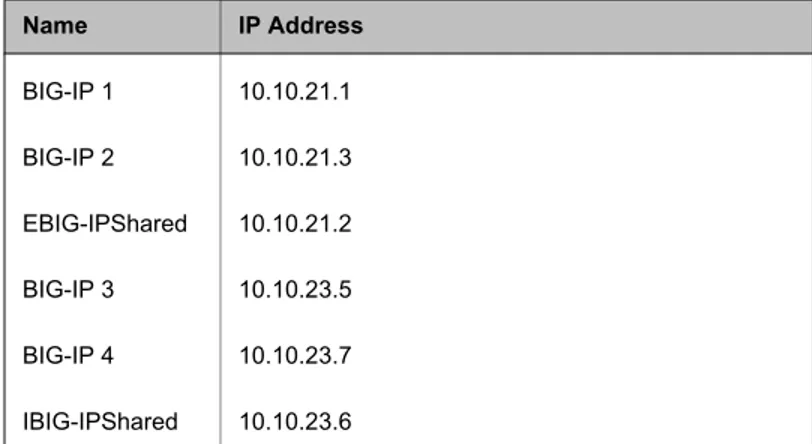
For our example, create workstation objects for each of the IP addresses in the following table.
To define BIG-IP workstation objects in the Check Point
FireWall-1 Smart Dashboard
1. From the Check Point FireWall-1 Policy Editor menu, choose Manage and then point to Network Objects.
The Network Objects dialog box opens. 2. Click the New button, then select Node->Host.
The Host Node dialog box opens (Figure 1.3).
3. Type the name of one object and its IP address in the appropriate boxes.
4. Repeat steps 1 through 3 for all six BIG-IP objects listed in Table 1.1. The IP addresses of the objects listed in this table are based on the example in this documentation.
Name IP Address
BIG-IP 1 10.10.21.1 BIG-IP 2 10.10.21.3 EBIG-IPShared 10.10.21.2 BIG-IP 3 10.10.23.5 BIG-IP 4 10.10.23.7 IBIG-IPShared 10.10.23.6
Figure 1.2 Host Node dialog box
Defining Group objects with the Workstation objects
The second task in configuring the Check Point VPN-1/FireWall-1 to support the firewall monitors (int_fw_mon and ext_fw_mon) you created on the BIG-IP is to create two group objects that include the appropriate Workstation objects you created for the BIG-IP redundant pairs. You can use group objects to organize network objects for rule administration.
To define BIG-IP group objects in the Check Point FireWall-1
Policy Editor
1. From the Check Point FireWall-1 Policy Editor menu, choose Manage and then point to Network Objects.
2. Click the New button, then choose Group->Simple Group. The Group Properties dialog box opens (Figure 1.3). 3. Type the name of the group object.
4. Select the Objects you just made.
5. Click the Add button to add the BIG-IP workstation objects to the group object.1.1.
For our example, you need to make two group objects:
• One group, named EBIG-IP, contains the two external BIG-IP objects and the external BIG-IP shared floating IP alias object. • One group, named IBIG-IP, contains the two internal BIG-IP objects and the internal BIG-IP shared floating IP alias object.
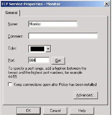
Creating a monitor service
The next step for configuring the FireWall-1 to support the firewall monitors (int_fw_mon and ext_fw_mon) that you created on the BIG-IP is to define the monitor service in the Check Point Policy Editor.
To create the monitor service to support the BIG-IP firewall
monitors
1. In the Check Point FireWall-1 Policy Editor menu, choose Manage and then point to Services.
2. Click New, and then select TCP.
The TCP Service Properties dialog box opens (Figure 1.3). 3. Assign the monitor service a name and specify port 684.
You can name the service anything you want. For our example, we use Monitor. In the Port box, type 684.
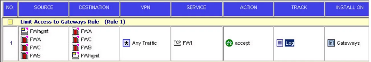
Creating a Firewall Rule
The final task required to configure the FireWall-1 to support the firewall monitors (int_fw_mon and ext_fw_mon) you created on the BIG-IP is to create a firewall rule that allows health monitor checks between the external and internal BIG-IP redundant pairs using the group objects and monitor service you created in the previous steps. Figure 1.5 is an example of the firewall rule you would create using the BIG-IP and firewall configuration example in Figure 1.1, on page 1-3. After you create the rule, install the policy on all FireWall Modules.
Figure 1.5 Monitor Rule
Configuring Network Address Translation (NAT) on the FireWall-1 module
In this document, we are assuming that the FireWall-1 modules are performing network address translation (NAT) for internal resources. The BIG-IP configuration outlined in this document supports both static NAT or hide NAT. You can configure either type of NAT using the NAT tab in the network object properties dialog box in the Check Point Policy Editor. To support high availability of FireWall-1/VPN-1 connections that are address translated using dynamic or hide mode, choose a unique IP rather than an IP address of a firewall. In addition to completing the NAT tab, static NATs require you to add a permanent static route on each FireWall-1 module to route the NAT IP address assigned to the external shared IP address of the internal BIG-IP redundant pair.
For example, in Figure 1.1 you configure the firewalls with a static NAT for Web Server 2. For simplicity, we select the IP address 10.10.21.101 and complete the NAT tab for Web Server 2 on the Network Object properties screen and then apply the policy to the firewall modules. You can choose any IP address on the firewall’s external network that is available to translate the Web Server 2 address.
The final step is to configure a permanent static route on each firewall.
To apply a static route on a firewall module
Complete these tasks to configure a static route on each firewall module. 1. Click Start, then click Run.
2. In the Open box, type cmd. 3. Click OK.
The Windows Command prompt opens.
4. At the prompt, use the route command to add a static route. This is the syntax for the route command:
route add destination mask subnetmask gateway metric costmetric if interface
where:
For example, to add a static route to the 10.0.0.0 network that uses a subnet mask of 255.0.0.0, a gateway of 192.168.0.1, and a cost metric of 2, you type the following at a command prompt:
route add 10.0.0.0 mask 255.0.0.0 192.168.0.1 metric 2
Note
To make a static route persistent, you can either enter route add commands in a batch file that is run during system startup or use the -p option when adding routes. Routes added by using the -p option are stored in the Windows 2000 registry under the following key:
HKEY_LOCAL_MACHINE\SYSTEM\CurrentControlSet\Services\Tcpi p \Parameters\PersistentRoutes
All symbolic names used for destination or gateway are looked up in the network and computer name database files (Networks and Hosts), which are stored in the local systemroot\System32\Drivers\Etc folder. If a route addition fails, you can use the tracert command to verify that the gateway specified is directly reachable from the same subnet as this computer.
destination Specifies either an IP address or host name for the network or host.
subnetmask Specifies a subnet mask to be associated with this route entry. If subnetmask is not specified, 255.255.255.255 is used.
gateway Specifies either an IP address or host name for the gateway or router to use when forwarding. costmetric Assigns an integer cost metric (ranging from 1 through 9,999) to be used in calculating the fastest,
most reliable, and/or least expensive routes. If costmetric is not specified, 1 is used.
interface Specifies the interface to be used for the route that uses the interface number. If an interface is not specified, the interface to be used for the route is determined from the gateway IP address.
Repeat this procedure on each FireWall Module.
Note
You should not apply network address translation to the internal BIG-IP redundant pair or the firewall monitors will not function properly.
Note
For additional information about these settings, consult the vVG AI (Check Point 2000 Suite) Administration Guide provided by Check Point.
Configuring the BIG-IP and VPN-1/FireWall-1 for high
availability firewall load balancing (HALB)
The BIG-IP uses the VPN-1/FireWall-1 state sharing capabilities to ensure that all active connections, including VPN, are not lost in the event of a failover from a load balancing gateway to remaining active load balancing gateways.
Complete the following step-by-step procedures on both the internal and external BIG-IP redundant pairs.
The second part of this section describes how to configure the FireWall modules.
Configuring the BIG-IP units for HALB
This section describes how to configure the BIG-IP units for high availability.
To configure the BIG-IP units for HA, you must first complete the following tasks:
• Complete the configuration described in section Configuring the BIG-IP for two-way firewall load balancing, starting on page 1-2, with the following exceptions:
• Adjust the timeout values for both the ext_fw_mon and int_fw_mon to a default interval of 1 and an interval of 3. These adjustments increase the speed with which BIG-IP fails over connections from a failed node to a valid node. With these settings failover will occur within approximately four seconds. To verify the settings, refer to the screen shot below.
• Adjust the VLAN failsafe timeout values on both BIG-IP pairs to 10 seconds
• Enable dynamic connection rebinding on each firewall virtual server. • Synchronize the BIG-IP configurations.
Enabling dynamic connection rebinding
Dynamic connection rebinding is a feature for those virtual servers that are load balancing transparent devices such as firewalls or routers. Dynamic connection rebinding causes any connections that were made to a node address or service to be redirected to another node, if the original node transitions to a DOWN state. In this case, all connections to the failed node that were made through the virtual server are moved to a newly-selected node from the virtual server's pool. The new node is selected using the pool's load-balancing algorithm. You should enable dynamic connection rebinding on each virtual server in the firewall load balancing configuration.
To enable dynamic connection rebinding
1. Start the Configuration utility.
2. In the navigation pane, click Virtual Servers. 3. Select the IP address for the firewall virtual server.
This displays the Properties page for that server. 4. Check the Enable Connection Rebind check box. 5. Click the Apply button.
Configuration Note
You should enable dynamic connection rebinding for each virtual server configured for firewall load balancing. In this example, you enable dynamic connection rebinding on the following virtual servers for the external redundant BIG-IP pair:
0.0.0.0 (wildcard)
10.10.21.0 (network virtual server)
Enable dynamic connection rebinding for the following virtual servers on the internal redundant BIG-IP pair:
0.0.0.0 (wildcard virtual server) 10.10.24.0 (forwarding virtual server) 10.10.23.0 (forwarding virtual server)
Synchronizing the BIG-IP redundant system
Now that you have completed the additional steps for the HALB configuration, make sure you synchronize the configurations on both BIG-IP redundant pairs. The synchronization process pushes the configuration from the system you configured to the peer system in the redundant pair.
To synchronize the BIG-IP units
1. In the navigation pane, click System.2. Click the Redundant Properties tab to open the Redundant Properties screen.
3. Click the Synchronize Configuration button.
Configuring the Check Point FireWall-1 firewalls for HALB
The VPN-1/FireWall-1 provides stateful inspection even for stateless protocols such as UDP and RPC. To do this, the FireWall Module creates a virtual state for these connections and updates this state according to the data transferred. In addition, VPN-1/FireWall-1 maintains the state information for address translation and encryption. Different FireWall Modules running on different machines can synchronize their states. That is, they can share state information and can update each other with the different states of connections. When one FireWall Module stops functioning and another one takes its place, the second FireWall Module gateway has the latest state information for the connections. This means the firewall maintains the connections.
This section describes how to implement stateful synchronization between the FireWall Modules. To configure the FireWall-1 for HALB, you need to complete the following tasks in order:
• Complete the section Configuring the Check Point VPN-1/FireWall-1 for Load Balancing, starting on page 1-18.
• Enable gateway clusters. • Create a gateway cluster.
• Allow Synch service between firewalls.
• Create a rule to allow FW1Sync traffic between FireWall Modules. • Configure synchronization between firewalls modules. For more
information about this, refer to the Checkpoint configuration guide. • Create control paths between firewalls.
• Synchronize the time on all the firewalls and management stations.
Note
Mixing of 4.1 FireWall-1/VPN-1 and NG FireWall-1/VPN-1 modules in a single cluster is not supported.
Enabling gateway clusters
The first step to configuring the FireWall Modules to synchronize their FW1 tables is to enable gateway clusters. Gateway clusters are defined as a group of gateways with many properties in common. If one of the gateways fails, another gateway in the cluster takes over the connections from the failed gateway. Enabling gateway clusters allows you to create a gateway cluster object in the Policy Editor.
Note
All the gateways in a cluster must have the same operating system and same versions of the Check Point VPN-1/FireWall-1 software modules installed (version NG or later).
To enable gateway clusters
1. In the Policy Editor, click Policy. 2. Click Properties.
3. On the High Availability tab of the Properties Setup dialog box, check the Enable Gateway Clusters box.
4. All firewalls in the cluster should be enforcing the same security policy. To ensure this, check the box next to, Install Security Policy on a gateway cluster only if it can be successfully installed on all gateway cluster members. This ensures that all FireWall Modules enforce the same policy. This is required in a failover situation.
Creating a gateway cluster network object
The second step to configure the FireWall Modules to synchronize their FW1 tables is to create a gateway cluster network object with the Check Point Policy Editor. The gateway cluster option is only available in the Policy Editor after you enable gateway clusters. For more information, see
Enabling gateway clusters, on page 1-28.
To create a gateway cluster network object
1. In the Policy Editor, click Manage, then click Network Objects. 2. Click the New button.
3. From the menu, choose Gateway Clusters. The Gateway Clusters Properties dialog box opens.
4. Type a name for the cluster in the Name box. In this example, you would use the name fw_cluster.
5. Type an IP address for the cluster in the IP Address box. The IP address should be any valid unused IP address on the external network of the external BIG-IP. In the example in this document, base the IP address on the 10.10.20.0 network. In this example, the cluster IP address is 10.10.20.21. This IP address is used to support VPN resource access discussed in the section Configuring the BIG-IP and VPN-1 for load balancing VPN traffic, on page 1-32. 6. Click the OK button.
Defining the workstation objects as members of the gateway cluster
The next step in configuring the FireWall Modules to synchronize their FW1 tables is to add the FireWall Modules as members of the gateway cluster. To add a firewall member to a gateway cluster you must edit the firewall member object properties.
To define the workstation objects as members of the gateway
cluster
1. In the Policy Editor, click Manage, then click Network Objects. 2. Right-click a firewall object, and choose Edit.
The Workstation Properties dialog box opens.
3. In the General Tab, check the Member of Gateway Cluster box, and from the Member of Gateway Cluster list, select the gateway cluster.
4. Repeat steps 1 through 3 for each FireWall Module defined in the BIG-IP firewall pool (ext_fw_pool).
5. To view members of the gateway cluster, go to the Cluster Members tab on the properties dialog box for the Gateway Cluster object.
Creating a rule to allow FW1 traffic between firewalls.
The next step in configuring the FireWall-1 Modules to synchronize their FW1 tables is to create a rule to allow FW1 traffic between FireWall Modules. Create a rule that allows FW1 service traffic between all members of the gateway cluster you created with all of the BIG-IP workstation objects and apply it to the cluster (Figure 1.6).
Figure 1.6 An example of a FireWall-1 synchronization rule
Configuring synchronization between firewalls modules
For more information about this, refer to Checkpoint documentation. Navigate to Synchronization, the following window will appear:
Creating control paths between the FireWall Modules
After you configure synchronization between firewalls modules, you must establish a control path between each FireWall Module. To do this, use the fw putkey command on each FireWall Module to create a control path to the other FireWall Modules in the gateway cluster.
For information about how to use the fw putkey command, please refer to page 10 of the Check Point Reference Guide.
Synchronizing the time on all the firewalls and management stations
When using the Check Point cluster object for table synchronization, you must synchronize the time on all the firewalls and management stations. This ensures that all stateful connection is current if a FireWall Module fails over. If the time is not synchronized correctly, connections may be lost during failover.
Note
To confirm synchronization, compare the firewall connection tables by typing the following command:
fw tab -t connections
Note
If you use the external IP address of the firewall on the General tab of the firewall network object, the anti-spoofing feature in FireWall-1 drops packets when applying policies. To work around this issue, use the internal IP address of the firewall.
Verifying that connections survive failover
1. Open the Virtual Servers dialog.
2. Check Enable Connection Rebind in each virtual server. 3. Set System-> Advanced Properties->fastflow_active to off.
Configuring the BIG-IP and VPN-1 for load balancing VPN
traffic
The BIG-IP transparently load balances VPN traffic to VPN-1/FireWall-1 modules configured to use state sharing for VPN connections. The BIG-IP also provides failover of VPN sessions in the event of a service failure on a VPN-1 gateway.
In order to configure VPN-1 load balancing, you need to complete the BIG-IP redundant system configuration described in Configuring the BIG-IP units for HALB, starting on page 1-25, and complete a few additional tasks. These additional changes for the VPN HALB are for the external BIG-IP redundant pair only.
The first part of this section describes how you configure the external BIG-IP redundant pair for VPN load balancing.
The second part of this section describes two options for configuring the VPN-1 modules. The two options are single entry point (SEP) and gateway-to-gateway.
Configuring the BIG-IP systems for VPN-1 load balancing
This section describes how to configure the BIG-IP units for VPN load balancing.
To configure the BIG-IP units for VPN load balancing, you must first complete the following tasks:
◆ Complete the configuration described in section Configuring the BIG-IP units for HALB, starting on page 1-25. In addition to the configuration described in that section, complete the following tasks on the external BIG-IP redundant pair based on the encryption scheme you are using.
◆ If you are using IKE encryption scheme, follow the steps outlined in the
following bullets. For detailed configuration information, see
Configuring IKE encryption scheme support, on page 1-34. • Enable global persistence across all services.
• Create two virtual servers. Create one virtual server to direct traffic to the pool you create for encrypted key traffic, and one virtual server to route traffic destined for the firewall cluster IP.
• Enable the any IP feature and configure the any IP timeout on the wildcard virtual server 0.0.0.0:0 described in the section Configuring the external BIG-IP, on page 1-3. Also, enable the any IP feature and configure the any IP timeout on the two virtual servers that handle the encrypted key traffic to the firewall cluster, (10.10.20.21:500 and 10.10.20.21:0).
• Enable dynamic connection rebinding on the virtual servers 10.10.20.21:500, and 10.10.20.21:0.
• Enable UDP on port 500 for encrypted key traffic. • Apply the firewall monitor.
• Synchronize the BIG-IP configuration.
Figure 1.7 Example for setting up the BIG-IP and VPN-1/FireWall-1 modules for VPN load balancing
Configuring IKE encryption scheme support
The first step is to enable global persistence for all services. In order to guarantee that VPN key and tunnel traffic associated with the same transaction maintain connectivity to the same firewall module, it is necessary to enable global service persistence for all virtual servers.
To enable global persistence for all services
1. On the navigation pane, click System. The Global Properties Page opens. 2. Click the Advanced Properties tab.
The Advanced Properties screen opens.
3. Check the Allow persistence across all services for each virtual server box.
4. Click Apply.
Creating a virtual server for the encrypted key traffic
Create a virtual server for handling encrypted key traffic using the pool ext_fw_pool.
To create the virtual server for encrypted key traffic
1. In the navigation pane, click Virtual Servers.The Virtual Servers screen opens. 2. Click the Add button.
The Add Virtual Server screen opens. 3. In the Address box, type the IP address.
10.10.20.21
This is the firewall cluster IP address you created in the section
Enabling gateway clusters, on page 1-28. 4. In the Service box, type the service 500. 5. Click NEXT.
The Configure Basic Properties screen opens.
6. Clear the Enable Port Translation check box to disable port translation.
7. In the VLANs section, click internal to highlight it, and then click the Move (>>) button.
The internal VLAN now appears in the Disabled box. 8. Click NEXT.
9. Choose Pool, and from the list, select the pool ext_fw_pool. 10. Click NEXT.
The Configure Redundant Properties screen opens. 11. Check the Mirrored Connections box to enable mirrored
connections. 12. Click DONE.
The Virtual Servers screen opens and displays your newly created virtual server.
Creating a virtual server for the firewall cluster
Create a virtual server for the firewall cluster using the pool ext_fw_pool.
To create the virtual server for the firewall cluster
1. In the navigation pane, click Virtual Servers. The Virtual Servers screen opens.
2. Click the Add button.
The Add Virtual Server screen opens. 3. In the Address box, type the IP address.
10.10.20.21
This is the firewall cluster IP address you created in the section
Enabling gateway clusters, on page 1-28. 4. In the Service box, type the service 0. 5. Click NEXT.
The Configure Basic Properties screen opens.
6. Clear the Enable Port Translation check box to disable port translation.
7. In the VLANs section, click internal to highlight it, and then click the Move (>>) button.
The internal VLAN now appears in the Disabled box. 8. Click NEXT.
The Select Physical Resources screen opens.
9. Choose Pool, and from the list, select the pool ext_fw_pool. 10. Click NEXT.
The Configure Redundant Properties screen opens. 11. Check the Mirrored Connections box to enable mirrored
12. Click DONE.
The Virtual Servers screen opens and displays your newly created virtual server.
Enabling the any IP feature on the virtual server
After you create the configuration described in the section Configuring the external BIG-IP, on page 1-3, enable the any IP feature. Then, change the timeout setting on the wildcard virtual server 0.0.0.0, and on the virtual servers 10.10.20.21:500 and 10.10.20.21:0 on the external BIG-IP redundant pair.
To enable any IP in the Configuration utility
1. In the navigation pane, click Virtual Servers.2. Click the IP address of the virtual server you want to configure. The properties screen for the virtual server opens.
3. Click the Virtual Address Properties tab.
The Global Virtual Address Properties screen opens. 4. In the Any IP section, check the Enable box. 5. Change the timeout value to 5.
6. Click the Apply button. Configuration Note
You should enable the any IP feature for the following virtual servers on the external BIG-IP redundant pair:
10.10.20.21:500 (encrypted key traffic virtual server) 10.10.20.21:0 (cluster IP virtual server)
0.0.0.0:0 (wildcard virtual server)
Enabling dynamic connection rebinding on the virtual server for encrypted key traffic
Dynamic connection rebinding is a feature for those virtual servers that are load balancing transparent devices such as firewalls or routers. Dynamic connection rebinding causes any connections that were made to a node address or service to be redirected to another node, if the original node transitions to a DOWN state. In this case, all connections to the failed node that were made through the virtual server are moved to a newly-selected node from the virtual server's pool. The new node is selected using the pool's load-balancing algorithm. You should enable dynamic connection rebinding on each virtual server in the firewall load balancing configuration.
To enable dynamic connection rebinding
2. In the navigation pane, click Virtual Servers.
3. Select 10.10.20.21:500 for the firewall encrypted key virtual server. This displays the Properties page for the virtual server.
4. Check the Enable Connection Rebind box. 5. Click the Apply button.
6. Complete steps 1 through 5 for virtual server 10.10.20.21:0.
Enable UDP on port 500
In the configuration described in this section, you need to enable encrypted key traffic to pass on UDP port 500.
To enable UDP on the global virtual service any/0
1. In the navigation pane, click Virtual Servers.2. Click the Virtual Services tab to open the Global Virtual Service Properties screen.
3. In the Virtual Service column, find the 500 service. Check the UDP Enabled column. If there is a green status light in the column, UDP is already enabled. If there is a red status light in the column, continue to step 4.
4. Click 500 in the Virtual Service row.
The global properties screen for the 500 port opens. 5. Check the UDP Enabled box.
6. Click the Apply button to enable UDP. The screen does not change.
7. Click the Return to Global Virtual Service List button to return to the Global Virtual Port screen, and verify that the 500 service has UDP enabled on it.
Associating the external firewall monitor with the nodes in the encrypted key pool
After you remove the default ICMP monitors, you need to associate the nodes you added to the encrypted key pool to the monitor created on the external BIG-IP redundant pair to monitor the FireWall-1 modules.
To associate a monitor with a node
Once you create a monitor, you need to associate it with a node to monitor. 1. On the navigation pane, click Monitors to open the Monitors
screen.
2. Click the Node Associations tab to open the Node Associations screen.
3. From the Choose Monitor list, select ext_fw_mon (or the name you gave the transparent TCP monitor), and click the Move (>>) button.
The monitor appears in the Monitor Rule box.
4. In the Associate Current Monitor Rule column, check the box in the row of the node to which you want to associate this monitor. For our example, you check the box for 10.10.21.50:500, 10.10.21.55:500, and 10.10.21.60:500.
5. Click the Apply button.
Synchronizing the external BIG-IP redundant system
Now that you have completely configured one external BIG-IP, you synchronize it with its peer for failover purposes. The synchronization process pushes the configuration from the system you configured to the peer system in the redundant pair.
To synchronize the BIG-IP units
1. On the navigation pane, click System.The System screen opens.
2. Click the Redundant Properties tab to open the Redundant Properties screen.
3. Click the Synchronize Configuration button.
Configuring the VPN-1 for load balancing
This section describes two possible VPN load balancing configurations. These are the single entry point (SEP) for VPN-1 SecuRemoteTM
configuration and the gateway-to-gateway configuration.
Configuring the VPN-1 modules for single entry point (SEP)
This section describes how to set up the VPN module for the single entry point (SEP) configuration using a SecuRemote VPN client. To configure the VPN module for SEP, you must complete the following tasks:
• Edit the object_5_0.C file on the Firewall Management Station. • Configure and implement the VPN
• Define users
• Install and configure SecuRemote client software • Define an encryption rule
Configure and implement the VPN
Implement the VPN on the gateway cluster using the following steps: 1. Open the Smart Dashboard and click the VPN Manager tab. 2. Double-click the Remote_access_Comunity icon. The Remote
Access Community Properties dialog appears.
3. Click Participating Gateways and add your desired network objects.
Define SecuRemote users
Use the following steps to define the SecuRemote clients.
1. From the Check Point Smart Dashboard, choose Manage and then point to Users and Administrators.
The Users and Administrators dialog box opens. 2. Create the users and groups you require, and configure
authentication and encryption necessary for your network. 3. Once you have created the users, click the Install button.
The Install User Database dialog opens.
4. Check the box to install the user database on the gateway cluster object (fwcluster).
5. Click OK.
Note
Every authentication scheme configured for the SecuRemote clients must be enabled on the gateway cluster.
Install and configure SecuRemote client software
Install the SecuRemote client software on the clients. Make sure you use the same user, authentication, and encryption values you used when you defined the SecuRemote clients in the previous task.
Once you have successfully configured SecuRemote, you must create a new Site.
1. From the Site menu, choose Create New.
2. Insert the IP address of the gateway cluster object or the management station.
3. Click OK.
Note
For more information on SecuRemote, refer to the Virtual Private Networking Guide (Check Point NG documentation) provided by Check Point. For instructions on configuring SecuRemote to use the cluster IP, refer to How to Configure Hybrid Mode IKE for SecuRemote
Authentication, which is available on the Checkpoint web site, http://support.checkpoint.com.
Configuring the VPN-1 modules for gateway-to-gateway traffic
The following procedures show how to configure site to site VPN
connections in Check Point Classic Mode. For instructions on how to make these configurations in Simplified Mode, refer to your Check Point documentation.
To configure the VPN-1 modules for gateway-to-gateway traffic, you must complete the following tasks:
• Define the necessary network objects.
• Configure the appropriate authorization, encryption, and certificates. • Create a rule to encrypt traffic.
Define the necessary network objects
When the VPN connection originates from another gateway in a remote encryption domain (Figure 1.7), you must define the corresponding external network objects on the Remote Management Station. This is in addition to defining the simple network elements shown in Check Point’s manuals for additional information on defining network objects.
1. Define external workstation objects for each firewall in the internal network. On the Remote Management Station, define the firewalls in the local network’s cluster.
2. Define an external workstation object on the remote Management Station for the Management Station in the local encryption domain. To do so, check the box for Management Station.
3. Define an external gateway cluster object. Specify the same IP address as you configured on the local gateway cluster. This IP address must match the IP address of the virtual server on the BIG-IP.
4. Assign all the gateways in the cluster to the external gateway cluster. All external gateways that belong to the local gateway cluster need to be added to the external gateway cluster.
5. If you have multiple remote sites that will be connecting to the local gateway cluster, repeat this procedure for each site.
Configure the appropriate authorization, encryption, and certificates
For gateway-to-gateway VPN connections, it is necessary to configure VPN authorization, encryption, and certificate types that correspond to the remote gateway cluster with which the local gateway cluster is peered with. You can configure these options in the gateway cluster network object properties pages.
Note
For more information, refer to the Virtual Private Networking Guide (Check Point NG documentation) provided by Check Point.
Enabling logging to the Check Point management station
The BIG-IP uses the Check Point OPSEC ELA (Event Logging API) to write log messages to the VPN-1/FireWall-1 log database. This enables the BIG-IP to trigger the VPN-1/FireWall-1 alert mechanism for specific events such as FireWall Module failover.
The first part of this section describes how to configure the internal BIG-IP pair for ELA logging. The second part of this section describes how to configure the FireWall-1 modules. The third part of this section describes how to configure the ELA proxy applet on the management station. Complete the following tasks on the internal BIG-IP redundant pair: • Configure the BIG-IP internal pair (BIG-IP 3 and BIG-IP 4 in Figure
1.8) to send syslog messages to the Windows® system that you configure to run the BIG-IP ELA proxy applet.
• Add the management system host IP address to the /etc/hosts file. • Edit the syslog.conf.
• Create a syslog server pool. • Create a syslog monitor.
Complete the following tasks to configure the Check Point management station:
• Create a rule to allow syslog traffic. • Install the BIG-IP ELA proxy applet. • Configure the BIG-IP ELA proxy applet. • Create a firewall rule.
Note
Figure 1.8 Location of the Check Point management station for ELA logging
Configuring the BIG-IP to send syslog messages
If you are using ELA with load balancing (LB) or high availability load balancing (HALB), you must complete these tasks on the internal BIG-IP units:
• Add the management system host IP address to the /etc/hosts file. • Edit the syslog.conf.