xPort Pro
Embedded Device Server
Copyright and Trademark
© 2016 Lantronix, Inc. All rights reserved. No part of the contents of this publication may be transmitted or reproduced in any form or by any means without the written permission of Lantronix.
Lantronix and xPort are registered trademarks of Lantronix, Inc. in the United States and other countries. Evolution OS is registered trademark of Lantronix, Inc. in the United States. DeviceInstaller is a trademark of Lantronix, Inc.
Windows and Internet Explorer are registered trademarks of Microsoft Corporation. Mozilla and Firefox are registered trademarks of the Mozilla Foundation. Chrome is a trademark of Google. Opera is a trademark of Opera Software ASA. Freescale is a registered trademark of Freescale Semiconductor, Inc. Broadcom is a registered trademark of Broadcom Corporation. All other trademarks and trade names are the property of their respective holders.
Warranty
For details on the Lantronix warranty policy, please go to our Web site at www.lantronix.com/support/warranty.
Contacts
Lantronix, Inc. Corporate Headquarters
7535 Irvine Center Drive Suite 100
Irvine, CA 92618, USA Toll Free: 800-526-8766 Phone: 949-453-3990 Fax: 949-453-3995
Technical Support
Online: www.lantronix.com/support
Sales Offices
For a current list of our domestic and international sales offices, go to the Lantronix web site at www.lantronix.com/about/contact.
Disclaimer and Revisions
Operation of this equipment in a residential area is likely to cause interference, in which case the user, at his or her own expense, will be required to take whatever measures may be required to correct the interference.
Note:This product has been designed to comply with the limits for a Class B digital device pursuant to Part 15 of FCC Rules. These limits are designed to provide reasonable protection against harmful interference in a residential installation. This equipment generates, uses, and can radiate radio frequency energy, and if not installed and used in accordance with this guide, may cause harmful interference to radio communications.
image provided, only to the extent necessary to use the xPort Pro hardware. For further details, please see the xPort Pro OEM firmware license agreement.
Revision History
Date Rev. Comments
September 2009 A Initial Draft
December 2010 B Updated Lantronix address/contact information. March 2011 C Updated SDRAM number information.
April 2011 D Updated part number information. September 2011 E Updated compliance information.
April 2012 F Updated Pin 4 state and part number information.
August 2012 G Updated recommended operating condition and part number information.
June 2016 H Updated to include the xPort Pro Lx6 part number and unit of measurement information.
Table of Contents
Copyright and Trademark ______________________________________________ 2 Disclaimer and Revisions ______________________________________________ 2 Revision History _____________________________________________________ 3 List of Figures _______________________________________________________ 5 List of Tables _______________________________________________________ 5
1.
Introduction
6
About the Integration Guide ____________________________________________ 6 Additional Documentation______________________________________________ 6
2.
Description and Specifications
7
The xPort Pro Features _______________________________________________ 7 xPort Pro Block Diagram ______________________________________________ 8 PCB Interface _______________________________________________________ 9 Ethernet Interface ___________________________________________________ 10 LEDs _____________________________________________________________ 10 Dimensions ________________________________________________________ 11 Recommended PCB Layout ___________________________________________ 12 Product Information Label ____________________________________________ 13 Electrical Specifications ______________________________________________ 13 Functional Specifications _____________________________________________ 14
A:
xPort Pro 485 Connection Diagram
16
B:
Compliance Information
17
List of Figures
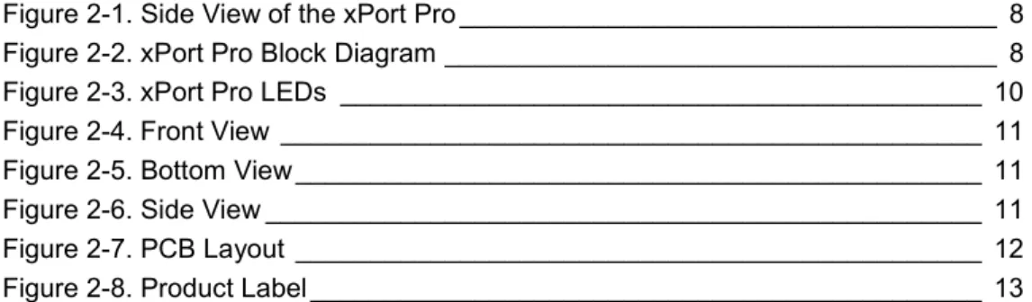
Figure 2-1. Side View of the xPort Pro ____________________________________ 8 Figure 2-2. xPort Pro Block Diagram _____________________________________ 8 Figure 2-3. xPort Pro LEDs ___________________________________________ 10 Figure 2-4. Front View _______________________________________________ 11 Figure 2-5. Bottom View ______________________________________________ 11 Figure 2-6. Side View ________________________________________________ 11 Figure 2-7. PCB Layout ______________________________________________ 12 Figure 2-8. Product Label _____________________________________________ 13
List of Tables
Table 2-1 xPort Pro Part Numbers ______________________________________ 7 Table 2-2 PCB Interface Signals ________________________________________ 9 Table 2-3 Ethernet Interface Signals (Industry Standards) ___________________ 10 Table 2-4 Absolute Maximum Ratings __________________________________ 13 Table 2-5 Recommended Operating Conditions ___________________________ 13 Table 2-6 Technical Specifications _____________________________________ 14
1. Introduction
About the Integration Guide
This guide provides the information needed to integrate the Lantronix xPort® Pro embedded device server into a customer printed circuit board. This manual is intended for engineers responsible for integrating the xPort Pro into their product. Note: This document covers xPort Pro Embedded Device Server versions XPP1004000-02R, XPP1002000-01R, XPP100200S-01R, XPP1002000-02R, XPP100200S-02R, XPP1003000-01R, XPP100300S-01R, XPP1003000-02R and XPP100300S-02R.
Additional Documentation
Visit the Lantronix web site at www.lantronix.com/support/documentation for the latest documentation and the following additional documentation.
Document Description
xPort Pro Embedded
Device Server User Guide Provides information needed to configure, use, and update the xPort Pro firmware.
xPort Pro Lx6 Embedded
Device Server User Guide Provides information needed to configure, use, and update the xPort Pro Lx6 firmware.
xPort Embedded Device Server Universal Demo Board Quick Start
Provides the steps for getting the xPort Pro up and running.
xPort Embedded Device Server Universal Demo Board User Guide
Provides information needed to use the xPort Pro on the demo board.
DeviceInstaller User
Guide Provides instructions for using the Windows-based utility to configure the xPort Pro and other Lantronix device servers.
Com Port Redirector User
2. Description and Specifications
The xPort Pro embedded device server is Lantronix’s most powerful, self-contained embedded networking module. Footprint compatible with the popular xPort product and running either Linux or the Lantronix Evolution OS® operating systems, the xPort Pro eliminates the complexity of designing network connectivity into a product and allows you to deploy advanced applications on the edge device itself. The thumb-sized xPort Pro provides everything you need in a single embedded solution. It effortlessly handles demanding applications with the power of a high-speed, advanced architecture 32-bit processor. The ample built-in memory allows virtually unlimited flexibility for customization and application enablement.
xPort Pro provides bullet-proof security by offering a variety of robust data encryption and authentication options. What’s more, the option to run Linux, with IPv6 built in, enables you to deploy custom applications and take advantage of the large feature libraries available for Linux developers. Critical agency certification has already been completed by Lantronix, reducing your test time and speeding time-to-market.
The xPort Pro Features
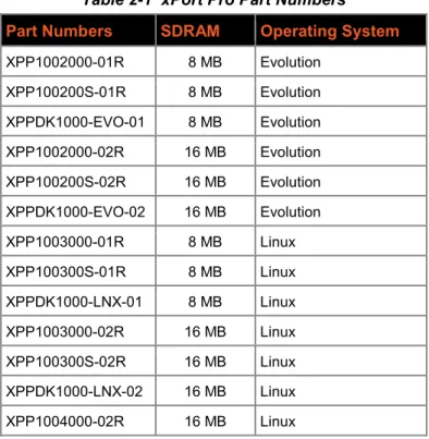
The xPort Pro contains a 32-bit Freescale® processor, with 8/16 megabytes (MB) of SDRAM (see Table 2-1), 16 MB of Flash and an integrated Broadcom® 10/100 PHY.
Table 2-1 xPort Pro Part Numbers
Part Numbers SDRAM Operating System
XPP1002000-01R 8 MB Evolution XPP100200S-01R 8 MB Evolution XPPDK1000-EVO-01 8 MB Evolution XPP1002000-02R 16 MB Evolution XPP100200S-02R 16 MB Evolution XPPDK1000-EVO-02 16 MB Evolution XPP1003000-01R 8 MB Linux XPP100300S-01R 8 MB Linux XPPDK1000-LNX-01 8 MB Linux XPP1003000-02R 16 MB Linux XPP100300S-02R 16 MB Linux XPPDK1000-LNX-02 16 MB Linux XPP1004000-02R 16 MB Linux
2: Description and Specifications The xPort Pro also contains the following:
3.3-volt serial interface All I/O pins are 3.3V tolerant Ethernet magnetics
Power supply filters Reset circuit +1.5V regulator
Crystals and Ethernet LEDs
The xPort Pro requires +3.3-volt power and is designed to operate in an extended temperature range (see technical data).
Figure 2-1. Side View of the xPort Pro
xPort Pro Block Diagram
The following drawing is a block diagram of the xPort Pro showing the relationships of the components.
Figure 2-2. xPort Pro Block Diagram
RJ45 CMOS IO RESET +3.3VDC
32-bit CPU FLASH/SDRAM
MAGNETICS LEDs
Rx Tx
2: Description and Specifications
PCB Interface
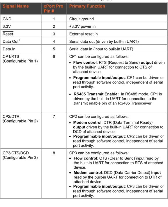
The xPort Pro has a serial port compatible with data rates up to 921600 bps. The serial signals (pins 4–8) are 3.3V CMOS logic level. The serial interface pins include +3.3V, ground, and reset. The serial signals connect to an internal UART driven at 3.3V. For applications requiring an external cable running with RS-232 or RS422/485 voltage levels, the xPort Pro must interface to a serial transceiver chip. We supply an RS-232 transceiver on the xPort Universal Demo Board for this purpose.
Note: The standard baud rate of 460800 bps is not supported.
Table 2-2 PCB Interface Signals
Signal Name xPort Pro
Pin # Primary Function
GND 1 Circuit ground
3.3V 2 +3.3V power in
Reset 3 External reset in
Data Out1 4 Serial data out (driven by built-in UART) Data In 5 Serial data in (input to built-in UART) CP1/RTS
(Configurable Pin 1) 6 CP1 can be configured as follows: • Flow control: RTS (Request to Send) output driven by the built-in UART for connection to CTS of attached device.
• Programmable input/output: CP1 can be driven or
read through software control, independent of serial port activity.
• RS485 Transmit Enable: In RS485 mode, CP1 is
driven by the built-in UART for connection to the transmit enable pin of an RS485 Transceiver. CP2/DTR
(Configurable Pin 2) 7 CP2 can be configured as follows: • Modem control: DTR (Data Terminal Ready) output driven by the built-in UART for connection to DCD of attached device.
• Programmable input/output: CP2 can be driven or
read through software control, independent of serial port activity.
CP3/CTS/DCD
(Configurable Pin 3) 8 CP3 can be configured as follows: • Flow control: CTS (Clear to Send) input read by the built-in UART for connection to RTS of attached device.
• Modem control: DCD (Data Carrier Detect) input read by the built-in UART for connection to DTR of attached device.
• Programmable input/output: CP3 can be driven or
read through software control, independent of serial port activity.
2: Description and Specifications
Ethernet Interface
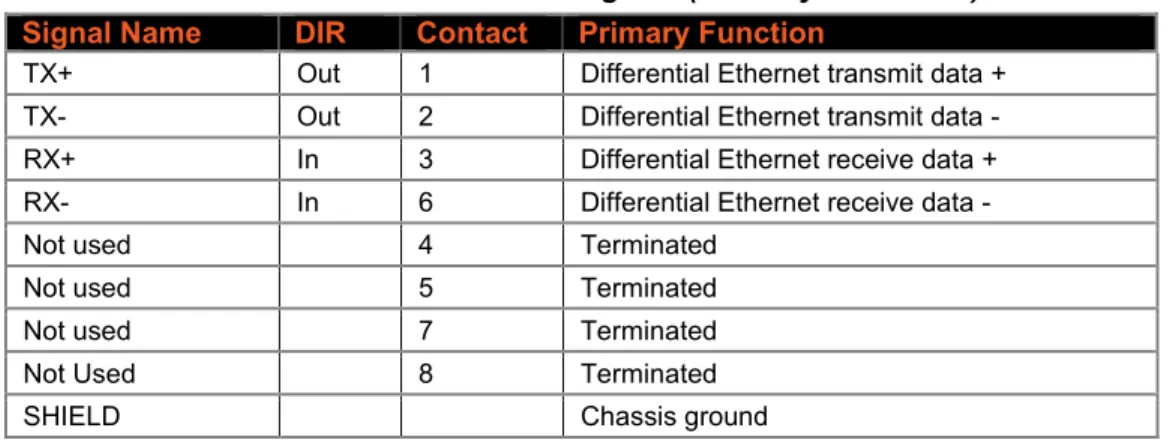
The Ethernet interface magnetics, RJ45 connector, and Ethernet status LEDs are all in the device server shell. The xPort Pro PHY is Auto MDIX capable allowing connection to either straight through or cross over Ethernet cables.
Table 2-3 Ethernet Interface Signals (Industry Standards)
Signal Name DIR Contact Primary Function
TX+ Out 1 Differential Ethernet transmit data + TX- Out 2 Differential Ethernet transmit data - RX+ In 3 Differential Ethernet receive data + RX- In 6 Differential Ethernet receive data -
Not used 4 Terminated
Not used 5 Terminated
Not used 7 Terminated
Not Used 8 Terminated
SHIELD Chassis ground
LEDs
The xPort Pro contains the following LEDs: Link (solid green, left LED)
Activity (blinking amber, right LED)
2: Description and Specifications
Dimensions
The xPort Pro dimensions are shown in the following drawings. Figure 2-4. Front View
Figure 2-5. Bottom View
Figure 2-6. Side View RIGHT LED 18.25 [0.719] 16.25 [0.640] 11.55 [0.455] 7.15 [0.281] CONTACT 1 CONTACT 8 5.85 [0.230]
14.50 [0.571] 4.03 [0.158]
13.50 [0.531] 1.85 [0.073] 3.25 [0.128] 3.30 [0.130] 1.27 [0.050] 0.40 [0.016] FRONT VIEW
DIMS = mm (in)
LEFT LED SHIELD TAB SHIELD TAB TOLERANCE .XX+/-0.20[0.008] 33.90 [1.335] 1.00 [0.039] 0.35 [0.014] 10.84 [0.427] 6.35 [0.250] 2.54 [0.100] 3.20 [0.126]
0.60 [0.024]
FRONT SHIELD
GROUND INTERFACE PINS
DIMS = mm (in) 11.90 [0.468] SHIELD TAB TOLERANCE .XX+/-0.20[0.008] 8 2 7 1
2: Description and Specifications
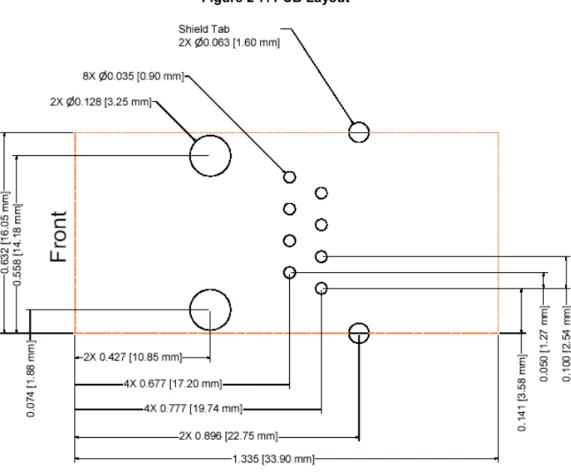
Recommended PCB Layout
The hole pattern and mounting dimensions for the xPort Pro device server are shown in the following drawing. For proper heat dissipation, it is recommended that the PCB have approximately 1 square inch of copper attached to the shield tabs. The shield tabs are an important source of heat sinking for the device.
The xPort Pro shield is considered “chassis ground” and should be separate from “signal ground”. ESD near the xPort Pro at the panel opening will likely jump to the shield.
We recommend using high voltage (~200V), low ESR, 0.01uF capacitors to connect chassis ground to both signal ground and 3.3V. This will cause any voltage spike from ESD to be imparted equally to both signal ground and 3.3V with no net voltage increase between 3.3V and signal ground. For the highest level of ESD protection of the xPort Pro, it is recommended that the shield not be directly connected to signal GND. The metal shield fingers around the xPort Pro’s RJ45 should physically contact the product housing when the housing is metal, or metallic coated.
The shield is also a heat sink for the internal 32-bit Processor. As in all heat sinking applications, the more copper connected to the heat sink the better. Adding 1 inch square inch of copper flood on the PCB is adequate to allow the xPort Pro to work up to +85°C. If the application does not expect to see temperatures up to +85°C the heat sink may be smaller than 1 square inch.
2: Description and Specifications
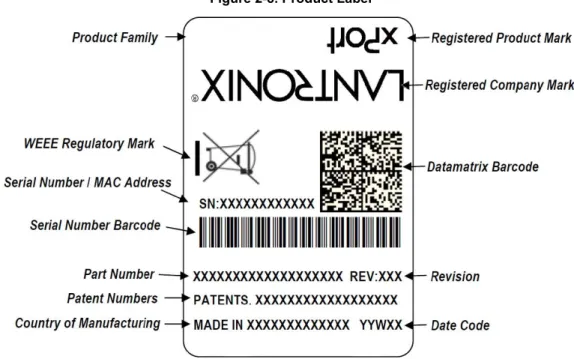
Product Information Label
The product information label contains important information about your specific unit, such as its product ID (name), bar code, part number, and Ethernet (MAC) address.
Figure 2-8. Product Label
Electrical Specifications
Caution: Stressing the device above the rating listed in this table may cause permanent damage to the xPort Pro. Exposure to Absolute Maximum Rating conditions for extended periods may affect the xPort Pro’s reliability.
Table 2-4 Absolute Maximum Ratings
Parameter Symbol Min Max Units
Supply Voltage VCC 0 3.6 Vdc
CPx, Reset, Data In, Data Out Voltage VCP -0.3 VCC +0.05 Vdc
Operating Temperature -40 85 oC
Storage Temperature -40 85 oC
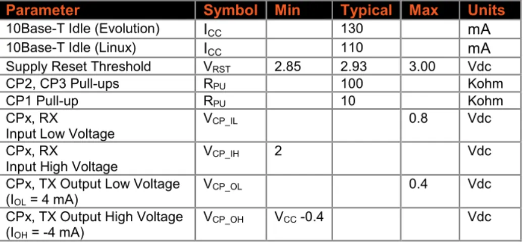
Table 2-5 Recommended Operating Conditions
Parameter Symbol Min Typical Max Units
Supply Voltage VCC 3.15 3.3 3.46 Vdc
Supply Voltage Ripples VCC_PP 2 %
100Base-TX Active
(Evolution) ICC 225 270 mA
100Base-TX Active (Linux) ICC 200 270 mA
100Base-TX Idle (Evolution) ICC 215 mA
100Base-TX Idle (Linux) ICC 175 mA
10Base-T Active (Evolution) ICC 145 250 mA
2: Description and Specifications
Parameter Symbol Min Typical Max Units
10Base-T Idle (Evolution) ICC 130 mA
10Base-T Idle (Linux) ICC 110 mA
Supply Reset Threshold VRST 2.85 2.93 3.00 Vdc
CP2, CP3 Pull-ups RPU 100 Kohm
CP1 Pull-up RPU 10 Kohm
CPx, RX
Input Low Voltage VCP_IL 0.8 Vdc
CPx, RX
Input High Voltage VCP_IH 2 Vdc
CPx, TX Output Low Voltage (IOL = 4 mA)
VCP_OL 0.4 Vdc
CPx, TX Output High Voltage (IOH = -4 mA)
VCP_OH VCC -0.4 Vdc
Note: All pins are not 5V tolerant.
Functional Specifications
Table 2-6 Technical Specifications
Category Description
CPU, Memory Freescale 32-bit Coldfire, 8/16 MB SDRAM (see Table 2-1), 16 MB flash, Firmware Upgradeable via TFTP, FTP, and serial port
Reset Circuit Internal 140ms minimum power-up reset pulse. Power-drop reset triggered at 2.95V. External reset input causes an internal 140ms minimum reset. Serial Interface CMOS (Asynchronous) 3.3V-level signals
Rate is software selectable and customizable: 300 bps to 921600 bps
Note:The standard baud rate of 460800 bps is not supported.
Serial Line Formats Data bits: 7 or 8 Stop bits: 1 or 2 Parity: odd, even, none Modem Control DTR, DCD
Flow Control XON/XOFF (software), CTS/RTS (hardware), None Programmable I/O 3 PIO pins (software selectable), sink or source 4mA max. Network Interface RJ45 Ethernet 10Base-T or 100Base-TX (auto-sensing) Compatibility Ethernet: Version 802.3u
Protocols Supported ARP, UDP/IP, TCP/IP, Telnet, ICMP, SNMP, DHCP, BOOTP, TFTP, FTP, Auto IP, SMTP, HTTPS, and HTTP
LEDs 10Base-T and 100Base-TX Link Activity Management Internal web server, SNMP (read only)
Serial login, Telnet login, DeviceInstaller utility, SSH
Security Password protection, locking features, optional Rijndael 256-bit encryption Internal Web Server Serves static web pages and Java applets
Storage capacity: 1MB Weight 0.34 oz (9.6 grams)
2: Description and Specifications
Category Description
software and Windows®-based Com Port Redirector Compliance Regulatory Approvals
FCC Part 15, Subpart B, Class B ICES-003 Issue 4 (2004), Class B
EN55022:2006 and EN55024:1998 + A1:2001 + A2:2003 AS/NZS CISPR22:2006
VCCI V-3/2009.04
EN61000-3-2:2006, EN 61000-3-3:1995+A1:2001+A2:2005 EN61000-4-2 (+/-4kV Contact Discharge, +/-8kV Air Discharge)
EN61000-4-3 (3 V/m (Unmodulated R.M.S.), 80 MHz - 1 GHz, 80% AM (1 kHz)) EN61000-4-4 (Ethernet Port: ±0.5 kV (Peak), 5 kHz)
EN61000-4-6 (Signal Port(s):3 V (Unmodulated R.M.S), 0.15 MHz - 80 MHz, 80% AM (1 kHz)
A:
xPort Pro 485 Connection Diagram
The following example illustrates a connection between the xPort Pro embedded device server and an external transceiver IC:
B:
Compliance Information
(According to ISO/IEC Guide 22 and EN 45014)
Manufacturer’s Name & Contact Information:
Lantronix, Inc.7535 Irvine Center Drive Suite 100
Irvine, CA 92618, USA Toll Free: 800-526-8766 Phone: 949-453-3990 Fax: 949-453-3995
Declares that the following product:
Product Name Models:
xPort® Pro Embedded Device Server
xPort® Pro Lx6 Embedded Device Server
Conforms to the following standards or other normative documents:
Electromagnetic Emissions/Immunity:
FCC Part 15, Subpart B, Class B ICES-003 Issue 4 (2004), Class B
EN55022:2006 and EN55024:1998 + A1:2001 + A2:2003 AS/NZS CISPR22:2006
VCCI V-3/2009.04
EN61000-3-2:2006, EN 61000-3-3:1995+A1:2001+A2:2005 EN61000-4-2 (+/-4kV Contact Discharge, +/-8kV Air Discharge)
EN61000-4-3 (3 V/m (Unmodulated R.M.S.), 80 MHz - 1 GHz, 80% AM (1 kHz)) EN61000-4-4 (Ethernet Port: ±0.5 kV (Peak), 5 kHz)
EN61000-4-6 (Signal Port(s):3 V (Unmodulated R.M.S), 0.15 MHz - 80 MHz, 80% AM (1 kHz)
EN61000-4-8 (50 Hz, 1.0 A/m (R.M.S.)
RoHS, REACH and WEEE Compliance Statement
Please visit http://www.lantronix.com/legal/rohs/ for Lantronix’s statement about RoHS, REACH and WEEE compliance.