M&C Software
for Windows™
Windows-Based Monitor and Control Software for
Comtech EF Data Satellite Terminals
M&C Software
for Windows
™
Table of Contents
TABLE OF CONTENTS ... III
PREFACE ... XIII
About this Manual ... xiii
Reporting Comments or Suggestions Concerning this Manual... xiii
Conventions and References ... xiii
Metric Conversion ... xiii
Recommended Standard Designations ... xiii
Trademarks ... xiii
Cautions and Warnings ... xiv
Disclaimer ... xiv
Customer Support ... xv
Online Customer Support ...xv
CHAPTER 1. GETTING STARTED ... 1–1
1.1 System Requirements ... 1–1
1.2 Installation ... 1–2
1.3 Screen Descriptions ... 1–2
1.4 Use of Colors ... 1–4
1.5 Navigation ... 1–5
M&C Software for Windows Revision 4
Table of Contents MN/M-CWIN.IOM
2.3 The Menu Bar ... 2–7
2.3.1 File Menu ... 2–7
2.3.2 Edit Menu ... 2–7
2.3.3 Options Menu ... 2–8
2.3.4 Help Menu ... 2–8
2.4 Screen Details ... 2–9
2.4.1 Status Screen ... 2–10
2.4.2 Pre-Select Screen ... 2–11
2.4.3 Comm/Util Screen ... 2–13
2.4.4 Terminal Screen ... 2–15
2.4.5 Fault Log Screen ... 2–17
CHAPTER 3. TROUBLESHOOTING ... 3–1
3.1 EIA-232 to EIA-485 Converters ... 3–1
3.2 Verifying Physical Connections ... 3–2
3.3 Communication with Redundant Systems ... 3–3
3.4 Addressing ... 3–4
Figures
Figure 2-1. M&C Non-support Warning Dialog Box ... 2–1 Figure 2-2. Communications Dialog Box ... 2–3 Figure 2-3. Command Delay Dialog Box ... 2–4 Figure 2-4. Configuration Dialog Box ... 2–5 Figure 2-5. Terminal Macros Dialog Box ... 2–6 Figure 2-6. File Menu ... 2–7 Figure 2-7. Edit Menu ... 2–7 Figure 2-8. Options Menu ... 2–8 Figure 2-9. Help Menu ... 2–8 Figure 2-10. Status Screen ... 2–10 Figure 2-11. Pre-Select Screen ... 2–12 Figure 2-12. Comm/Util Screen ... 2–13 Figure 2-13. Acquire Communications Dialog Box ... 2–14 Figure 2-14. Terminal Screen ... 2–15 Figure 2-15. Fault Log Screen ... 2–17 Figure 3-1. Non-KST-2000A/B Redundant System Hierarchy ... 3–3 Figure 3-2. KST-2000A/B Redundant Systems Hierarchy ... 3–4
PREFACE
About this Manual
This manual describes the Comtech EF Data WindowsTM based Monitor and Control (M&C) software used with Comtech EF Data C-band and Ku-band terminal systems. This is a technical document intended for earth station engineers, technicians, and operators responsible for the operation and maintenance of Comtech EF Data terminal systems.
Reporting Comments or Suggestions Concerning this Manual
Comments and suggestions regarding the content and design of this manual will be appreciated. To submit comments, please contact the Comtech EF Data Technical Publications Department:
Conventions and References
Metric Conversion
Metric conversion information is located on the inside back cover of this manual. This information is provided to assist the operator in cross-referencing non-Metric to Metric conversions.
M&C Software for Windows Revision 4
Preface MN/M-CWIN.IOM
Cautions and Warnings
IMPORTANT
IMPORTANT or NOTE indicates a statement associated with the task being
performed or information critical for proper equipment function.
CAUTION
CAUTION indicates a hazardous situation that, if not avoided, may result in
minor or moderate injury. CAUTION may also be used to indicate other unsafe practices or risks of property damage.
WARNING
WARNING indicates a potentially hazardous situation that, if not avoided, could
result in death or serious injury.
Disclaimer
Comtech EF Data has reviewed this manual thoroughly in order that it will be an easy-to-use guide to your equipment. All statements, technical information, and recommendations in this manual and in any guides or related documents are believed reliable, but the accuracy and completeness thereof are not guaranteed or warranted, and they are not intended to be, nor should they be understood to be, representations or warranties concerning the products described. Further, Comtech EF Data reserves the right to make changes in the specifications of the products described in this manual at any time without notice and without obligation to notify any person of such changes.
If you have any questions regarding your equipment or the information in this manual, please contact the Comtech EF Data Customer Support Department.
M&C Software for Windows Revision 4
Preface MN/M-CWIN.IOM
Customer Support
Contact the Comtech EF Data Customer Support Department for:
• Product support or training
• Reporting comments or suggestions concerning manuals
• Information on upgrading or returning a product A Customer Support representative may be reached at:
Comtech EF Data
Attention: Customer Support Department 2114 West 7th Street
Tempe, Arizona 85281 USA
480.333.2200 (Main Comtech EF Data number) 480.333.4357 (Customer Support Desk)
480.333.2161 FAX
To return a Comtech EF Data product (in-warranty and out-of-warranty) for repair or replacement:
• Contact the Comtech EF Data Customer Support Department. Be prepared to supply the Customer Support representative with the model number, serial number, and a description of the problem.
• Request a Return Material Authorization (RMA) number from the Comtech EF Data Customer Support representative.
• Pack the product in its original shipping carton/packaging to ensure that the product is not damaged during shipping.
• Shipthe product back to Comtech EF Data. (Shipping charges should be prepaid.)
Online Customer Support
An RMA number request can be requested electronically by contacting the Customer Support
Department through the online support page at
M&C Software for Windows Revision 4
Preface MN/M-CWIN.IOM
Chapter 1. GETTING STARTED
The Comtech EF Data Monitor and Control (M&C) software is a Windows-based program designed to provide a user-friendly interface for the control and monitoring of Comtech EF Data’s C-Band and Ku-Band satellite terminals. Specifically, the M&C software provides simplified user control, automatic system monitoring, and fault logging for terminal system components.
This software operates with single or redundant RF terminal systems. Refer to Chapter 2
for operation information.
1.1
System Requirements
The M&C software requires the following:
• PC with Windows OS (such as Windows NT or Windows XP)
• One available COM port
Monitor and Control Software for Windows Revision 4
Getting Started MN/M-CWIN.IOM
1.2
Installation
IMPORTANT
1. Delete any existing M&C application from the computer before installing this version. If this deletion is not performed, the installation process may appear to copy the M&C application files onto the computer without actually doing
so. Then, when the application is next launched, the old M&C application will
be used instead of the newer version.
2. Download and unzip the file archive from
(Support/Software Downloads/Utilities & Demo Software) or insert installation disk into appropriate disk drive on your PC.
3. Double-click the setup.exe file to initiate the installation application, which copies the appropriate files to the hard drive.
4. Follow the instructions on the screen to complete the installation process.
1.3 Screen
Descriptions
The application uses five primary screens. Each screen performs a unique function and is described below.
Screen Description
Status Screen The Status Screen is the primary tool for monitoring the operating configuration,
maintenance data, and fault status of the equipment. The number of panels displayed on this screen varies from one to three, depending upon the application configuration and product type as set by the configuration dialog box.
The information provided by this screen is refreshed at a periodic rate. This refresh rate depends upon the operating system, baud rate setting, and the application configuration. The actual refresh rate is displayed on the Terminal Screen and may change as background responsibilities change.
Monitor and Control Software for Windows Revision 4
Getting Started MN/M-CWIN.IOM
Screen Description
Pre-Select Screen The Pre-Select Screen provides the status of the current configuration information (up and down converter frequencies and attenuations) for each of the three customer-programmable pre-selects stored within the RF terminal.
The number of panels displayed on this screen varies from one to two depending upon the configuration setting from the configuration dialog box.
The information provided by this screen is refreshed at a periodic rate. This refresh rate is dependent upon the operating system, baud rate setting, and the application configuration. The actual refresh rate is displayed on the Terminal Screen and may change as background responsibilities change.
Comm/Util Screen The Comm/Util Screen is divided into two sections:
• The top half of each panel is the communication setup section. This section displays presently configured communication parameters of address, baud rate, and parity. The “Acquire Communications” button is provided as an easy way to poll
combinations of address, baud rate, and parity to find any RF terminals connected to the assigned COM port.
• The bottom half of each panel provides an interface for some of the more commonly used utility features of the RF terminals.
The number of panels displayed on this screen varies from one to three depending upon the configuration setting from the configuration dialog box.
The information provided by this screen is refreshed at a periodic rate. This refresh rate is dependent upon the operating system, baud rate setting, and the application configuration. The actual refresh rate is displayed on the Terminal Screen and may change as background responsibilities change.
Terminal Screen This screen allows the user to type ASCII characters representing valid Comtech EF Data remote commands to be transmitted to all connected terminals. This screen is typically used to enter remote commands not covered by the other four screens.
Convenient macro keys are available on this screen to provide an easy way of sending remote commands to connected RF terminals. The remote commands entered on this screen are transmitted as soon as the present background command has been processed. Background communications occur during periods of no activity (with respect to the user), thus allowing the other four screens to always show the latest data reported by the RF terminals.
Monitor and Control Software for Windows Revision 4
Getting Started MN/M-CWIN.IOM
Current Fault Log Screen
The RF terminals connected to this application do not contain real-time clocks, and therefore, cannot log time and date stamp information when the system faults. The application provides this fault logging feature using the operating system’s time and date. This information is written to the “RFMC.FLT” file when the application exits. Clearing these faults is possible through the EDIT menu.
This application polls the connected system(s) for present fault information. Certain products like the KST-2000 A/B/L, set faults as they occur, but also remove the faults as they clear. If the application refresh rate is larger than the time any present fault conditions persist, then the application may miss the logging of the faults. It is recommended to poll the connected system(s) for their stored faults when this situation arises. This situation will only occur for those products which have the capability of reporting stored faults. The information provided by this screen is refreshed at a periodic rate. This refresh rate is dependent upon the operating system, baud rate setting, and the application configuration. The actual refresh rate is displayed on the Terminal Screen and may change as background responsibilities change.
1.4
Use of Colors
The M&C application screen uses three colors to represent various states of the serial connection and remote command parameters transmitted to the RF terminals.
Color Description
Gray Used in two situations:
• If an entire panel is highlighted, communications are presently established with the corresponding RF terminal.
• If an individual text box is highlighted, the entered parameter was accepted by the RF terminal.
Yellow Appears after a mouse click from any MODIFY button, representing data which may be changed by the user. Values may be changed using either the keyboard or the spinner control displayed to the right of the text box highlighted in yellow.
Red Used in two ways:
• If an entire panel is highlighted, communication to the specific RF terminal has been lost.
• If an individual text box is highlighted, the entered parameter was rejected by the RF terminal.
Monitor and Control Software for Windows Revision 4
Getting Started MN/M-CWIN.IOM
1.5
Navigation
The active screen is displayed on the lower left corner of the screen. The assignment of the function keys remains consistent from screen to screen.
Key Assignment Key Function
[F2] Selects the Status screen.
[F3] Selects the Comm/Util screen.
[F4] Selects the Pre-Select screen.
[F5] Selects the Terminal screen.
[F6] Selects the Fault Log screen.
[F7] Clears all the stored faults within every RF terminal presently in communication with the application.
[F8] Clears all selected faults within the Fault Log screen. Only active when “Fault Log Screen” is active. [F9] Clears all faults from the Fault Log screen.
Only active when “Fault Log Screen” is active.
[↑] Scrolls the vertical scroll bar up or moves left one character position, depending upon present cursor location.
[↓] Scrolls the vertical scroll bar up or moves left one character position, depending upon present cursor location.
[→] Moves cursor one character right
[←] Moves cursor one character left.
[ESC] Defaults to the CANCEL button when pressed.
[ENTER] Chooses the button presently selected.
Monitor and Control Software for Windows Revision 4
Getting Started MN/M-CWIN.IOM
1.6
Equipment Line
Communications are continually verified with respect to the configuration and the products with which the application may be communicating. Each of the first three screens displays panels showing the data contained within each RF terminal.
• When communications are established to an RF terminal, that specific panel is highlighted in GRAY and the terminal’s version information is displayed.
• When communications are interrupted to an RF terminal, that specific panel is highlighted in RED and the terminal’s version information changes to read “NO COMMUNICATIONS”.
Chapter 2. OPERATION
This chapter provides information regarding the operation of the M&C software.
2.1
Supported Terminals
The initial release of this software supports the KST-2000(A/B/L).
In future revisions, the application will support the following Comtech EF Data RF terminals:
• RFT-500 (2.5 MHz, 125 kHz, and Multi-carrier)
• RFT-505
• RFT-700
• RFT-705
The M&C displays (N/A) in front of non-supported RFT terminals on the configuration dialog box. If a non-supported RFT is chosen for the active configuration the application responds with the following dialog box (Figure 2-1).
Monitor and Control Software for Windows Revision 4
Operation MN/M-CWIN.IOM
2.2
Startup
To start the application, double-click the M&C icon (shown below) with the left mouse button.
The application boots by briefly showing the Copyright and Information Screen, and proceeds to read the supporting initialization files (Table 2-1). Factory default values are used when the application is launched for the first time. Subsequently, these files contain the application’s last known configuration saved from the previous session.
Note: Due to the last configuration information being saved, the application icon is placed in the STARTUP folder to recover reliably from unexpected power losses.
Table 2-1. Support Initialization Files
File Name Definition
RFMC.INI This file contains all application configuration information, allowing consecutive executions to maintain the last known arrangement.
RFMC.KEY When macros are defined on the terminal macros dialog, they are saved in this file for later recollection when the application exits. If this file is not empty, the application loads the entire contents and displays the associated macro button on the Terminal Screen.
RFMC.FLT If this file is not empty, the application loads the entire contents and displays it on the Fault Log Screen allowing a method of tracking all faults just before power loss. The application then proceeds to retrieve all presently active faults from all devices and appends this information to the data previously read from the fault log file. The fault log screen will show date and time stamp information for all logs just before and after intermittent power losses.
2.2.1
Initial Setup
Factory default values are used when the application is launched for the first time. As soon as the application has finished initializing, use the Options menu to display the configuration and communications dialog boxes.
Monitor and Control Software for Windows Revision 4
Operation MN/M-CWIN.IOM
2.1.1.1
Communications Dialog Box
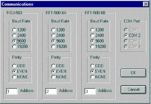
The communications dialog box allows settings of baud rate, parity, and address selection for each individual RF terminal or RSU-503 device.
The dialog box may appear differently, depending upon the configuration chosen on the configuration dialog box.
Example:
Single thread systems will only allow access to the center frame.
Figure 2-2 shows the dialog box as it appears for a redundant RFT-500 system using COM port 2 for communication.
Monitor and Control Software for Windows Revision 4
Operation MN/M-CWIN.IOM
2.1.1.2
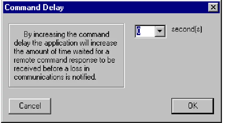
Command Delay Dialog Box
The application performs background tasks by submitting remote commands to connected hardware and updating the screen values with the responded data.
• When the application submits each command, it waits a default amount of time for the expected response.
• When no response is received, the panel associated with that specific RF terminal is highlighted RED, indicating a loss in communications.
• For most users, this default time delay will be satisfactory.
However, users may increase the command delay by entering a specified amount of time to lengthen the wait for a response.
Monitor and Control Software for Windows Revision 4
Operation MN/M-CWIN.IOM
2.1.1.3 Configuration Dialog Box
The configuration dialog box (Figure 2-4) allows choosing a specific Comtech EF Data RF terminal to tailor the application directly to that hardware. Additionally, the system may be configured for single thread or redundant operation.
Note: The KST-2000L is not configured for redundant operation.
Figure 2-4. Configuration Dialog Box
Monitor and Control Software for Windows Revision 4
Operation MN/M-CWIN.IOM
2.1.1.4
Terminal Macros Dialog Box
The third choice under the Options menu is the Terminal Macros dialog box (Figure 2-5). This dialog box is used to create twelve user-defined macros as one-click avenues on the Terminal Screen for “pipe-lining” ASCII characters to an RF terminal. The characters are sent in the form of Comtech EF Data-formatted remote commands.
The option of appending a 'cr' the end of a remote command is available as a check box located to the right of each text box. When OK is clicked, these user-defined macros appear on the lower right corner of the Terminal Screen.
Monitor and Control Software for Windows Revision 4
Operation MN/M-CWIN.IOM
2.3
The Menu Bar
The menu bar contains four different menus: File Menu, Edit Menu, Options Menu, and Help Menu.
2.3.1 File
Menu
The File menu (Figure 2-6) allows navigation to any of five different screens by choosing the appropriate menu option with the mouse, pressing the underlined key, or typing the associated function key on the key board.
Figure 2-6. File Menu
Note: The last choice exits the application and saves the present configuration information in all of the three supporting application files.
2.3.2 Edit
Menu
Monitor and Control Software for Windows Revision 4
Operation MN/M-CWIN.IOM
• The Clear Selected Faults is selectable only when the active screen is the Fault Log Screen. When selected, it deletes the user’s highlighted faults from M&C application memory and does not re-log those faults, unless the application is restarted or a change is made on the configuration dialog box. This is a convenient way to focus on important logs by erasing specific, less important ones.
• The Clear All Faults is only selectable when the active screen is the Fault Log Screen. When selected, it deletes all faults from M&C application memory and immediately re-logs all actively reported faults from all devices connected to the application. This an easy way to get a quick look at only the presently active faults.
2.3.3 Options
Menu
The Options menu (Figure 2-8) is described in section 2.1.1.1.
Figure 2-8. Options Menu
2.3.4 Help
Menu
The Help menu (Figure 2-9) provides access to the copyright and information screen.
Monitor and Control Software for Windows Revision 4
Operation MN/M-CWIN.IOM
2.4
Screen Details
The application uses five primary screens. Each screen reports or allows data changes to occur. The refresh rate of the program (the amount of time it takes to refresh every value in the application with newly reported results from all RF terminals) is dynamic and is shown on the Terminal Screen.
External processes (such as entering remote commands on the Terminal Screen, modifying values on the Status Screen, modifying values on the Comm/Util Screen, or reducing the baud rate, etc.), tend to increase the refresh rate. As the user reduces requests to the application, the refresh rate is also reduced. This effectively increases the number of times per second the application can query the RF terminals for updated information.
Note: When interfacing with terminals that are configured for Transmit-Only, screens and commands referring to down conversion or receive functions are not available.
Monitor and Control Software for Windows Revision 4
Operation MN/M-CWIN.IOM
2.4.1
Status Screen
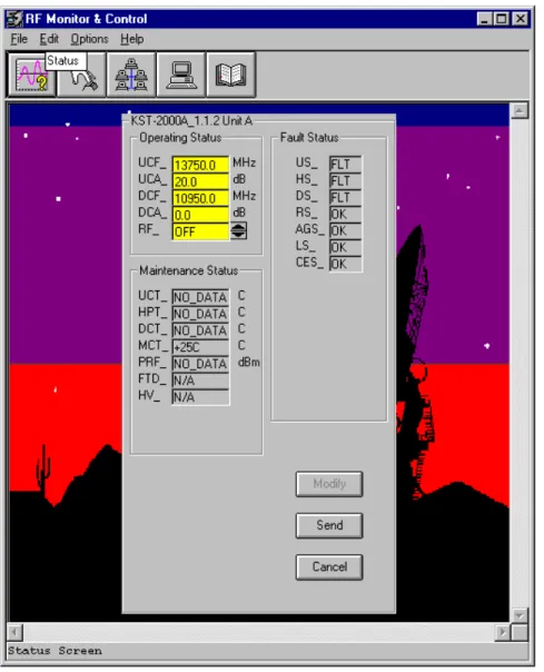
The Status Screen (Figure 2-10) reports faults, frequencies, attenuation values, and redundancy parameters. The screen takes on different forms depending upon the
configuration (see Section 2.1.1.3). Shown below is the screen for a single thread system supporting one KST-2000A unit.
Figure 2-10. Status Screen
Monitor and Control Software for Windows Revision 4
Operation MN/M-CWIN.IOM
CANCEL and SEND buttons, the highlighted yellow fields are changed back to gray, thus showing those fields may not be modified until the MODIFY button is clicked again.
2.4.2
Pre-Select Screen
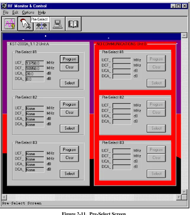
The Pre-Select Screen (Figure 2-11) reports user-selectable frequency and attenuation parameters. The screen's appearance differs based on how the configuration is chosen from the configuration dialog box. Figure 2-11 shows the screen for a redundant system supporting two Comtech EF Data KST-2000A units.
The application has not acquired communications with unit B, represented by showing the entire panel in red. Connection to unit A is fully functional. This screen shows the user-chosen pre-selected sets of frequency and attenuation that are most commonly used with unit A.
Pre-select #1 is programmed; however, it may or may not be the active settings of this unit. To see the unit's active settings, view the Status Screen. Pre-selects #2 and #3 are not programmed and may be programmed with active settings of frequency and attenuation by clicking the associated PROGRAM button.
The CLEAR button erases all values of frequency and attenuation as shown by pre-selects #2 and #3.
The SELECT button programs the associated pre-select values as active settings. Once the SELECT button is pressed, the Status Screen shows those exact values as active by the associated RF terminal.
Monitor and Control Software for Windows Revision 4
Operation MN/M-CWIN.IOM
Monitor and Control Software for Windows Revision 4
Operation MN/M-CWIN.IOM
2.4.3
Comm/Util Screen
The Comm/Util Screen (Figure 2-12) reports communication settings as set by the communications dialog box. Click the MODIFY button to allow changes to be made.
Monitor and Control Software for Windows Revision 4
Operation MN/M-CWIN.IOM
The ACQUIRE COMMUNICATIONS button loads the Acquire Communications dialog box (Figure 2-13) and proceeds to run through all combinations of address, baud, and parity to find a response from a lost-but-connected RF terminal.
Figure 2-13. Acquire Communications Dialog Box
The utility functions frame listed at the bottom half of each panel are different for each RF terminal. These values are allowed to be modified using the MODIFY, CANCEL, and SEND buttons described earlier in Section 2.3.1.
Monitor and Control Software for Windows Revision 4
Operation MN/M-CWIN.IOM
2.4.4
Terminal Screen
The terminal screen (Figure 2-14) allows keyboard characters to be typed in and transmitted to connected RF terminals.
Monitor and Control Software for Windows Revision 4
Operation MN/M-CWIN.IOM
The communication setup frame shows communication parameters as set in the
communications dialog box. Specifically, it shows values associated with the most likely recipient and depends only upon the application’s configuration. As listed below, certain configurations imply most likely recipients.
1. Redundant : non KST-2000A/B systems; communications refer to an RSU-503 unit.
2. Redundant : KST-2000A/B systems; communications refer to unit A. 3. All single thread systems; communications refer to unit A.
The terminal macros dialog box allows user-definable remote command shortcuts to be created and placed on the lower right corner of this screen. For further information see Section 2.2.1.
Monitor and Control Software for Windows Revision 4
Operation MN/M-CWIN.IOM
2.4.5
Fault Log Screen
The fault log screen (Figure 2-15) shows all active faults as reported by all RF terminals presently connected to the application. The user-selectable highlighted areas are useful for clearing selected faults from the application’s memory. For further fault clearing information, see Section 2.3.
The scroll bar allows access up to a maximum of 1000 stored faults as they are reported by the RF terminals.
Monitor and Control Software for Windows Revision 4
Operation MN/M-CWIN.IOM
Chapter 3. TROUBLESHOOTING
This chapter describes troubleshooting possible problems and methods for solving them.
3.1
EIA-232 to EIA-485 Converters
Note: The KST-2000L is not configured for redundant operation.
Since this application currently supports redundant KST-2000A/B configurations, multi-drop EIA-485 is the only method of simultaneously communicating to both devices in the redundant configuration.
The EIA-232 COM port on the back of a PC must be converted to the EIA-485 hardware protocol for reliable communication to take place.
Monitor and Control Software for Windows Revision 4
Troubleshooting MN/M-CWIN.IOM
CAUTION
Some EIA-232 to EIA-485 converters electrically connect the RTS (Request to Send) signal to the EIA-485 line drivers. This creates a half-duplex communication path that allows either the transmit or receive line drivers to operate individually, but never simultaneously (see the following
illustration). EIA-485 EIA-232 RTS o o o TX-B TX-A RX-A RX-B RX TX
The application does not have the ability to change the logic state of the RTS control line from the EIA-232 side of the interface. When the COM port is initialized, RTS is at logic one and remains at that level for all transmissions and receptions of serial data through that COM port. Therefore, the
illustrated converters will not work with this application.
3.2
Verifying Physical Connections
Before the application can be used to help solve communication link problems, it is imperative that all physical connections are verified between the host PC and the object RF terminal or RSU-503 unit. It is also important that the communications dialog box is set to the available COM port.
As a last resort, try the Acquire Communications feature on the Comm/Util Screen to allow the application to search for a device. See Section 2.2.3 for further information on this feature.
Note: Refer to the respective remote control specification for details regarding the RSU, RFT, or KST inter-connection.
Monitor and Control Software for Windows Revision 4
Troubleshooting MN/M-CWIN.IOM
3.3
Communication with Redundant Systems
All non-KST-2000A/B redundant systems serviced by the application use a branch approach in their system communications: i.e., the user communicates to the system through a single point (the redundant controller); the single point then provides communication branching to the remaining equipment (the two RFTs).
This architecture mandates that the application must first be able to communicate to the redundant controller before it can provide the desired M&C functions for the two RFTs. Therefore, when dealing with this type of redundant system and a communication link error is evident, focus on the link between the PC and the RSU-503 first.
An example of this type of system is outlined in Figure 3-1.
Laptop computer RSU-503
RFT-xxx RFT-xxx
Figure 3-1. Non-KST-2000A/B Redundant System Hierarchy
Monitor and Control Software for Windows Revision 4
Troubleshooting MN/M-CWIN.IOM
All KST-2000A/B redundant systems serviced by the application also use a branch approach in their system hierarchy; however, the PC (not the RSU-503) does the branching. The COM port must be converted into multi-drop EIA-485 as is shown in Figure 3-2.
Laptop computer
KST-2000A/B KST-2000A/B
Figure 3-2. KST-2000A/B Redundant Systems Hierarchy
3.4
Addressing
The following are the factory default settings of device addressing.
Table 3-1. Non-KST-2000A/B Redundant Systems
Product Address
RSU-503 1
RFT Unit A 2
RFT Unit B 3
Table 3-2. KST-2000A/B Redundant Systems
Product Address
KST-2000A/B Unit A 2
METRIC CONVERSIONS Units of Length
Unit Centimeter Inch Foot Yard Mile Meter Kilometer Millimeter
1 centimeter — 0.3937 0.03281 0.01094 6.214 x 10⁻⁶ 0.01 — —
1 inch 2.540 — 0.08333 0.2778 1.578 x 10⁻⁵ 0.254 — 25.4
1 foot 30.480 12.0 — 0.3333 1.893 x 10⁻⁴ 0.3048 — —
1 yard 91.44 36.0 3.0 — 5.679 x 10⁻⁴ 0.9144 — —
1 meter 100.0 39.37 3.281 1.094 6.214 x 10⁻⁴ — — —
1 mile 1.609 x 10⁵ 6.336 x 10⁴ 5.280 x 10³ 1.760 x 10³ — 1.609 x 10³ 1.609 —
1 mm — 0.03937 — — — — — —
1 kilometer — — — — 0.621 — — —
Temperature Conversions
Units of Weight
Ounce Ounce Pound Pound
Unit ° Fahrenheit ° Centigrade
32° Fahrenheit —
0 (water freezes)
212° Fahrenheit —
100 (water boils)
-459.6° Fahrenheit —
273.1 (absolute 0)
Formulas
C = (F - 32) * 0.555