ECE35
Homework #1 (Spring 2017, Taur)
All homework problems come from the textbook, “Introduction to Electric Circuits”, by Svoboda & Dorf, 9th Edition.
P 1.2-3 The current in a circuit element is i(t) = 4 sin 5t A when t ≥ 0 and i(t) = 0 when t < 0. Determine the total charge that has entered a circuit element for t ≥ 0.
Hint: (0) ( ) 0 0 0
t
q i d d
Solution:
0
0 4 0 4 40 4sin 5 0 cos 3 cos 3 C
5 5 5
t t t
q t
i d q
d tP 1.5-7 Find the power, p(t), supplied by the element shown in Figure P 1.5-6 when v(t) = 8 sin 3t V and i(t) = 2 sin 3t A.
Hint: (sin )(sin ) 1(cos( ) cos( ) ) 2
at bt a b t ab t
Answer: p(t) = 8 – 8cos 6t W
Figure P 1.5-7 Solution:
8sin 3
2sin 3
8 cos 0 cos 6
8 8cos 6 Wp t v t i t t t t t
Here is a MATLAB program to plot p(t):
Clear
t0=0; % initial time
tf=2; % final time
dt=0.02; % time increment
t=t0:dt:tf; % time
v=8*sin(3*t); % device voltage
for k=1:length(t)
p(k)=v(k)*i(k); % power
end
plot(t,p)
xlabel('time, s');
P 1.7-2 Conservation of energy requires that the sum of the power absorbed by all of the elements in a circuit be zero. Figure P 1.7-2 shows a circuit. All of the element voltages and currents are specified. Are these voltage and currents correct? Justify your answer.
Hint: Calculate the power absorbed by each element. Add up all of these powers. If the sum is zero, conservation of energy is satisfied and the voltages and currents are probably correct. If the sum is not zero, the element voltages and currents cannot be correct.
Figure P 1.7-2
Solution:
Notice that the element voltage and current of some branches do not adhere to the passive convention. The sum of the powers absorbed by each branch are:
-(3 V)(3 A)+(3 V)(2 A)+ (3 V)(2 A)+(4 V)(3 A)+(-3 V)(-3 A)+(4 V)(-3 A)
= -9 W + 6 W + 6 W + 12 W + 9 W -12 W
0 W
P 2.2-3 A linear element has voltage v and current i as shown in Figure P 2.2-3a. Values of the current i and
corresponding voltage v have been tabulated as shown in
Figure P 2.2-3b. Represent the element by an equation
that expresses v as a function of i. This equation is a
model of the element. (a) Verify that the model is linear.
(b) Use the model to predict the value of v
corresponding to a current of i = 6 mA. (c) Use the
model to predict the value of i corresponding to a
voltage of v = 12 V.
Figure P 2.2-3
Hint: Plot the data. We expect the data points to lie on a straight line. Obtain a linear model of the element by representing that straight line by an equation.
Solution:
(a) The data points do indeed lie on a straight line. The slope of the line is 256.5 V/A and the line passes through the origin so the equation of the line is v256.5i. The element is indeed linear.
(b) When i = 6 mA, v = (256.5 V/A)(6 mA) = (256.5 V/A)(0.006 A) = 1.054 V
(c) When v = 12 V, 12 0.04678
256.5
P 2.4-10 The voltage source shown in Figure P 2.4-10 is an adjustable dc voltage source. In other words, the voltage vs is a constant voltage, but the value of that constant can be adjusted. The tabulated data were collected as follows. The voltage, vs, was set to some value, and the voltages across the resistor, va and vb, were measured and recorded. Next, the value of vs was changed,
Figure P 2.4-10
and the voltages across the resistors were measured again and recorded. This procedure was repeated several times. (The values of vs were not recorded.) Determine the value of the resistance, R.
Solution:
Label the current i as shown. That current is the element current in both resistors. First
a
40 v i
Next b a b
a
40 40
v v
v R i R R
v
For example,
7.05
40 24
11.75
P 2.5-1 A current source and a voltage source are connected in parallel with a resistor as shown in Figure P 2.5-1. All of the elements connected in parallel have the same voltage, vs in this circuit. Suppose that vs = 15 V, is = 3 A, and R = 5 Ω. (a) Calculate the current i in the resistor and the power absorbed by the resistor. (b) Change the current source current to is = 5 A and recalculate the current, i, in the resistor and the power absorbed by the resistor.
Answer: i = 3 A and the resistor absorbs 45 W both when is = 3 A and when is = 5 A.
Figure P 2.5-1
Solution:
(a) 15 2
23 A and 5 3 45 W 5
s v
i P R i
R
(b) i and do not depend on .P is
The values of and are 3 A and 45 W, both when i P is 3 A and when is 5 A.
P 2.5-2 A current source and a voltage source are connected in series with a resistor as shown in Figure P 2.5-2. All of the elements connected in series have the same current, is, in this circuit. Suppose that vs = 10 V, is = 3 A, and R = 5 Ω. (a) Calculate the voltage v across the resistor and the power absorbed by the resistor. (b) Change the voltage source voltage to vs = 5 V and recalculate the voltage, v, across the resistor and the power absorbed by the resistor.
Answer: v = 10 V and the resistor absorbs 20 W both when vs = 10 V and when vs = 5 V.
Figure P 2.5-2
Solution:
(a) From Ohm’s law vR is5 3
15 V. (The resistor voltage does not dependon the voltage source voltage.) Next
2 2
15
45 W 5
v P
R
.
(b) Since v and do not depend on P vs the values of v and P are 15 V and 45 W
s s
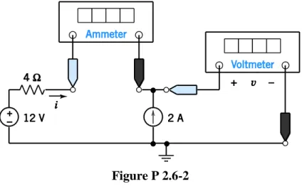
P 2.6-2 The current source in Figure P 2.6-2 supplies 40 W. What values do the meters in Figure P 2.6-2 read?
Figure P 2.6-2
Solution:
The voltmeter current is zero so the ammeter current is equal to the current source current except for the reference direction:
i = -2 A
The voltage v is the voltage of the current source.
The power supplied by the current source is 40 W so
P 2.6-5 The voltmeter in Figure P 2.6-5a measures the voltage across the current source. Figure P 2.6-5b shows the circuit after removing the voltmeter and labeling the voltage measured by the voltmeter as vm. Also, the other element voltages and currents are labeled in Figure P 2.6-5b.
Given that
R m R s
12 v v and i i 2 A
and vR25iR
(a) Determine the value of the voltage measured by the meter.
(b) Determine the power supplied by each element.
Figure P 2.6-5
Solution:
a.)
R 25 R 25 2 50 V
v i
m 12 R 12 50 62 V
v v
b.)
Element Power supplied
voltage source
s
12 i 12 2 24 W
current source 62 2
124 Wresistor
R R 50 2 100 W
v i
P 2.7-1 The ammeter in the circuit shown in Figure P 2.7-1 indicates that ia = 2 A, and the voltmeter indicates that vb = 8 V. Determine the value of r, the gain of the CCVS.
Answer: r = 4 V/A
Figure P 2.7-1 Solution:
8 4 2 b a v r
i
P 2.7-3 The ammeters in the circuit shown in Figure P 2.7-3 indicate that ia = 32 A and ib = 8 A. Determine the value of d, the gain of the CCCS.
Answer: d = 4 A/A
Figure P 2.7-3 Solution:
32 A
8 A ; 32A ; 4
8 A
a
b b a
b i
i d i i d
i
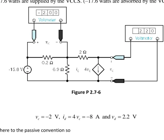
P 2.7-6 Find the power supplied by the VCCS in Figure P 2.7-6.
Answer: 17.6 watts are supplied by the VCCS. (–17.6 watts are absorbed by the VCCS.)
Figure P 2.7-6
Solution:
2 V, 4 8 A and 2.2 V
c d c d
v i v v
id and vd adhere to the passive convention so
(2.2) ( 8) 17.6 W d d
Pv i
DP 2-1 Specify the resistance R in Figure DP 2-1 so that both of the following conditions are satisfied:
1. i > 40 mA.
2. The power absorbed by the resistor is less than 0.5 W.
Figure DP 2-1
Solution:
1.) 10 0 04 10
0 04 250
R . R .
2.) 10 1
2 200
2
R R