Installer/User Guide
Emerson, Emerson Network Power and the Emerson Network Power logo are trademarks or service marks of Emerson Electric Co. Avocent, the Avocent logo, AlterPath, Cyclades, DSR and DSView are trademarks or service marks of Avocent Corporation or its affiliates in the U.S. and other countries. All other marks are the property of their respective owners. This document may contain confidential and/or proprietary information of Avocent Corporation, and its receipt or possession does not convey any right to reproduce, disclose its contents, or to manufacture or sell anything that it may describe. Reproduction, disclosure, or use without specific authorization from Avocent Corporation is strictly prohibited. ©2013 Avocent Corporation. All rights reserved.
T A B L E O F C O N T E N T S
Product Overview 1
System Components 1
Third party products 2
Supported Units 2
Power devices 3
Installation 5
About Installation 5
Minimum requirements for the Rack Power Manager software 5
Before installing and configuring the Rack Power Manager software 6
Installing the Rack Power Manager Software 6
Configuring the Rack Power Manager Software 8
Running the Rack Power Manager Software 9
Minimum client requirements 10
Opening a client session 10
Uninstalling the Rack Power Manager Software 11
Java Installation 12
Transition 15
DSView™ 3 Software and Power Manager Plug-in to RPM software 15
Data Replication 15
Back up the DSView 3 Software 16
Backup the Power Management database 17
Install Rack Power Manager Hub Server 18
Migration Utility 19
Exporting the Data 19
Importing the Data 20
Configure RPM Hub and Spoke servers 22
DSView software to RPM software 22
Data Replication 22
Back up the DSView Software 23
Install Rack Power Manager Hub Server 24
Importing the Data 25
Configure RPM Hub and Spoke server 26
Rack Power Manager Explorer Windows 27
Using the Side Navigation Bar 28
Using Windows 29
Sorting information in a window 29
Filtering information in a window 29
Using the Customize link in windows 30
Displaying pages 32
Printing a window 32
Refreshing a window 32
Using keyboard commands 33
Basic Operations 35
Rack Power Manager Help 35
Configuring the Rack Power Manager help location 35
Installing Rack Power Manager help on a local server 36
Global System Properties 36
Legal Notice 37
PCI Compliance Configuration 37
Power Settings 38
Profiles 39
Changing user options 39
Changing the color scheme 40
Changing your password 40
Choosing the serial session application 40
Specifying a user certificate 41
Specifying an SSH key 42
Enabling user credential caching 42
Internet Explorer Considerations 45
Managing ActiveX® controls 45
Security zones 46
Advanced Internet options 48
Certificates 49
System certificate policy and trust store 50
Integrated Windows Authentication 52
Firewalls 53
VPNs 54
NAT Devices 55
Licenses 57
Adding a new license key 59
System Information 59
Rack Power Manager Servers 61
Server Properties 61
Server certificates 63
Server trap destinations 68
Client session information 69
Email 70
Unit status polling 70
Backing up and Restoring Hub Servers Manually 71
Spoke Servers 74
Replication 78
Authentication Services 81
Supported Authentication Services 81
Rack Power Manager software internal authentication service 82
Active Directory external authentication service 84
Windows NT external authentication service 91
LDAP external authentication service 93
TACACS+ external authentication service 101
RSA SecurID external authentication service 105
User Authentication Services Window 107
Units View Windows 109
Types of Units View windows 109
Topology view 110
Accessing Units View windows 111
Showing and hiding units 112
Units View windows fields 113
Multiple unit operations from a Units View window 115
Unit Overview Windows 116
Unit Status Window 117
Adding and Deleting Units 119
Adding Units 119
Wizards that add units 120
Adding a single managed appliance 120
Adding managed appliances from a range or list of IP addresses 122
Adding a generic appliance 123
Deleting Units 124
Automatically deleting attached units 124
Synchronizing the Rack Power Manager Software Database 125
Name Synchronization 125
Automatic name push 125
Automatic name pull 126
Manual name push 128
Manual name pull 128
Topology Synchronization 129
Automatic topology synchronization 129
Topology synchronization options in the Add Unit Wizard 130
Automatic Inheritance for Group Memberships and Properties 131
Managing Units 133
Appliance Configuration Templates 133
Saving appliance configuration templates 133
Modifying appliance configuration template properties 134
Applying appliance configuration templates 135
Unit Properties 136
Unit Overview Settings 140
About Access Rights 143
How access rights can be assigned 143
Unit Access Rights 144
Managed Appliance Settings 145
Managed Appliance SNMP Settings 147
Bulk Configuration of Individual settings 148
Infrastructure View 149
Asset and Usage Reports 150
Unit Reports 150
Asset 151
Usage 152
Scheduled Reports 152
Segregated Temperature Readings 153
Tiered Energy Cost Setting 154
Power Devices and Power Device Sockets 155
Power Devices 155
Power Device Input Feed 157
Power Device Sockets 158
Power Control of Devices Attached to Power Devices 160
Power Operations 161
Unit Sessions and Connections 163
Customizing the Appliance Sessions window 163 Connections to Units 164 SSH Passthrough Sessions 165 Configuring SSH Passthrough 165 Enabling SSH Passthrough 165 SSH port sharing 166 SSH Passthrough Sessions 167
Establishing an SSH Passthrough connection to a unit 168
Escape key sequence 170
Break sequences 171
Transferring read/write access 172
Disconnecting a session 173
Displaying session output 173
Grouping Units 175
Site, Department and Location Groups 175
Custom Fields 178
Unit Groups 181
Unit group hierarchy 183
Adding or deleting a unit group 186
Changing the unit group properties 187
Custom Groups 190
Adding or deleting a custom group query 190
Changing the custom group properties 191
Changing the custom group rights 191
Custom Group Reports and Scheduled Tasks 192
DS Zones 195
Managing and Accessing Zones 195
Enabling DS Zones 195
Creating zones 195
Transferring units to a zone 197
Managing zone properties 198
Using Zones 200
Units actions in a zone 200
Managing User Accounts 207
User Accounts Windows 207
Adding User Accounts 209
Deleting User Accounts 212
Unlocking User Accounts 212
Resetting a User Account Password 212
Changing User Account Properties 213
Username 213
User certificates 214
User SSH key 214
User password 215
User account restrictions and expiration settings 215
User group membership 216
Address 217
Phone contact 217
Email contact 217
User notes 218
Custom field properties 218
User Access Rights 218
User Groups 221
Adding User-defined User Groups 222
Deleting User-defined User Groups 225
User Group Properties 225
Changing User Group Members 226
User Group Access Rights 227
About the Telnet Viewer 229
Telnet Viewer Window Features 230
Telnet Viewer window toolbar 231
Security Property 232
Opening a Session 233
Customizing the Telnet Viewer 233
Customizing Session Properties 234
Login scripts 237
Reviewing Session Data 238
Macros 239
Macro groups 241
Logging 243
Copying, Pasting and Printing Session Data 246
Power Control of Devices Attached to Power Devices 247
Closing a Telnet Viewer Session 248
Using Tools 249
Using Unit Tools 249
Exporting units 249
Exporting access rights 251
Importing data 252
Using the Managed Appliance Tools 253
Rebooting 253
Upgrading firmware 254
Resynchronizing units 255
Saving a managed appliance configuration 256
Restoring a managed appliance configuration 257
Saving a managed appliance user database 257
Restoring a managed appliance user database 258
Using Tasks 259
Adding tasks 260
Specifying when to run tasks 260
Adding Tasks Using the Add Task Wizard 263
Task: Backup Rack Power Manager software database and system files 263
Task: Configure SNMP trap settings on a managed appliance 264
Task: Exporting an event log .csv file 265
Task: Exporting an Asset Report to a .csv file 267
Task: Exporting a Usage Report to a .csv file 268
Task: Updating the firmware of an appliance type 269
Task: Validating user accounts on an external authentication server 270
Task: Pull names from selected units 270
Task: Update topology for selected units 271
Running tasks manually 272
Displaying task results 273
Deleting tasks 273
Changing tasks 274
Firmware Management 274
Events and Event Logs 277
Event Severity and Categories 277
Event severity 277
Event categories 278
Email Notifications 278
Enabling and Disabling Event Logging 281
Displaying the Event Log 282
Event states 284
Using the date filter 285
Changing the Event Log Retention Period 285
Creating an Event Log .csv File 286
Plug-ins 289
Adding Plug-ins 290
Displaying Plug-in Information 291
Managing Plug-ins 293
Upgrading a plug-in 293
Disabling and activating a plug-in 293
Appendix A: Technical Support 295
Appendix B: Terminal Emulation 296 Appendix C: Regaining Access to the Rack Power Manager Software 314
Product Overview
1
Rack Power Manager software is a stand-alone web browser-based, centralized Rack PDU Management solution. It provides all centralized management capabilities related to Rack PDU devices, ability to perform power control actions as well as run power consumption reports for outlets, PDU's, racks, rows etc. as well as for all custom groups of equipment.
NOTE:Unless otherwise specified, all references to DSView™ software refer to DSView software version 4 or higher.
System Components
The Rack Power Manager software system contains the following components.
Rack Power Manager management software
The Rack Power Manager software resides on the Rack Power Manager server (host or hub computer) and provides a web gateway and services for managing rack PDUs using a web browser.
Users may connect to the Rack Power Manager server from Rack Power Manager software clients and use the Rack Power Manager Explorer windows to communicate with the system.
Rack Power Manager server
The Rack Power Manager server contains the Rack Power Manager management software. The server provides a centralized database for storing configuration, user, unit and system information. It also provides services for authentication, access control, logging events, monitoring and license management.
You may configure one or more spoke (backup) servers in addition to the hub server. The hub server is responsible for maintaining the master copy of the database in a Rack Power Manager software system. Only one server in a Rack Power Manager software system may be configured as the hub server.
Spoke servers are primarily used for redundancy of all PDU management and to have improved scalability. They perform database replication with the hub server. The hub server acts as the coordinator for database replication between itself and all of the other spoke servers in a Rack Power Manager software system. A hub server and a spoke server both offer the same Rack Power Manager software functionality to a user. The distinction of hub or spoke refers only to the database replication role that the server plays and not with the functionality that the server provides. Adding one or more spoke servers to a Rack Power Manager software system provides redundancy and the ability to distribute Rack Power Manager software functionality across multiple sites. Power consumption data is not replicated to all spokes, however, when a report is created it spans across all servers to gather the data.
After the hub server and optional spoke server(s) are configured, you may create and configure the type of access levels for users within your network environment. You may also set up event logs to record full details of user access and other events.
Rack Power Manager software client
A Rack Power Manager software client is a computer with a web browser that can access the Rack Power Manager management software installed on the Rack Power Manager server.
Third party products
Third party products are not a part of the Rack Power Manager software, but are supported for use with it.
• External authentication servers - An external authentication server enables the Rack Power Manager server to broker authentication requests from users requesting access to the Rack Power Manager software system.
• SNMP managers - The SNMP (Simple Network Management Protocol) manager monitors the managed appliances and receives SNMP traps from the Rack Power Manager software on the server. An example of an SNMP manager is the HP OpenView product.
• Third party Telnet viewers - A third party Telnet viewer may be used for serial sessions instead of the Rack Power Manager software Telnet Viewer.
Supported Units
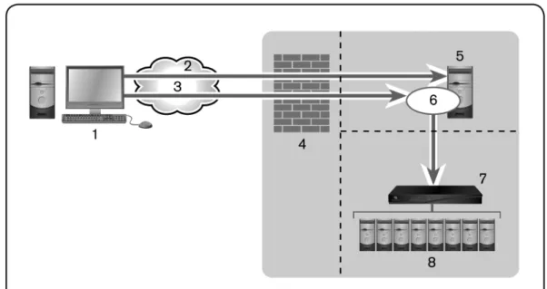
For management functions, the Rack Power Manager software client uses HTTPS (Hypertext Transfer Protocol with SSL encryption) to send a request to the Rack Power Manager server, which then sends a command to the managed appliance. The appliance then performs the requested function.
The Rack Power Manager software supports the managed appliances listed in this section. Other appliances may be supported by plug-ins; see the Avocent web site, www.avocent.com, for a list of plug-ins that may currently ship with the Rack Power Manager software and/or that can be added to the Rack Power Manager software. SeePlug-inson page 289 for information about adding and managing plug-ins in the Rack Power Manager software system.
Power devices
The Rack Power Manager software supports the following power devices: • Avocent SPC power control devices
• Server Technologies Sentry Switched CDU CW-8H1, CW-8H2, CW-16V1, CW-16V2, CW-24V2, CW-24V3, CW-32VD1 and CW-32VD2 (supported models may change; contact Avocent Technical Support for current information)
• Cyclades™Intelligent Power Distribution Unit (AlterPath™manager)
• Avocent Power Management Distribution Unit (PM PDU) PM 1000/2000/3000 PDUs • Liebert MPH/MPX units
• APC 78xx/79xx PDUs
All of the above power devices are supported on DSR™ KVM over IP switches that contain one or more SPC ports. Server Technologies power devices are also supported when connected through Avocent appliances.
Avocent models are supported when connected serially or through an Avocent appliance or directly over the network. Liebert and APC models are supported only when connected directly through the network.
Installation
2
This chapter describes the installation sequence for the Rack Power Manager software: • What you should do before installing the software
• How to install the software
• Configuring the software, plus considerations when upgrading • Starting a client session
Final sections describe how to change your password, uninstall the software, end a Rack Power Manager software session and install Java.
About Installation
When the Rack Power Manager software is installed, the RPM software database is installed on the dedicated server.
Rebooting the dedicated server is not required prior to using the Rack Power Manager software. Once the Rack Power Manager software is installed and you have configured the hub server, users may log in as a Rack Power Manager software client, using a supported web browser. You may also install the Rack Power Manager software on additional computers and configure them as spoke servers. SeeSpoke Serverson page 74
NOTE:A license key permits the operation of the Rack Power Manager software on the dedicated server. The license key also specifies the number of clients that may use the software.
Minimum requirements for the Rack Power Manager software
Visit http://www.avocent.com/software-requirements for the minimum requirements for installing the Rack Power Manager software on a dedicated hub or spoke server.
Before installing and configuring the Rack Power Manager software
Before installing the Rack Power Manager software, install the managed appliance hardware. If the computer will be a hub server, you will need the license key obtained from Emerson and provide a username and password to use for initial log in.
If the computer will be a spoke server, you will need to identify the associated hub server and provide the name/password of the hub server’s Rack Power Manager software administrator.
Installing the Rack Power Manager Software
The Rack Power Manager software can be installed on a physical server or VM and the installation instructions described in this section apply to both scenarios. The Rack Power Manager management software may be installed using the Rack Power Manager software DVD or by downloading the software in a self-extracting .zip file from the Avocent web site.
To install the Rack Power Manager software:
1. Log on to the dedicated server as Administrator or root. 2. To install from a DVD:
a. Insert the Rack Power Manager software DVD. An autorun file opens a menu of installation options.
b. ClickInstall Rack Power Manager Software.
-or-For Windows, if autorun is not enabled, type<drive:>\RPM\win32\setup.exe, where <drive:> is the letter of your DVD drive.
A dialog box will indicate that the server will be verified to ensure it meets the minimum requirements for installing the Rack Power Manager software. For Linux, issue the following command to mount the DVD volume:mount <device> <mount point>, where <device> and <mount point> are the names of your server’s DVD Linux device and mount point directory, respectively. For example, to mount the first IDE cdrom on /media/cdrom, enter the command:mount /dev/cdrom /media/cdrom
3. To install from a downloaded file:
a. Using your web browser, download the Rack Power Manager software from the Avocent web site. Go to www.avocent.com and click theSupportlink. On the Technical Support page, click theProduct Upgradeslink, then selectRPM Software Upgrades.
b. Double-click on the downloaded installation package (setup.exe). A dialog box will indicate that the server will be verified to ensure it meets the minimum requirements for installing the Rack Power Manager software.
c. For Linux, enter the following command to access the readme file:less /<mount point>/RPM/readme. For example, the following command accesses the readme file on the /media/cdrom mount point.
less /media/cdrom/Rack Power Manager/readme
4. If the current version of the Rack Power Manager software is already installed, the Installed Product Found: Same Version message box will appear. ClickOKto reinstall the Rack Power Manager software orCancelto exit setup.
5. The Check for an UPDATED version window will open. (If the Rack Power Manager software is already installed on the dedicated server, a message box will display. ClickOK to close the box.)
a. ClickNextto reinstall the software, or clickCancelto stop the reinstallation.
b. ClickCheck for UPDATESand then click Nextto check the Avocent web site for the most recent Rack Power Manager software installation package. Go to step 5.
-or-ClickNextto install the DVD or downloaded version of the Rack Power Manager software. Go to step 6.
6. If a newer version of the Rack Power Manager software is found, an Update Available message appears.
a. ClickOKto download the latest Rack Power Manager software installation package. The installation will be cancelled and the server’s default web browser will launch and open in the Product Upgrades and Options page of the Avocent web site.
-or-ClickCancelto resume installation of the older version of the Rack Power Manager software. Go to step 6.
b. Type your email address and password, and then clickSubmitto log in to the web site. c. Download the Rack Power Manager software installation package, log out and close
the web browser. Return to step 2.
7. The Introduction window will open. Follow the on screen instructions.
8. For a new database installation, click Next to install a new PostgreSQL database. a. Choose a location to install the database.
b. Enter the port number. c. Enter the password. d. Click Install.
9. For an existing database installation, click the checkbox to Use Existing Database. 10. Click Next.
a. Entert the database IP address, listening port number and the database username and password.
b. On the Installation Settings Confirmation screen, click Install. 11. The Installation Complete window will open.
• To begin configuration of the Rack Power Manager software, clickDone; see Configuring the Rack Power Manager Softwareon page 8. A Security Alert dialog box will appear containing certificate information and a warning that the generator of the certificate is not trusted. This occurs because the Rack Power Manager server certificate created when the server is installed is a self-signed certificate. You may either import the certificate into the Rack Power Manager software client web browser (choosing to trust the certificate) or obtain a server certificate from a Certificate Authority (CA) trusted by the web browser.
• To configure the Rack Power Manager software at a later time, clickX(Cancel)in the top right corner of the window.
Configuring the Rack Power Manager Software
After the Rack Power Manager software has been installed, it must be configured using a web browser.
During configuration, you specify whether the computer will be a hub server or a spoke server. If this is your first Rack Power Manager server installation,hubshould be selected in the Select RPM Server Role window. The hub server should be installed before any spoke servers are added.
To configure the Rack Power Manager software:
1. If you are configuring the Rack Power Manager software during the installation process, you have already clickedDonein the Launch Default Browser window.
If you quit after installing the Rack Power Manager software installation process (by closing the window), selectStart - Programs - Emerson Rack Power Manager - RPM Software.
2. A security alert box will appear containing certificate information. SeeCertificateson page 49.
3. The Select RPM Server Role window opens.
• ClickHubto assign the dedicated server as the hub server, then clickNext. Go to step 4.
• ClickSpoketo assign the dedicated server as a spoke server, then clickNext. Go to step 8.
4. Follow the on screen instructions. 5. ClickFinish.
6. The User Login window will open in the Rack Power Manager Explorer.
You may now log in using the username and password specified during configuration. If you chose to configure the server as a spoke server in the Select RPM Server Role window or if you entered a duplicate software license key in the Type in Master License Key window, continue with the following steps.
7. The Type in Hub Server Address and Port window will open. Type the address of the Rack Power Manager software hub server using standard dot notation (xxx.xxx.xxx.xxx) or type the DNS name in the Address field. ClickNext.
8. The Accept Rack Power Manager Server Certificate window will open. ClickNextto accept the certificate.
9. The Type in Hub Administrator Credentials window will open. Type a valid username and password for a user with Rack Power Manager software administrator privileges on the Rack Power Manager software hub server. ClickNext.
10. The Registering Spoke Server window will open with the messageRequest In Progress Please WaitThe configuration of the spoke server will be saved to the database of the hub server and the spoke server’s certificates will be installed on the hub server.
11. The Completed Successful window will open when the spoke server has been added. Click Finish.
Running the Rack Power Manager Software
Rack Power Manager software clients access the Rack Power Manager software host using a supported web browser. Any software required by the client, such as applets and the Java Runtime Environment (JRE), will be automatically installed by the Rack Power Manager server host.
The Rack Power Manager software uses Secure Sockets Layers (SSL) encryption to send data between the Rack Power Manager software host and the web browser on the client to ensure data integrity and privacy. When a user attempts to log in to a Rack Power Manager software client session, the authentication service configured in the Rack Power Manager software by the Rack Power Manager software administrator verifies the credentials of the user. Security alerts related to the certificates on the Rack Power Manager software host may appear. See Certificateson page 49.
Minimum client requirements
Visit http://www.avocent.com/software-requirements for minimum client requirements.
Opening a client session
Before opening a client session
• Enable cookies and JavaScript on the client’s web browser.
• Configure the web browser. If you are using Internet Explorer, seeInternet Explorer Considerationson page 45.
To open a client session:
NOTE:If Rack Power Manager Software Client Certificate Authentication or Rack Power Manager Software Client Integrated Windows Authentication is being used, the user will not be required to log in. SeeCertificateson page 49.
1. From the Rack Power Manager software client web browser, enter the URL of the server host in the address bar in the format:
https://<servername>/RPM
In this case, <servername> is the DNS name of the host system, or the IP address in standard dot notation (xxx.xxx.xxx.xxx).
NOTE:To avoid multiple security warnings, enter the DNS name.
-or-If you are opening the session on the Rack Power Manager server, you may selectStart - Programs - Emerson Rack Power Manager - RPM Software.
2. Accept all security alerts that may appear as the client computer connects to the Rack Power Manager server. The Rack Power Manager Explorer User Login window will open. If an RSA SecurID external authentication service has been added to the Rack Power Manager software, seeRSA SecurID loginon page 11 below for the login procedure. 3. Type a valid username and password in the fields provided.
Depending on the settings specified by the administrator, you may be required to change your password before being allowed to complete the login process. SeeAdding User Accountson page 209.
4. ClickLogin. The window that appears depends on the rights assigned to the Rack Power Manager user that is logging in.
If the client machine uses an onboard video controller and experiences video problems, be sure the BIOS is updated to the latest version.
RSA SecurID login
When an RSA SecurID external authentication service has been added to the Rack Power Manager software, the login credentials include a username and a passcode. The passcode includes a PIN and an RSA SecurID tokencode. The login request is sent to the RSA Authentication Manager. Depending on the user configuration and state on the RSA Authentication Manager, the user may be prompted for a second successive tokencode. The user configuration also specifies how the four to six digit PIN will be generated: • User defined - the user must enter a PIN
• System generated - the user cannot enter a PIN; it must be generated by the RSA server • User selectable - the user may choose to enter a PIN or allow the RSA server to generate it If a PIN has not yet been assigned to the user or if security policy requires a PIN change, the user will be prompted accordingly. If the RSA server generates the PIN, the user will be given a brief interval to memorize it.
Uninstalling the Rack Power Manager Software
To uninstall the Rack Power Manager software on a supported Windows system:
1. SelectStart - Settings - Control Panel. The Control Panel will appear.
2. From the Control Panel, clickAdd/Remove Programs. The Add/Remove Programs dialog box will appear.
3. SelectEmerson Rack Power Managerand then clickChange/Remove. The Uninstall Avocent RPM window will open.
4. ClickUninstall.
To uninstall the Rack Power Manager software on a supported Linux system:
2. Insert the Rack Power Manager software DVD into your DVD drive. If AutoMount is supported and enabled, open a command window and continue with step 3.
-or-If your system does not support AutoMount, issue the following command to mount the DVD volume:mount <device> <mount point>, where <device> and <mount point> are the names of your server’s DVD Linux device and mount point directory, respectively.
For example, to mount a DVD which is the second IDE unit on /media/cdrom, enter the command:
mount /dev/cdrom /media/cdrom
3. Enter the following command to access the readme file.
less /media/cdrom/RPM/readme
Follow the instructions in the readme file.
To close a Rack Power Manager software session:
From the Rack Power Manager Explorer, clickLOGOUTor the logout icon.
Java Installation
On non-Windows clients, Telnet requires Java version 1.5. The Telnet/SSH applet may work with other versions.
On Windows clients, Java is required to run the Emerson Telnet/SSH Viewer. If the Win32 PuTTY Telnet/SSH Viewer is selected in the user’s profile, then Java is not required on the client. On a Windows client, it is recommended that the JRE (Java Runtime Environment) be installed in the C:\Program Files\ location.
To configure Java to find the JRE:
1. Access the Java Control Panel. 2. Select theJavatab.
3. In the Java Application Runtime Settings panel, clickView. 4. Change the path to the installed JRE.
5. ClickOK.
For Windows and Linux operating systems, the Rack Power Manager software client automatically downloads and installs the JRE the first time it is needed. For Macintosh
operating systems, you must update Java and install the JRE using the Macintosh software updates. Refer to the Macintosh operating system documentation for more information.
To install the JRE on a Windows client:
1. In a Rack Power Manager software Units View window (seeAccessing Units View windowson page 111), click an Action link.
2. A window will open, containing a link for downloading the JRE installer. Download the JRE installer, then close all browser windows.
3. Click on the JRE icon to launch the installer. 4. Restart the browser, and click an Action link.
To install the JRE on a Linux client:
NOTE:Only one version of the JRE can be installed in the browser for Rack Power Manager software support. Depending on your system’s configuration, you may have to log in as the root user to install the JRE. Contact your system administrator if you need help with installing software as the root user.
1. In a Rack Power Manager software Units View window (seeAccessing Units View windowson page 111), click an Action link.
2. A window will open, containing a link for downloading the JRE installer. Download the JRE installer, then close all browser windows.
3. Run the installer.
Transition
3
This chapter describes the steps for transitioning to Rack Power Manager software.
• Transitioning from DSView 3 management software and DSView 3 Power Manager Plug-in to Rack Power Manager software
• Transitioning from DSView software version 4 or higher to the Rack Power Manager software
DSView™ 3 Software and Power Manager Plug-in to RPM
software
NOTE:In this document, DSView 3 software refers to DSView software versions 3.7.2.x or 3.7.3.x.
NOTE:In order to safely upgrade to the RPM software, and to provide a roll-back path in case of upgrade failures, perform each of the following steps. If your DSView 3 configuration does not include spoke servers, skip the steps that refer to spoke servers.
Before you begin, ensure that you budget sufficient time to transition the hub and spoke servers concurrently.
Data Replication
Perform a replication of all DSView 3 software spoke servers. In order to ensure that the entire system has fully replicated, run the replication task twice to ensure that all spokes are in sync with the hub server.
To initiate an immediate replication on a spoke server:
1. On the spoke server, click theSystemtab.
2. ClickTasksin the top navigation bar. The Tasks window will open.
Back up the DSView 3 Software
Using the DSView 3 software backup and restore utility or the command line, back up the hub and each spoke server. The backup includes the database, plug-ins, firmware, appliance templates and system properties. You may manually create a backup of your hub server. Two methods are available:
• From a command line in an MS-DOS window. This method may be used for DSView 3 software hub servers on supported Windows® systems.
• Use the Backup and Restore system task located in the DSView 3 software WebUI. The backup is saved as a .zip file containing the files needed to restore the DSView 3 management software. This method may be used for DSView 3 software hub servers on supported Windows® systems only.
Client sessions will be temporarily disconnected during a manual backup. The sessions will be automatically reconnected when the backup is completed.
Manual backup and restore procedures require DSView 3 software administrator privileges.
To manually back up a hub server using a command line on a supported Windows system:
1. In the Start menu on your desktop, selectStart - Programs - Accessories - Command Prompt. A command prompt window will open.
2. Change directories to the directory in which the DSView 3 software is installed (typically C:\Program Files\Avocent DSView 3\bin).
3. EnterDSViewBackupRestoreto display the DSView 3 Backup and Restore Utility dialog box.
4. To back up the DSView 3 software hub server, enterDSViewBackupRestore backup -archive “<-archive name>” -passwd <password>.
For example, entering the following in a command prompt window will create a backup named db.zip with the password test.
DSViewBackupRestore.exe -backup -archive “db.zip” -passwd test
To manually back up a hub server using a command line on a supported Linux system:
1. Access the command prompt on your system.
2. Change directories to the directory where the DSView 3 software is installed, which is typically /usr/local/dsviewserver/bin.
3. To backup the DSView 3 software hub server, enterDSViewBackupRestore.sh backup -archive <-archive name> -passwd <password> -overwrite.
For example, entering the following in a command prompt window will create a backup named dbasebackup.zip with the password test1.
DSViewBackupRestore.sh backup -archive dbasebackup.zip -passwd test1
To manually back up a hub server using the Backup and Restore Utility dialog box on a supported Windows system:
1. In the Start menu on your desktop, selectStart - Programs - Avocent DSView 3- Backup and Restore Utility. The DSView 3 Backup/Restore Utility dialog box will appear. 2. ClickBackup Database to a file.
3. To password-protect the backup file, clickEnabledand type a password in the Password field.
4. ClickBrowseand use the Save As dialog box to specify a directory and name for the backup file. ClickSavewhen you are finished.
5. ClickBackup. The DSView 3software system backup files are saved. 6. ClickCloseto close the DSView 3 Backup/Restore Utility dialog box.
Backup the Power Management database
This task creates a folder containing a backup of the Power Manager database. The backup folder is named dsviewPluginBackup;<SYSTEM NAME> by default, but you may also append the date and time to the end of the backup folder. Run this task on each of the hub and spoke servers.
To configure the PMP backup:
1. Click theSystemtab.
2. ClickTasksin the top navigation bar. The Tasks window will open. 3. ClickAdd. The Add Task Wizard will appear.
4. SelectBackup Power Manager databasefrom the drop-down menu. Type a 1-64 character name for the task.
5. Select a time to run the task, then clickNext.
6. The Specify Power Manager Database Backup Properties window will open. a. Type the directory location in which to create the backup file, which may be a
a UNC (Universal Naming Convention) path. The Location field cannot be set to a mapped network drive. The directory name must be entered in case sensitive text if your operating system supports case sensitive filenames.
b. If the specified directory location is a network path that requires a login, enable the Login required to access shared drive locationcheckbox. Then type the username and password and confirm the password of a user account that has read/write access to the network share location.
c. To append the date and time (in military time) to the end of the system backup folder, enable theUse date and time for folder namingcheckbox. For example, if you are creating the backup folder on October 1, 2005 at 10:04 pm, the folder created will be named dsviewBackup1001052204;<Machine Name>.
If a backup folder already exists in the specified directory and theUse date and time for folder namingoption is not enabled, the existing backup folder will be overwritten when the new backup folder is created.
7. ClickFinish.
8. Navigate to the etc folder of this backup folder. Compress the etc folder into a zip file manually. Use the zip of etc folder in all subsequent steps that require the backup of a Power Management database.
Install Rack Power Manager Hub Server
To Install RPM Software:
1. Download the latest version of RPM software to the server. 2. Run the installation file.
3. ClickNextto continue with the installation.
4. Accept the terms of the License Agreement, clickNext. 5. ClickNexton the Installation Settings screen.
6. Choose the RPM software installation location and clickNext.
7. Review the default RPM software TCP Port Settings tab, make any changes needed and clickNext.
8. On the PostgreSQL Installation screen, check the box to Use Existing Database if connecting to an existing and clickNext.
-or
9. For an existing PostgreSQL server, enter the IP address, port, username and password and clickNext.
-or
-For a new instance, enter the install folder, port, and password and clickNext. Click Installon the confirmation screen.
10. ClickOkon the Service Startup message. 11. ClickDone.
Migration Utility
Exporting the Data
The DSView data migration utility was installed with the RPM software. It will allow you to convert from the embedded DSView PMP database to PostgreSQL data format.
To export the DSView 3 backup data into PostgreSQL format from a Windows operating system:
1. To launch the migration utility, from the Windows server, clickStart All Programs -Emerson - RPM1.0 - DSViewDataMigrationUtility.
2. On the Export tab, select the Server Type from the drop-down menu. a. ChooseHub, if you are exporting data from the hub.
b. ChooseSpokeif you are exporting data from the spoke.
3. SelectDSViewfor the Database Type from the drop-down menu when you are specifying a DSView Software backup.
-or-SelectPMPfor the Database Type from the drop-down menu when you are specifying backup of the Power Management database. If you have both DSView Software backup and Power Management database backup, you will have to run the utility twice to select both the options.
4. In the field Data Backup File Path, enter the path or browse to the location of the DSView Software backup or PMP database backup file. If using a PMP database backup file, this is the zip file of the etc folder that was created previously.
5. In the Migration File Path field, enter or browse to the location that you will save the exported file.
To export the DSView 3 software data from a Linux® operating system:
1. Navigate to the DSViewDataMigrationUtility folder, By default this folder is located at /usr/local/Emerson/RackPowerManager/DSViewDataMigrationUtility. To launch the migration utility, enter./DataMig.shfrom the command line.
2. Choose option number two to export the data. 3. From the menu, enter the server type.
a. ChooseHub, if you are exporting data from the hub. b. ChooseSpokeif you are exporting data from the spoke.
4. SelectDSViewfor the Database Type when you are specifying a DSView software backup.
-or-SelectPMPfor the Database Type when you are specifying backup of the Power Management database. If you have both DSView software backup and Power
Management database backup, you will have to run the utility twice to select both the options.
5. Input the location of the DSView Software backup or PMP database backup file. If using a PMP database backup file, this is the zip file of the etc folder that was created previously. 6. Input the location to save the Migration File.
7. Verify the settings and enterYto continue with the export.
Importing the Data
The RPM data migration utility migrates the exported data you get from the previous steps into the RPM database.
To Import DSView or DSView + PMP database from a Windows Operating System:
1. To launch the migration utility, from the Windows server, clickStart All Programs -Emerson - RPM1.0 - RPMDataMigrationUtility.
2. ClickNextto continue.
3. SelectDSView3+PMP to RPM 1.0and clickNext.
4. Enter the server IP address of the RPM software hub server.
5. Enter the listening port for your hub database server in the DB Server Port field. 6. Enter the database username in the Username field.
7. Enter the password for the database in the Password field. 8. Enter the database name in the DB Name field.
9. ClickNext.
10. In the DSView Hub Database field, enter or browse to the location that you saved the DSView 3 software export file.
11. In the PMP Database field, enter the path or browse to the location of the exported PMP database file.
12. ClickNext.
13. Assign the data from servers on your DSView System to your RPM System and clickNext. 14. Confirm the server assignments and clickNext.
15. In case you have assigned data to RPM spoke server, you will be prompted for the DB server port, user name and password of the spoke DB server. Enter these details and click Next.
16. ClickFinish.
To Import PMP Database from a Linux Operating System:
1. Navigate to the RPMDataMigrationUtility folder. By default this folder is located at /usr/local/Emerson/RackPowerManager/RPMDataMigrationUtility. To launch the migration utility, enter ./DBMigration.shfrom the command line.
2. ClickNextto continue.
3. SelectDSView3+PMP to RPM 1.0and clickNext.
4. Enter the server IP address of the RPM software hub server.
5. Enter the listening port for your hub database server in the DB Server Port field. 6. Enter the database username in the Username field.
7. Enter the password for the database in the Password field. 8. Enter the database name in the DB Name field.
9. ClickNext.
10. In the DSView Hub Database field, enter or browse to the location that you saved the DSView 3 software export file.
11. In the PMP Database field, enter the path or browse to the location of the exported PMP database file.
12. ClickNext.
14. Confirm the server assignments and clickNext.
15. In case you have assigned data to RPM spoke server, you will be prompted for the DB server port, user name and password of the spoke DB server. Enter these details and click Next.
16. ClickFinish.
Configure RPM Hub and Spoke servers
To configure the hub server:
1. Stop the RPM service on the hub server.
2. Copy the backed up firmware, appliance templates and system properties over to the corresponding folders on the hub server.
3. Restart the hub server.
To configure the spoke server(s):
1. Stop the RPM service on the spoke service.
2. Copy the backed up firmware, appliance templates and system properties over to the corresponding folders on the spoke server.
3. Restart the spoke server.
4. Run data replication on each spoke server.
DSView software to RPM software
The section describes how to transition to RPM software from DSView software version 4 or higher. Before you begin, ensure that you budget sufficient time to transition the hub and spoke servers concurrently.
Data Replication
Perform a replication of all DSView software spoke servers. In order to ensure that the entire system has fully replicated, run the replication task twice to ensure that all spokes are in sync with the hub server.
To initiate an immediate replication on a spoke server:
1. On the spoke server, click theSystemtab.
2. ClickTasksin the top navigation bar. The Tasks window will open.
Back up the DSView Software
Using the DSView software backup and restore utility or the command line, back up the hub and each spoke server. The backup includes the database, plug-ins, appliance templates and system properties. You may manually create a backup of your hub server. Two methods are available:
• From a command line in an MS-DOS window. This method may be used for DSView software hub servers on supported Windows® systems.
• Use the Backup and Restore system task located in the DSView software WebUI. The backup is saved as a .zip file containing the files needed to restore the DSView software. This method may be used for DSView software hub servers on supported Windows® systems only.
Client sessions will be temporarily disconnected during a manual backup. The sessions will be automatically reconnected when the backup is completed.
Manual backup and restore procedures require DSView software administrator privileges.
To manually back up a hub server using a command line on a supported Linux system:
1. Access the command prompt on your system.
2. Change directories to the directory where the DSView software is installed, which is typically /usr/local/dsviewserver/bin.
3. To backup the DSView software hub server, enterDSViewBackupRestore.sh backup -archive <-archive name> -passwd <password> -overwrite.
For example, entering the following in a command prompt window will create a backup named dbasebackup.zip with the password test1.
DSViewBackupRestore.sh backup -archive dbasebackup.zip -passwd test1
To manually back up a hub server using the Backup and Restore Utility dialog box on a supported Windows system:
1. In the Start menu on your desktop, selectStart - Programs - Avocent DSView - Backup and Restore Utility. The DSView Backup/Restore Utility dialog box will appear.
2. ClickBackup Database to a file.
3. To password-protect the backup file, clickEnabledand type a password in the Password field.
4. ClickBrowseand use the Save As dialog box to specify a directory and name for the backup file. ClickSavewhen you are finished.
5. ClickBackup. The DSView software system backup files are saved. 6. ClickCloseto close the DSView Backup/Restore Utility dialog box.
Extract the PostgreSQL data file
To extract PostgreSQL data file:1. Decompress the backup file previously generated.
2. Navigate to the bin folder and copy the postgresbackup.tar file to another location. This file will have to be used as input to import the data to the Rack Power Manager software.
Install Rack Power Manager Hub Server
To Install RPM Software:1. Download the latest version of RPM software to the server. 2. Run the installation file.
3. ClickNextto continue with the installation.
4. Accept the terms of the License Agreement, clickNext. 5. ClickNexton the Installation Settings screen.
6. Choose the RPM software installation location and clickNext.
7. Review the default RPM software TCP Port Settings tab, make any changes needed and clickNext.
8. On the PostgreSQL Installation screen, check the box to Use Existing Database if connecting to an existing and clickNext.
-or
-ClickNextto install a new instance.
9. For an existing PostgreSQL server, enter the IP address, port, username and password and clickNext.
-or
-For a new instance, enter the install folder, port, and password and clickNext. Click Installon the confirmation screen.
10. ClickOkon the Service Startup message. 11. ClickDone.
Importing the Data
To Import DSView database from a Windows Operating System:
1. To launch the migration utility, from the Windows server, clickStart All Programs -Emerson - RPM1.0 - RPMDataMigrationUtility.
2. ClickNextto continue.
3. Select DSView4 to RPM 1.0 and clickNext.
4. Enter the server IP address of the RPM software hub server.
5. Enter the listening port for your hub server in the DB Server Port field. 6. Enter the database name in the DB Name field.
7. Enter the database username in the Username field. 8. Enter the password for the database in the Password field.
9. Browse or enter the location of the DSView4 Database in the DSView4 DB field. This is the postgresbackup.tar file that was extracted from the DSView4 backup
10. ClickNext.
11. Assign the servers for migration and clickNext. 12. Confirm the server assignments and clickNext. 13. ClickFinish.
To Import DSView Database from a Linux Operating System:
1. Navigate to the RPMDataMigrationUtility folder. By default, this folder is located at /usr/local/Emerson/RackPowerManager/RPMDataMigrationUtility. To launch the migration utility, enter./DBMigration.shfrom the command line.
2. ClickNextto continue.
3. Select DSView4 to RPM 1.0 and clickNext.
4. Enter the server IP address of the RPM software hub server.
5. Enter the listening port for your hub server in the DB Server Port field. 6. Enter the database name in the DB Name field.
7. Enter the database username in the Username field. 8. Enter the password for the database in the Password field.
9. Browse or enter the location of the DSView4 Database in the DSView4 DB field. This is the postgresbackup.tar file that was extracted from the DSView4 backup
10. ClickNext.
11. Assign the servers for migration and clickNext. 12. Confirm the server assignments and clickNext. 13. ClickFinish.
Configure RPM Hub and Spoke server
To configure the hub server:
1. Stop the RPM service on the hub server.
2. Copy the backed up firmware, appliance templates and system properties over to the corresponding folders on the hub server.
3. Restart the hub server.
To configure the spoke server(s):
1. Stop the RPM service on the spoke service.
2. Copy the backed up firmware, appliance templates and system properties over to the corresponding folders on the spoke server.
3. Restart the spoke server.
Rack Power Manager Explorer
Windows
4
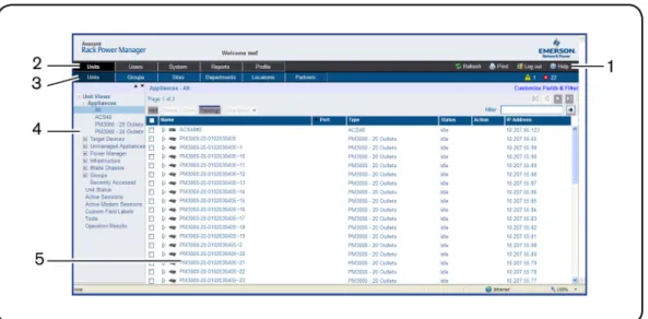
When a user is logged in and authenticated, the Emerson Rack Power Manager Explorer window opens. From the Rack Power Manager Explorer window, you may view, access and manage units.
Figure 4.1: Example EmersonRack Power Manager Explorer Window Areas
Number Description
1
Top option bar - Use the top option bar to bookmark a Rack Power Manager software window, refresh a window display, print a page, log out of a software session or access online help. The name of the logged in user appears on the left side of the top option bar.
2 Tab bar - Use the tab bar to display and manage units, user accounts, reports, system settings and
session profiles.
3 Top navigation bar - The selections in the top navigation bar vary, depending on the active tab in the
tab bar. Topics relevant to each selection display in the side navigation bar.
4 Side navigation bar - Use the side navigation bar to select system information to display or edit in the
content area. The side navigation bar contains arrows that affect its display.
5 Content area - The information specified by the tab bar, top navigation bar and side navigation bar
selections is displayed and changed in the content area.
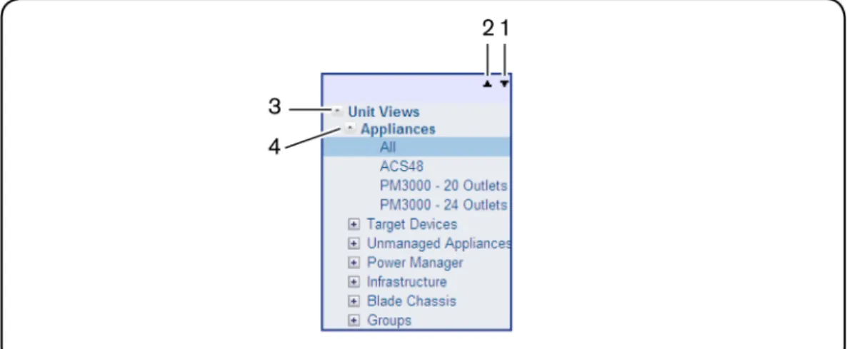
Using the Side Navigation Bar
The side navigation bar is used to display windows that specify settings or perform operations. The contents of the side navigation bar varies, depending on the tab and top navigation bar selections and the window that is displayed.
Figure 4.2: Example Side Navigation Bar
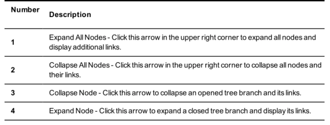
Number
Description
1 Expand All Nodes - Click this arrow in the upper right corner to expand all nodes and
display additional links.
2 Collapse All Nodes - Click this arrow in the upper right corner to collapse all nodes and
their links.
3 Collapse Node - Click this arrow to collapse an opened tree branch and its links.
4 Expand Node - Click this arrow to expand a closed tree branch and display its links.
You may choose whether an expanded node will collapse when another Expand Node arrow is selected. SeeChanging user optionson page 39.
Using Windows
Sorting information in a window
The order of rows in a list may be changed by clicking the heading of one of the displayed columns. When you click a column heading, the order of the list rows will change to
alphabetically ascending, based on that column. If you click the column heading a second time, the order will change to an alphabetically descending order.
If you are using the topology feature in a Units View window, seeTopology viewon page 110 for sorting criteria.
Filtering information in a window
Some Rack Power Manager software windows allow you to filter list information by providing a text string that will be used to retrieve matching items.
When filtering, you may use an asterisk (*) before and/or after text strings as a wildcard. For example, typingemailserver*and clicking Filterwill display items with emailserver at the beginning (such as emailserver, emailserverbackup). Typing*emailserver*and clickingFilter will display items containing emailserver in any part of the name (such as emailserver, emailserverstore, tdemailserver, tdemailserver1).
Table 4.3 lists the ways you may specify text strings for filtering. Table 4.3: Filter Text Strings
Typed in the Filter Field Results
<String>
Entering a string displays a filtered list of items that contain the ‘word’ (that is, it will find matching strings that are followed by anything other than a letter or number). For example, typingemailwill list any items that contain the string email, followed by a space or punctuation mark. If you enter multiple words sep-arated by spaces but without logical operators, OR is assumed, and each word is treated separately. For example, typingemail serverwill display items con-taining email or server.
"<String>"
Surrounding the string with quotation marks displays a filtered list of items con-taining the exact string, including spacing and punctuation. For example, typing
"email server”will display items that contain email server. The Rack Power Manager software will provide a closing quotation mark if it is omitted. <String1> AND <String2>
Using the AND logical operator displays the items that contain both strings. For example, typingemail and serverwill display items named email-server-3, email-server-2, server email and so on.
<String1> OR <String2>
Using the OR logical operator displays the items that contain at least one of the strings. For example, typingemail or serverwill find any items that contain the string email or the string server.
(<String>)
Parentheses may be used to override the default (left to right) order of prec-edence during evaluation of a filter string. For example, searching foremail and server or servicewould be the equivalent of ((email and server) or serv-ice), which may not be the intended search. The user may choose instead to change the order of precedence by grouping the search terms with paren-theses, such as(email) and (server or service).
NOT <String>
Preceding the string with NOT displays all items that do not contain the string. For example, typingnot emailwill display all items except those containing email (email, email server, email-server-1 and so on will not display).
Using the Customize link in windows
Windows that contain aCustomizeorCustomize Fields and Filterlink allow you to change the following information:
• The number of items displayed per page in the window
• Which columns of information are displayed in Units View windows
• Which columns are included in a filter from a Units View window (available from the Customize Fields and Filter link only)
By clicking theCustomizelink, you can also show units that have been hidden in a Units View window.
NOTE:If you are in a Units View window, the link is displayed as “Custom Fields and Filter” and this window contains additional filtering options. On any other window, the link is displayed as “Customize”. The term “Customize link” is used throughout this document to refer to both links.
The items available for customizing and methods for changing them will vary, depending on the window being customized. Although the items that appear in windows may vary, the items that do appear are modified identically regardless of the window in which you clicked the Customizelink.
To customize a window using the Customize link:
1. In a window containing a Customize link in the upper right corner, click the link. A View Customization window will open.
2. Add, remove or move fields in the window display:
• To add one or more fields to the window display, select the fields in the Available Fields list, then clickAdd. The fields will be moved to the Fields to Show list. • To remove one or more fields from the window display, select the fields in the Fields
to Show list, then clickRemove. The fields will be moved to the Available Fields list. • To change the order that fields display from left to right in the window, select one or
more fields in the Fields to Show list. Use the up or down arrow to change its order in the list.
3. To specify the number of items that appear in a window, use the arrow keys in the Items per Page field to select a number or type a number (1-2000). In Units View windows that have the topology view enabled, the number of items per page includes children, even if the display is collapsed and the children are not visible.
4. To show hidden items in a Units View window (seeShowing and hiding unitson page 112).
a. Check theShow hidden itemscheckbox.
b. SelectVisibilityfrom the Available Fields column, and then clickAdd.Visibility will move to the Fields to Show list.
5. To show group descendants in windows that display unit groups (seeUnit group hierarchy on page 183), click theShow group descendantscheckbox.
6. To expand a topology view automatically in a Units View window (seeTopology viewon page 110), click theExpand view automaticallycheckbox.
7. (Units View windows only) To specify which fields are included in a filter, select the field (s) from the Available Fields list and click theAdd button. To remove fields from a filter, select the fields from theFilteron these fields list and clickRemove.
8. To set the Fields to Show and List Items as the default, clickSet as Default. This button will appear only if you are a Rack Power Manager software administrator. You will be prompted to confirm setting these values as the default. Confirm or cancel.
9. ClickSaveand then clickFinish. The window being customized will open with the changes.
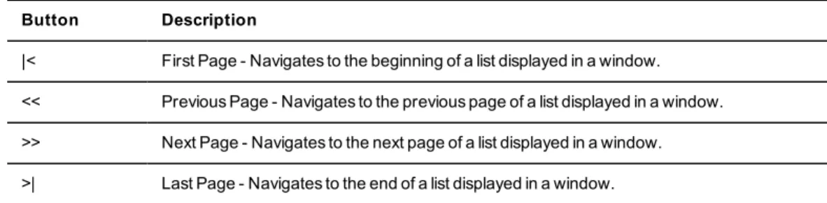
Displaying pages
Multiple page windows contain navigation buttons which may be used to quickly move among pages.
Table 4.4: Rack Power Manager Explorer Page Navigation Buttons
Button Description
|< First Page - Navigates to the beginning of a list displayed in a window. << Previous Page - Navigates to the previous page of a list displayed in a window. >> Next Page - Navigates to the next page of a list displayed in a window. >| Last Page - Navigates to the end of a list displayed in a window.
Printing a window
All windows contain a print icon and text in the top option bar. When you print a window, all the information on the page is printed, not just the visible portion.
To print a window:
1. In the top option bar, clickPRINTor the print icon. The Print dialog box will appear. 2. Specify options to use, then clickPrintto print the window and close the Print dialog box.
Refreshing a window
A window may be refreshed at any time by clickingREFRESHor the refresh icon in the top option bar.
By default, status information automatically refreshes every 30 seconds. This interval may be changed or disabled. SeeChanging user optionson page 39.
Using keyboard commands
In addition to using a mouse, certain keyboard commands may be used to select and change items in windows.
Table 4.5: General Keyboard Commands
Key Description
Tab Transfers focus to the next control in the window, including the calendar Shift-Tab Transfers focus to the previous HTML control
Table 4.6 lists the keyboard commands that may be used when a calendar is enabled and has focus.
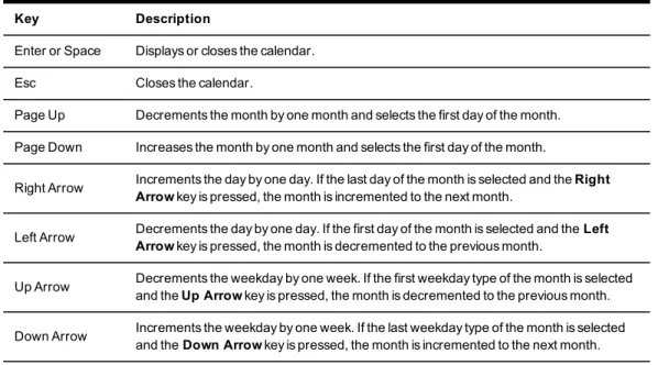
Table 4.6: Calendar Keyboard Commands
Key Description
Enter or Space Displays or closes the calendar. Esc Closes the calendar.
Page Up Decrements the month by one month and selects the first day of the month. Page Down Increases the month by one month and selects the first day of the month.
Right Arrow Increments the day by one day. If the last day of the month is selected and theRight
Arrowkey is pressed, the month is incremented to the next month.
Left Arrow Decrements the day by one day. If the first day of the month is selected and theLeft
Arrowkey is pressed, the month is decremented to the previous month.
Up Arrow Decrements the weekday by one week. If the first weekday type of the month is selected and theUp Arrowkey is pressed, the month is decremented to the previous month. Down Arrow Increments the weekday by one week. If the last weekday type of the month is selected
and theDown Arrowkey is pressed, the month is incremented to the next month.
Table 4.7 lists the keyboard commands that may be used when a spinner is enabled and has focus.
Key Description
Up Arrow Increments the spinner number by one Down Arrow Decrements the spinner number by one