Manual
WAGO-I/O-SYSTEM 750
ETHERNET TCP/IP 2-port Controller
750-871
PLC - ETHERNET TCP/IP Programmable Fieldbus
Controller, 2 Ports
750-871 ETHERNET TCP/IP 2-port Controller
© 2014 by WAGO Kontakttechnik GmbH & Co. KG All rights reserved.
WAGO Kontakttechnik GmbH & Co. KG
Hansastraße 27 D-32423 Minden Phone: +49 (0) 571/8 87 – 0 Fax: +49 (0) 571/8 87 – 1 69 E-Mail: [email protected] Web: http://www.wago.com Technical Support Phone: +49 (0) 571/8 87 – 5 55 Fax: +49 (0) 571/8 87 – 85 55 E-Mail: [email protected]
Every conceivable measure has been taken to ensure the accuracy and completeness of this documentation. However, as errors can never be fully excluded, we always appreciate any information or suggestions for improving the documentation.
E-Mail: [email protected]
We wish to point out that the software and hardware terms as well as the trademarks of companies used and/or mentioned in the present manual are generally protected by trademark or patent.
750-871 ETHERNET TCP/IP 2-port Controller
Pos : 5 /D okument ati on allgemein/Verzeic hnisse/I nhalts verz eichnis - Ü berschrif t oG und Verzei chnis @ 3\ mod_1219151230875_21. doc x @ 21063 @ @ 1
Table of Contents
1 Notes about this Documentation ... 12
1.1 Validity of this Documentation ... 12
1.2 Copyright ... 12 1.3 Symbols ... 13 1.4 Number Notation ... 15 1.5 Font Conventions ... 15 2 Important Notes ... 16 2.1 Legal Bases ... 16 2.1.1 Subject to Changes ... 16 2.1.2 Personnel Qualifications ... 16
2.1.3 Use of the WAGO-I/O-SYSTEM 750 in Compliance with Underlying Provisions ... 16
2.1.4 Technical Condition of Specified Devices ... 17
2.2 Safety Advice (Precautions) ... 18
2.3 Special Use Conditions for ETHERNET Devices ... 20
3 System Description... 21
3.1 Manufacturing Number ... 22
3.2 Hardware Address (MAC ID) ... 22
3.3 Component Update ... 23
3.4 Storage, Assembly and Transport ... 23
3.5 Assembly Guidelines/Standards ... 24 3.6 Power Supply ... 25 3.6.1 Isolation ... 25 3.6.2 System Supply ... 26 3.6.2.1 Connection ... 26 3.6.2.2 Dimensioning ... 27 3.6.3 Field Supply... 30 3.6.3.1 Connection ... 30 3.6.3.2 Fusing ... 32
3.6.4 Supplementary Power Supply Regulations ... 35
3.6.5 Supply Example... 36
3.6.6 Power Supply Unit ... 38
3.7 Grounding ... 39
3.7.1 Grounding the DIN Rail ... 39
3.7.1.1 Framework Assembly ... 39 3.7.1.2 Insulated Assembly ... 39 3.7.2 Grounding Function... 40 3.8 Shielding ... 41 3.8.1 General ... 41 3.8.2 Bus Cables ... 41 3.8.3 Signal Lines ... 42
3.8.4 WAGO Shield Connecting System ... 42
4 Device Description ... 43
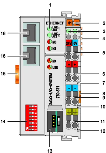
4.1 View ... 46
750-871 ETHERNET TCP/IP 2-port Controller 4.2.1 Device Supply ... 48 4.2.2 Fieldbus Connection ... 49 4.3 Display Elements ... 50 4.4 Operating Elements ... 52 4.4.1 Service Interface ... 52
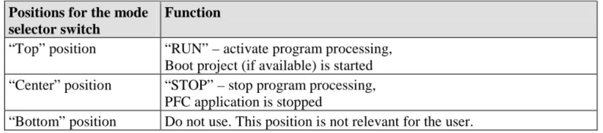
4.4.2 Mode Selector Switch... 53
4.4.3 Address Selection Switch ... 55
4.5 Technical Data ... 56 4.5.1 Device Data ... 56 4.5.2 System Data ... 56 4.5.3 Supply ... 57 4.5.4 Fieldbus MODBUS/TCP ... 57 4.5.5 Accessories ... 57 4.5.6 Connection Type ... 57
4.5.7 Climatic Environmental Conditions ... 58
4.5.8 Mechanical Strength acc. to IEC 61131-2 ... 58
4.6 Approvals ... 59
4.7 Standards and Guidelines ... 61
5 Mounting ... 62
5.1 Installation Position ... 62
5.2 Overall Configuration ... 62
5.3 Mounting onto Carrier Rail ... 64
5.3.1 Carrier Rail Properties ... 64
5.3.2 WAGO DIN Rail ... 65
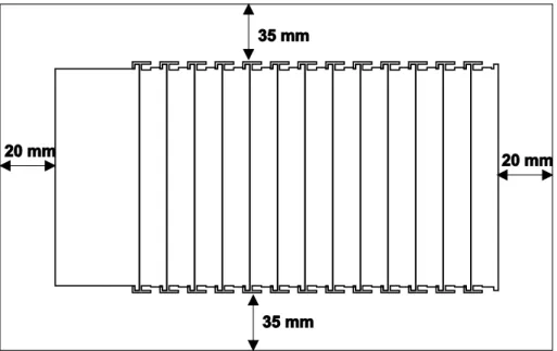
5.4 Spacing ... 65
5.5 Mounting Sequence ... 66
5.6 Inserting and Removing Devices ... 67
5.6.1 Inserting the Fieldbus Coupler/Controller ... 68
5.6.2 Removing the Fieldbus Coupler/Controller ... 68
5.6.3 Inserting the I/O Module ... 69
5.6.4 Removing the I/O Module ... 70
6 Connect Devices ... 71
6.1 Data Contacts/Internal Bus ... 71
6.2 Power Contacts/Field Supply ... 72
6.3 Connecting a Conductor to the CAGE CLAMP® ... 73
7 Function Description ... 74
7.1 Operating System ... 74
7.1.1 Run-up ... 74
7.1.2 PFC Cycle ... 74
7.2 Process Data Architecture ... 76
7.2.1 Basic Structure... 76
7.2.2 Example of an Input Process Image ... 78
7.2.3 Example of an Output Data Process Image ... 79
7.2.4 Process Data MODBUS/TCP and EtherNet/IP ... 80
750-871 ETHERNET TCP/IP 2-port Controller
7.3.2.2 IEC-61131-3 Address Areas ... 87
7.3.2.3 Absolute Addressing ... 88
7.3.3 Data Exchange between MODBUS/TCP Master and I/O Modules ... 90
7.3.4 Data Exchange between EtherNet/IP Master and I/O Modules ... 91
7.3.5 Data Exchange between PLC Function (CPU) and I/O Modules ... 92
7.3.6 Data Exchange between Master and PLC Function (CPU) ... 93
7.3.6.1 Example of MODBUS/TCP Master and PLC Function (CPU) .... 93
7.3.7 Application Example ... 95
8 Commissioning ... 96
8.1 Connecting Client PC and Fieldbus Nodes ... 97
8.2 Allocating the IP Address to the Fieldbus Node ... 97
8.2.1 Assigning IP Address via WAGO-ETHERNET-Settings ... 98
8.2.2 Assigning IP Address via Address Selection Switch ... 99
8.2.3 Assigning IP Address via DHCP ... 101
8.2.3.1 Enable DHCP ... 101
8.2.3.2 Disabling DHCP ... 102
8.2.4 Assigning the IP Address with a BootP Server ... 108
8.2.4.1 Note MAC ID ... 109
8.2.4.2 Determining IP addresses ... 111
8.2.4.3 Assigning the IP address ... 112
8.2.4.4 Disabling BootP ... 112
8.2.4.5 Reasons for Failed IP Address Assignment ... 117
8.3 Testing the Function of the Fieldbus Node ... 118
8.4 Preparing the Flash File System ... 120
8.5 Synchronizing the Real-Time Clock ... 122
8.6 Restoring Factory Settings ... 125
9 Programming the PFC using WAGO-I/O-PRO ... 126
9.1 Configuring the Fieldbus Controller using the I/O Configurator ... 129
9.1.1 Configuration using the “EA-config.xml” File ... 131
9.2 ETHERNET Libraries for WAGO-I/O-PRO ... 133
9.3 Functional Restrictions and Limits ... 135
9.4 General Information about IEC Tasks ... 137
9.4.1 IEC Task Sequence... 139
9.4.2 Overview of Most Important Task Priorities... 139
9.5 System Events ... 141
9.5.1 Enabling/disabling system events... 141
9.6 Transfer the IEC program to the controller ... 143
9.6.1 Transfer via Serial Service Port ... 144
9.6.2 Transfer via ETHERNET ... 147
10 Configuring via the Web-Based Management System (WBM) ... 149
10.1 Information ... 151 10.2 Ethernet ... 153 10.3 TCP/IP ... 157 10.4 Port ... 158 10.5 SNMP ... 160 10.5.1 SNMP V1/V2c... 161 10.5.2 SNMP V3 ... 163 10.6 Watchdog ... 165
750-871 ETHERNET TCP/IP 2-port Controller 10.7 Clock ... 167 10.8 Security ... 169 10.9 PLC Info ... 172 10.10 PLC Settings ... 173 10.11 Features ... 176 10.12 I/O Config ... 177 10.13 Disk Info ... 180 10.14 WebVisu ... 181 11 Diagnostics ... 183 11.1 LED Signaling ... 183
11.1.1 Evaluating Fieldbus Status ... 183
11.1.2 Evaluating Node Status – I/O LED (Blink Code Table) ... 185
11.1.2.1 USR LED ... 194
11.1.3 Evaluating Power Supply Status ... 195
11.2 Fault Behavior ... 196
11.2.1 Loss of Fieldbus ... 196
11.2.2 Internal Data Bus Failure... 197
12 Fieldbus Communication ... 198
12.1 General ETHERNET Information ... 198
12.1.1 Network Architecture – Principles and Regulations ... 200
12.1.1.1 Transmission Media ... 201
12.1.1.2 Network Topologies ... 203
12.1.1.3 Coupler Modules ... 205
12.1.1.4 ETHERNET - Transmission Mode ... 206
12.1.1.5 Important Terms ... 208
12.1.2 Network Communication ... 210
12.1.2.1 ETHERNET- Packet ... 210
12.1.2.2 ETHERNET address (MAC-ID) ... 210
12.1.2.3 Channel access method ... 211
12.1.3 Protocol layer model (Example) ... 212
12.1.4 Communication Protocols ... 215
12.1.4.1 IP (Internet Protocol) ... 215
12.1.4.2 TCP (Transmission Control Protocol) ... 219
12.1.4.3 UDP (User Datagram Protocol) ... 220
12.1.5 Configuration and Diagnostics Protocols ... 221
12.1.5.1 BootP (Bootstrap Protocol) ... 221
12.1.5.2 HTTP (Hypertext Transfer Protocol) ... 222
12.1.5.3 DHCP (Dynamic Host Configuration Protocol) ... 223
12.1.5.4 DNS (Domain Name Systems) ... 225
12.1.5.5 SNTP-Client (Simple Network Time Protocol) ... 225
12.1.5.6 FTP-Server (File Transfer Protocol) ... 226
12.2 SNMP (Simple Network Management Protocol) ... 228
12.2.1 MIB II Description ... 229
12.2.2 Description of the WAGO-MIB ... 230
750-871 ETHERNET TCP/IP 2-port Controller
12.3.3 Description of the MODBUS Functions ... 238
12.3.3.1 Function Code FC1 (Read Coils) ... 239
12.3.3.2 Function Code FC2 (Read Discrete Inputs) ... 241
12.3.3.3 Function Code FC3 (Read Multiple Registers) ... 243
12.3.3.4 Function Code FC4 (Read Input Registers) ... 244
12.3.3.5 Function Code FC5 (Write Coil) ... 245
12.3.3.6 Function Code FC6 (Write Single Register) ... 246
12.3.3.7 Function Code FC11 (Get Comm Event Counter) ... 247
12.3.3.8 Function Code FC15 (Write Multiple Coils) ... 248
12.3.3.9 Function Code FC16 (Write Multiple Registers) ... 250
12.3.3.10 Function Code FC22 (Mask Write Register) ... 251
12.3.3.11 Function Code FC23 (Read/Write Multiple Registers) ... 252
12.3.4 MODBUS Register Mapping ... 254
12.3.5 MODBUS Registers ... 257
12.3.5.1 Accessing Register Values ... 259
12.3.5.2 Watchdog Registers ... 259
12.3.5.3 Diagnostic Registers ... 265
12.3.5.4 Configuration Registers ... 266
12.3.5.5 Firmware Information Registers ... 271
12.3.5.6 Constant Registers ... 273
12.4 EtherNet/IP (Ethernet/Industrial Protocol) ... 275
12.4.1 General ... 275
12.4.2 Protocol overview in the OSI model ... 276
12.4.3 Characteristics of the EtherNet/IP Protocol Software ... 277
12.4.4 EDS File ... 277
12.4.5 Object Model ... 278
12.4.5.1 General ... 278
12.4.5.2 Class Overview ... 279
12.4.5.3 Explanation of the Table Headings in the Object Descriptions ... 281
12.4.5.4 Identity (01 hex) ... 281
12.4.5.5 Message Router (02 hex) ... 283
12.4.5.6 Assembly Object (04 hex) ... 284
12.4.5.7 Port Class (F4 hex) ... 288
12.4.5.8 TCP/IP Interface (F5 hex) ... 290
12.4.5.9 Ethernet Link (F6 hex)... 291
12.4.5.10 Coupler/Controller Configuration (64 hex) ... 297
12.4.5.11 Discrete Input Point (65 hex) ... 300
12.4.5.12 Discrete Input Point Extended 1 (69 hex)... 300
12.4.5.13 Discrete Input Point Extended 2 (6D hex) ... 301
12.4.5.14 Discrete Input Point Extended 3 (71 hex)... 302
12.4.5.15 Discrete Output Point (66 hex) ... 302
12.4.5.16 Discrete Output Point Extended 1 (6A hex) ... 303
12.4.5.17 Discrete Output Point Extended 2 (6E hex) ... 304
12.4.5.18 Discrete Output Point Extended 3 (72 hex) ... 304
12.4.5.19 Analog Input Point (67 hex) ... 305
12.4.5.20 Analog Input Point Extended 1 (6B hex) ... 306
12.4.5.21 Analog Input Point Extended 2 (6F hex) ... 306
12.4.5.22 Analog Input Point Extended 3 (73 hex) ... 307
12.4.5.23 Analog Output Point (68 hex) ... 308
750-871 ETHERNET TCP/IP 2-port Controller
12.4.5.25 Analog Output Point Extended 2 (70 hex) ... 309
12.4.5.26 Analog Output Point Extended 3 (74 hex) ... 310
12.4.5.27 Module Configuration (80 hex) ... 311
12.4.5.28 Module Configuration Extended (81 hex) ... 311
12.4.5.29 Input Fieldbus Variable USINT (A0 hex) ... 312
12.4.5.30 Input Fieldbus Variable USINT Extended 1 (A1 hex) ... 314
12.4.5.31 Input Fieldbus Variable USINT Extended 2 (A2 hex) ... 315
12.4.5.32 Output Fieldbus Variable USINT (A3 hex) ... 316
12.4.5.33 Output Fieldbus Variable USINT Extended 1 (A4 hex) ... 317
12.4.5.34 Output Fieldbus Variable USINT Extended 2 (A5 hex) ... 318
12.4.5.35 Input Fieldbus Variable UINT (A6 hex) ... 319
12.4.5.36 Input Fieldbus Variable UINT Extended 1 (A7 hex) ... 320
12.4.5.37 Output Fieldbus Variable UINT (A8 hex) ... 321
12.4.5.38 Output Fieldbus Variable UINT Extended 1 (A9 hex) ... 322
12.4.5.39 Input Fieldbus Variable UDINT (AA hex) ... 323
12.4.5.40 Input Fieldbus Variable UDINT Offset (AB hex) ... 324
12.4.5.41 Output Fieldbus Variable UDINT (AC hex) ... 325
12.4.5.42 Output Fieldbus Variable UDINT Offset (AD hex) ... 326
13 I/O Modules ... 327
13.1 Overview ... 327
13.2 Process Data Architecture for MODBUS/TCP ... 328
13.2.1 Digital Input Modules... 329
13.2.1.1 1 Channel Digital Input Module with Diagnostics ... 329
13.2.1.2 2 Channel Digital Input Modules ... 329
13.2.1.3 2 Channel Digital Input Module with Diagnostics ... 329
13.2.1.4 2 Channel Digital Input Module with Diagnostics and Output Process Data ... 330
13.2.1.5 4 Channel Digital Input Modules ... 330
13.2.1.6 8 Channel Digital Input Modules ... 330
13.2.1.7 8 Channel Digital Input Module PTC with Diagnostics and Output Process Data ... 331
13.2.1.8 16 Channel Digital Input Modules ... 331
13.2.2 Digital Output Modules ... 332
13.2.2.1 1 Channel Digital Output Module with Input Process Data ... 332
13.2.2.2 2 Channel Digital Output Modules ... 332
13.2.2.3 2 Channel Digital Input Modules with Diagnostics and Input Process Data ... 333
13.2.2.4 4 Channel Digital Output Modules ... 334
13.2.2.5 4 Channel Digital Output Modules with Diagnostics and Input Process Data ... 334
13.2.2.6 8 Channel Digital Output Module ... 334
13.2.2.7 8 Channel Digital Output Modules with Diagnostics and Input Process Data ... 335
13.2.2.8 16 Channel Digital Output Modules ... 335
13.2.2.9 8 Channel Digital Input/Output Modules ... 336
750-871 ETHERNET TCP/IP 2-port Controller
13.2.3.5 8 Channel Analog Input Modules ... 340
13.2.4 Analog Output Modules ... 341
13.2.4.1 2 Channel Analog Output Modules ... 341
13.2.4.2 4 Channel Analog Output Modules ... 341
13.2.4.3 8 Channel Analog Output Modules ... 342
13.2.5 Specialty Modules ... 343
13.2.5.1 Counter Modules ... 343
13.2.5.2 Pulse Width Modules ... 345
13.2.5.3 Serial Interface Modules with alternative Data Format ... 345
13.2.5.4 Serial Interface Modules with Standard Data Format ... 346
13.2.5.5 Data Exchange Module ... 346
13.2.5.6 SSI Transmitter Interface Modules ... 346
13.2.5.7 Incremental Encoder Interface Modules ... 347
13.2.5.8 DC-Drive Controller ... 349
13.2.5.9 Stepper Controller ... 350
13.2.5.10 RTC Module ... 351
13.2.5.11 DALI/DSI Master Module ... 351
13.2.5.12 DALI Multi-Master Module ... 352
13.2.5.13 LON® FTT Module ... 354
13.2.5.14 EnOcean Radio Receiver ... 354
13.2.5.15 MP Bus Master Module ... 354
13.2.5.16 Bluetooth® RF-Transceiver ... 355
13.2.5.17 Vibration Velocity/Bearing Condition Monitoring VIB I/O ... 356
13.2.5.18 KNX/EIB/TP1 Module ... 356
13.2.5.19 AS-interface Master Module ... 357
13.2.6 System Modules ... 359
13.2.6.1 System Modules with Diagnostics ... 359
13.2.6.2 Binary Space Module ... 359
13.3 Process Data Architecture for EtherNet/IP ... 360
13.3.1 Digital Input Modules... 361
13.3.1.1 1 Channel Digital Input Module with Diagnostics ... 361
13.3.1.2 2 Channel Digital Input Modules ... 361
13.3.1.3 2 Channel Digital Input Module with Diagnostics ... 362
13.3.1.4 2 Channel Digital Input Module with Diagnostics and Output Process Data ... 362
13.3.1.5 4 Channel Digital Input Modules ... 363
13.3.1.6 8 Channel Digital Input Modules ... 363
13.3.1.7 16 Channel Digital Input Modules ... 363
13.3.2 Digital Output Modules ... 364
13.3.2.1 1 Channel Digital Output Module with Input Process Data ... 364
13.3.2.2 2 Channel Digital Output Modules ... 365
13.3.2.3 2 Channel Digital Input Modules with Diagnostics and Input Process Data ... 365
13.3.2.4 4 Channel Digital Output Modules ... 366
13.3.2.5 4 Channel Digital Output Modules with Diagnostics and Input Process Data ... 366
13.3.2.6 8 Channel Digital Output Module ... 367
13.3.2.7 8 Channel Digital Output Modules with Diagnostics and Input Process Data ... 367
750-871 ETHERNET TCP/IP 2-port Controller
13.3.2.9 8 Channel Digital Input/Output Modules ... 368
13.3.3 Analog Input Modules ... 369
13.3.3.1 1 Channel Analog Input Modules ... 369
13.3.3.2 2 Channel Analog Input Modules ... 370
13.3.3.3 4 Channel Analog Input Modules ... 370
13.3.3.4 4 Channel Analog Input Modules for RTD’s ... 370
13.3.3.5 3-Phase Power Measurement Module ... 370
13.3.3.6 8 Channel Analog Input Modules ... 371
13.3.4 Analog Output Modules ... 371
13.3.4.1 2 Channel Analog Output Modules ... 372
13.3.4.2 4 Channel Analog Output Modules ... 372
13.3.4.3 8 Channel Analog Output Modules ... 373
13.3.5 Specialty Modules ... 373
13.3.5.1 Counter Modules ... 373
13.3.5.2 Pulse Width Modules ... 375
13.3.5.3 Serial Interface Modules with alternative Data Format ... 376
13.3.5.4 Serial Interface Modules with Standard Data Format ... 376
13.3.5.5 Data Exchange Module ... 377
13.3.5.6 SSI Transmitter Interface Modules ... 377
13.3.5.7 Incremental Encoder Interface Modules ... 378
13.3.5.8 DC-Drive Controller ... 380
13.3.5.9 Steppercontroller ... 381
13.3.5.10 RTC Module ... 382
13.3.5.11 DALI/DSI Master Module ... 383
13.3.5.12 EnOcean Radio Receiver ... 383
13.3.5.13 MP Bus Master Module ... 384
13.3.5.14 Bluetooth® RF-Transceiver ... 384
13.3.5.15 Vibration Velocity/Bearing Condition Monitoring VIB I/O ... 385
13.3.5.16 AS-interface Master Module ... 386
13.3.6 System Modules ... 387
13.3.6.1 System Modules with Diagnostics ... 387
13.3.6.2 Binary Space Module ... 387
14 Application Examples ... 388
14.1 Test of MODBUS protocol and fieldbus nodes ... 388
14.2 Visualization and Control using SCADA Software ... 388
15 Use in Hazardous Environments ... 391
15.1 Marking Configuration Examples ... 392
15.1.1 Marking for Europe According to ATEX and IEC-Ex ... 392
15.1.2 Marking for America According to NEC 500 ... 397
15.2 Installation Regulations ... 398
15.2.1 Special Conditions for Safe Use (ATEX Certificate TÜV 07 ATEX 554086 X) ... 399
15.2.2 Special Conditions for Safe Use (ATEX Certificate TÜV 12 ATEX 106032 X) ... 400
750-871 ETHERNET TCP/IP 2-port Controller 16 Appendix ... 404 16.1 MIB II Groups ... 404 16.1.1 System Group ... 404 16.1.2 Interface Group ... 405 16.1.3 IP Group ... 407
16.1.4 IpRoute Table Group ... 408
16.1.5 ICMP Group ... 409
16.1.6 TCP Group... 410
16.1.7 UDP Group ... 411
16.1.8 SNMP Group ... 412
16.2 WAGO MIB Groups ... 413
16.2.1 Company Group ... 413
16.2.2 Product Group ... 413
16.2.3 Versions Group ... 414
16.2.4 Real Time Clock Group... 414
16.2.5 Ethernet Group ... 415
16.2.6 Actual Error Group ... 415
16.2.7 Error History Group ... 416
16.2.8 PLC Project Group ... 416
16.2.9 Http Group ... 417
16.2.10 Ftp Group... 417
16.2.11 Sntp Group... 418
16.2.12 Snmp Group... 418
16.2.13 Snmp Trap String Group ... 421
16.2.14 Snmp User Trap String Group ... 422
16.2.15 Plc Connection Group ... 422
16.2.16 Modbus Group ... 423
16.2.17 Ethernet IP Group ... 424
16.2.18 Process Image Group ... 425
16.2.19 Plc Data Group ... 426
List of Figures ... 427
List of Tables ... 430
750-871 ETHERNET TCP/IP 2-port Controller
Pos : 7 / Alle Serien (Allgemeine M odul e)/Übersc hrift en für all e Serien/Hi nweis e zur D okument ati on/Hinweise z u dies er D okument ation - Ü berschrif t 1 @ 4\ mod_1237987661750_21. doc x @ 29029 @ 1 @ 1
1
Notes about this Documentation
Pos : 8 / Alle Serien (Allgemeine M odul e)/Hinweise z ur Dokumentation/Hi nweis e/Hi nweis : D okument ation auf bewahr en @ 4\mod_1237987339812_21. doc x @ 29026 @ @ 1
Always retain this documentation!
This documentation is part of the product. Therefore, retain the documentation during the entire service life of the product. Pass on the documentation to any subsequent user. In addition, ensure that any supplement to this documentation is included, if necessary.
Pos : 9 / Alle Serien (Allgemeine M odul e)/Übersc hrift en für all e Serien/Hi nweis e zur D okument ati on/G ültig keit sbereic h - Ü berschrif t 2 @ 12\ mod_1338912448776_21.doc x @ 96469 @ 2 @ 1
1.1
Validity of this Documentation
Pos : 10 /Serie 750 ( WAGO-I/ O-SYST EM)/Hi nweis e z ur D okument ati on/ G ültigkeits bereic h/G ültig keits ber eich Dokumentation Koppl er/C ontroller 750- xxxx, ohne Vari antenangabe @ 14\ mod_1358944039400_21.doc x @ 109362 @ @ 1
This documentation is only applicable to the “ETHERNET TCP/IP 2-port Controller” (750-871).
Pos : 11 /Serie 750 ( WAGO-I/ O-SYST EM)/Hi nweis e z ur D okument ati on/Hi nweise/Ac ht ung: Hinweis z ur D okument ati on Koppl er-/Controll er 750- xxxx @ 4\ mod_1239095964296_21.doc x @ 30118 @ @ 1
The product “ETHERNET TCP/IP 2-port Controller” (750-871) shall only be installed and operated according to the instructions in this manual and the system description for the WAGO-I/O-SYSTEM 750.
Consider power layout of the WAGO-I/O-SYSTEM 750!
In addition to these operating instructions, you will also need the system description for the WAGO-I/O-SYSTEM 750, which can be downloaded at www.wago.com. There, you can obtain important information including information on electrical isolation, system power and supply specifications.
Pos : 12.1 /All e Seri en ( Allgemei ne Module)/Hi nweis e zur D okument ati on/Urhebersc hutz ausführlich @ 4\ mod_1235565145234_21.doc x @ 27691 @ 2 @ 1
1.2
Copyright
This Manual, including all figures and illustrations, is copyright-protected. Any further use of this Manual by third parties that violate pertinent copyright
provisions is prohibited. Reproduction, translation, electronic and phototechnical filing/archiving (e.g., photocopying) as well as any amendments require the written consent of WAGO Kontakttechnik GmbH & Co. KG, Minden, Germany. Non-observance will involve the right to assert damage claims.
750-871 ETHERNET TCP/IP 2-port Controller
Pos : 12.3 /All e Seri en ( Allgemei ne Module)/Ü bers chrift en f ür alle Serien/Hinweis e z ur Dokumentation/ Symbol e - Ü bersc hrift 2 @ 13\ mod_1351068042408_21. doc x @ 105270 @ 2 @ 1
1.3
Symbols
Pos : 12.4.1 /All e Serien ( Allgemei ne Module)/ Wic htige Erläut erungen/ Sicherheits- und sons tige Hinweis e/ Gefahr/G ef ahr: _War nung vor Personenschäden allgemei n_ - Erl äuter ung @ 13\ mod_1343309450020_21. doc x @ 101029 @ @ 1
Personal Injury!
Indicates a high-risk, imminently hazardous situation which, if not avoided, will result in death or serious injury.
Pos : 12.4.2 /All e Serien ( Allgemei ne Module)/ Wic htige Erläut erungen/ Sicherheits- und sons tige Hinweis e/ Gefahr/G ef ahr: _War nung vor Personenschäden durc h elektrisc hen Strom_ - Erläut erung @ 13\ mod_1343309694914_21. doc x @ 101030 @ @ 1
Personal Injury Caused by Electric Current!
Indicates a high-risk, imminently hazardous situation which, if not avoided, will result in death or serious injury.
Pos : 12.4.3 /All e Serien ( Allgemei ne Module)/ Wic htige Erläut erungen/ Sicherheits- und sons tige Hinweis e/ Warnung/ Warnung: _Warnung vor Personensc häden allgemei n_ - Erläut erung @ 13\ mod_1343309877041_21.doc x @ 101035 @ @ 1
Personal Injury!
Indicates a moderate-risk, potentially hazardous situation which, if not avoided, could result in death or serious injury.
Pos : 12.4.4 /All e Serien ( Allgemei ne Module)/ Wic htige Erläut erungen/ Sicherheits- und sons tige Hinweis e/ Vorsic ht /Vorsicht: _War nung vor Pers onensc häden allgemein_ - Erläut erung @ 13\ mod_1343310028762_21. doc x @ 101038 @ @ 1
Personal Injury!
Indicates a low-risk, potentially hazardous situation which, if not avoided, may result in minor or moderate injury.
Pos : 12.4.5 /All e Serien ( Allgemei ne Module)/ Wic htige Erläut erungen/ Sicherheits- und sons tige Hinweis e/ Achtung/ Achtung: _War nung vor Sac hsc häden allgemein_ - Erläut erung @ 13\ mod_1343310134623_21.doc x @ 101041 @ @ 1
Damage to Property!
Indicates a potentially hazardous situation which, if not avoided, may result in damage to property.
Pos : 12.4.6 /All e Serien ( Allgemei ne Module)/ Wic htige Erläut erungen/ Sicherheits- und sons tige Hinweis e/ Achtung/ Achtung: _War nung vor Sac hsc häden durc h elektr ost atis che Aufladung_ - Erläut erung @ 13\ mod_1343310227702_21.doc x @ 101044 @ @ 1
Damage to Property Caused by Electrostatic Discharge (ESD)!
Indicates a potentially hazardous situation which, if not avoided, may result in damage to property.
Pos : 12.4.7 /All e Serien ( Allgemei ne Module)/ Wic htige Erläut erungen/ Sicherheits- und sons tige Hinweis e/Hi nweis /Hinweis: _Wic htiger Hi nweis allgemein_ - Erläut erung @ 13\ mod_1343310326906_21. doc x @ 101047 @ @ 1
Important Note!
Indicates a potential malfunction which, if not avoided, however, will not result in damage to property.
750-871 ETHERNET TCP/IP 2-port Controller
Additional Information:
Refers to additional information which is not an integral part of this documentation (e.g., the Internet).
750-871 ETHERNET TCP/IP 2-port Controller
Pos : 12.6 /All e Seri en ( Allgemei ne Module)/Hi nweis e zur D okument ati on/Zahlens yst eme @ 3\ mod_1221059454015_21. doc x @ 21711 @ 2 @ 1
1.4
Number Notation
Table 1: Number Notation
Number Code Example Note
Decimal 100 Normal notation
Hexadecimal 0x64 C notation
Binary '100'
'0110.0100'
In quotation marks, nibble separated with dots (.)
Pos : 12.7 /All e Seri en ( Allgemei ne Module)/Hi nweis e zur D okument ati on/Sc hrift konventi onen @ 3\ mod_1221059521437_21. doc x @ 21714 @ 2 @ 1
1.5
Font Conventions
Table 2: Font Conventions
Font Type Indicates
italic Names of paths and data files are marked in italic-type.
e.g.: C:\Programme\WAGO-I/O-CHECK
Menu Menu items are marked in bold letters.
e.g.: Save
> A greater-than sign between two names means the selection of a menu item from a menu.
e.g.: File > New
Input Designation of input or optional fields are marked in bold letters,
e.g.: Start of measurement range
“Value” Input or selective values are marked in inverted commas.
e.g.: Enter the value “4 mA” under Start of measurement range.
[Button] Pushbuttons in dialog boxes are marked with bold letters in square brackets.
e.g.: [Input]
[Key] Keys are marked with bold letters in square brackets.
e.g.: [F5]
750-871 ETHERNET TCP/IP 2-port Controller
Pos : 14 /All e Seri en (Allgemei ne Module)/Ü berschrif ten f ür alle Serien/ Wichtige Erläut erungen/ Wichtige Erläuter ungen - Übersc hrift 1 @ 4\ mod_1241428899156_21. doc x @ 32170 @ 1 @ 1
2
Important Notes
Pos : 15.1 /All e Seri en ( Allgemei ne Dokumente) ( Allgemei ne Module)/ Wic htige Erläut erungen/ Einl eit ung Wic htige Erläut erungen @ 3\ mod_1221059818031_21. doc x @ 21717 @ @ 1
This section includes an overall summary of the most important safety
requirements and notes that are mentioned in each individual section. To protect your health and prevent damage to devices as well, it is imperative to read and carefully follow the safety guidelines.
Pos : 15.2 /All e Seri en ( Allgemei ne Module)/Ü bers chrift en f ür alle Serien/ Wichtige Erläuter ungenR ec htlic he Gr undlag en - Übersc hrift 2 @ 3\ mod_1221060626343_21. doc x @ 21726 @ 2 @ 1
2.1
Legal Bases
Pos : 15.3 /All e Seri en ( Allgemei ne Dokumente) ( Allgemei ne Module)/ Wic htige Erläut erungen/ Änderungs vor behalt - Ü bers chrift 3 und I nhalt @ 3\ mod_1221060036484_21.doc x @ 21720 @ 3 @ 1
2.1.1
Subject to Changes
WAGO Kontakttechnik GmbH & Co. KG reserves the right to provide for any alterations or modifications that serve to increase the efficiency of technical progress. WAGO Kontakttechnik GmbH & Co. KG owns all rights arising from the granting of patents or from the legal protection of utility patents. Third-party products are always mentioned without any reference to patent rights. Thus, the existence of such rights cannot be excluded.
Pos : 15.4 /Serie 750 (WAGO-I/ O-SYST EM)/ Wic htige Erläut erungen/ Pers onalqualifi kationPers onalqualifi kation 750- xxxx - Ü bersc hrift 3 und I nhalt @ 3\ mod_1224061208046_21. doc x @ 24063 @ 3 @ 1
2.1.2
Personnel Qualifications
All sequences implemented on WAGO-I/O-SYSTEM 750 devices may only be carried out by electrical specialists with sufficient knowledge in automation. The specialists must be familiar with the current norms and guidelines for the devices and automated environments.
All changes to the coupler or controller should always be carried out by qualified personnel with sufficient skills in PLC programming.
Pos : 15.5 /Serie 750 (WAGO-I/ O-SYST EM)/ Wic htige Erläut erungen/ Bes timmungsgemäß e Verwendung Bes ti mmungsgemäße Verwendung 750-xxxx - Ü berschrif t 3 und I nhal t @ 3\ mod_1224064151234_21. doc x @ 24070 @ 3 @ 1
2.1.3
Use of the WAGO-I/O-SYSTEM 750 in Compliance with
Underlying Provisions
Fieldbus couplers, fieldbus controllers and I/O modules found in the modular WAGO-I/O-SYSTEM 750 receive digital and analog signals from sensors and transmit them to actuators or higher-level control systems. Using programmable controllers, the signals can also be (pre-) processed.
The devices have been developed for use in an environment that meets the IP20 protection class criteria. Protection against finger injury and solid impurities up to 12.5 mm diameter is assured; protection against water damage is not ensured. Unless otherwise specified, operation of the devices in wet and dusty
environments is prohibited.
Operating the WAGO-I/O-SYSTEM 750 devices in home applications without further measures is only permitted if they meet the emission limits (emissions of interference) according to EN 61000-6-3. You will find the relevant information
750-871 ETHERNET TCP/IP 2-port Controller
Appropriate housing (per 94/9/EG) is required when operating the WAGO-I/O-SYSTEM 750 in hazardous environments. Please note that a prototype test certificate must be obtained that confirms the correct installation of the system in a housing or switch cabinet.
Pos : 15.6 /All e Seri en ( Allgemei ne Dokumente) ( Allgemei ne Module)/ Wic htige Erläut erungen/T ec hnis cher Z ust and der G eräte - Übersc hrift 3 und Inhalt @ 3\ mod_1221060446109_21. doc x @ 21723 @ 3 @ 1
2.1.4
Technical Condition of Specified Devices
The devices to be supplied ex works are equipped with hardware and software configurations, which meet the individual application requirements. WAGO Kontakttechnik GmbH & Co. KG will be exempted from any liability in case of changes in hardware or software as well as to non-compliant usage of devices. Please send your request for modified and new hardware or software
configurations directly to WAGO Kontakttechnik GmbH & Co. KG.
750-871 ETHERNET TCP/IP 2-port Controller
Pos : 15.8 /All e Seri en ( Allgemei ne Module)/Ü bers chrift en f ür alle Serien/ Wichtige Erläuter ungenSic her hei tshi nweis e - Übersc hrift 2 @ 6\ mod_1260180299987_21. doc x @ 46724 @ 2 @ 1
2.2
Safety Advice (Precautions)
Pos : 15.9 /All e Seri en ( Allgemei ne Dokumente) ( Allgemei ne Module)/ Wic htige Erläut erungen/ Sicherheits hi nweis e/ Einl eitung Sicherheits hinweis e H ardware @ 6\ mod_1260180170493_21.doc x @ 46720 @ @ 1
For installing and operating purposes of the relevant device to your system the following safety precautions shall be observed:
Pos : 15.10. 1 / Alle Serien (Allgemeine D okument e) (Allgemeine M odul e)/ Wichtige Erläuter ungen/Sic herheits hinweise/G ef ahr /G ef ahr: Nicht an G erät en unter Spannung ar beit en! @ 6\ mod_1260180365327_21. doc x @ 46727 @ @ 1
Do not work on devices while energized!
All power sources to the device shall be switched off prior to performing any installation, repair or maintenance work.
Pos : 15.10. 2 / Serie 750 ( WAG O-I/O- SYST EM)/Wic htig e Erl äuter ung en/Sic her hei ts- und s onstige Hi nweise/G ef ahr/ Gefahr: Ei nbau 0750- xxxx nur i n Gehäus en, Sc hränken oder el ektrisc hen Betriebsräumen! @ 6\ mod_1260180556692_21.doc x @ 46731 @ @ 1
Install the device only in appropriate housings, cabinets or in electrical operation rooms!
The WAGO-I/O-SYSTEM 750 and its components are an open system. As such, install the system and its components exclusively in appropriate housings,
cabinets or in electrical operation rooms. Allow access to such equipment and fixtures to authorized, qualified staff only by means of specific keys or tools.
Pos : 15.10. 3 / Alle Serien (Allgemeine D okument e) (Allgemeine M odul e)/ Wichtige Erläuter ungen/Sic herheits hinweise/G ef ahr /G ef ahr: Unfall verhüt ungs vorsc hrift en beachten! @ 6\ mod_1260180657000_21.doc x @ 46735 @ @ 1
Pos : 15.10. 4 / Alle Serien (Allgemeine D okument e) (Allgemeine M odul e)/ Wichtige Erläuter ungen/Sic herheits hinweise/G ef ahr /G ef ahr: Auf normg erec ht en Ansc hluss ac ht en! @ 6\mod_1260180753479_21.doc x @ 46739 @ @ 1 Pos : 15.11. 1 / Alle Serien (Allgemeine D okument e) (Allgemeine M odul e)/ Wichtige Erläuter ungen/Sic herheits hinweise/Ac ht ung/Ac ht ung: Defekt e oder besc hädigt e Ger ät e aus tausc hen! @ 6\mod_1260180857358_21. doc x @ 46743 @ @ 1
Replace defective or damaged devices!
Replace defective or damaged device/module (e.g., in the event of deformed contacts), since the long-term functionality of device/module involved can no longer be ensured.
Pos : 15.11. 2 / Alle Serien (Allgemeine D okument e) (Allgemeine M odul e)/ Wichtige Erläuter ungen/Sic herheits hinweise/Ac ht ung/Ac ht ung: G eräte vor kriec henden und is olier enden Stoff en schüt zen! @ 6\ mod_1260181036216_21. doc x @ 46747 @ @ 1
Protect the components against materials having seeping and insulating properties!
The components are not resistant to materials having seeping and insulating properties such as: aerosols, silicones and triglycerides (found in some hand creams). If you cannot exclude that such materials will appear in the component environment, then install the components in an enclosure being resistant to the above-mentioned materials. Clean tools and materials are imperative for handling devices/modules.
Pos : 15.11. 3 / Alle Serien (Allgemeine D okument e) (Allgemeine M odul e)/ Wichtige Erläuter ungen/Sic herheits hinweise/Ac ht ung/Ac ht ung: Rei nigung nur mit zul ässigen M at erialien! @ 6\ mod_1260181203293_21.doc x @ 46751 @ @ 1
Clean only with permitted materials!
Clean soiled contacts using oil-free compressed air or with ethyl alcohol and leather cloths.
750-871 ETHERNET TCP/IP 2-port Controller
Do not use any contact spray!
Do not use any contact spray. The spray may impair contact area functionality in connection with contamination.
Pos : 15.11. 5 / Alle Serien (Allgemeine D okument e) (Allgemeine M odul e)/ Wichtige Erläuter ungen/Sic herheits hinweise/Ac ht ung/Ac ht ung: Verpol ung ver mei den! @ 6\ mod_1260184045744_21.doc x @ 46767 @ @ 1
Do not reverse the polarity of connection lines!
Avoid reverse polarity of data and power supply lines, as this may damage the devices involved.
Pos : 15.11. 6 / Alle Serien (Allgemeine D okument e) (Allgemeine M odul e)/ Wichtige Erläuter ungen/Sic herheits hinweise/Ac ht ung/Ac ht ung: El ektr ost atisc he Entl adung vermeiden! @ 6\ mod_1260181364729_21. doc x @ 46759 @ @ 1
Avoid electrostatic discharge!
The devices are equipped with electronic components that may be destroyed by electrostatic discharge when touched. Please observe the safety precautions against electrostatic discharge per DIN EN 61340-5-1/-3. When handling the devices, please ensure that environmental factors (personnel, work space and packaging) are properly grounded.
750-871 ETHERNET TCP/IP 2-port Controller
Pos : 17 /All e Seri en (Allgemei ne Module)/ Wic htige Erläut erungen/ Spezi elle Einsat zbesti mmung en f ür ETH ERN ET-Ger ät e @ 12\mod_1336642945500_21.doc x @ 94792 @ 2 @ 1
2.3
Special Use Conditions for ETHERNET Devices
If not otherwise specified, ETHERNET devices are intended for use on local networks. Please note the following when using ETHERNET devices in your system:
• Do not connect control components and control networks to an open
network such as the Internet or an office network. WAGO recommends putting control components and control networks behind a firewall.
• Limit physical and electronic access to all automation components to
authorized personnel only.
• Change the default passwords before first use! This will reduce the risk of
unauthorized access to your system.
• Regularly change the passwords used! This will reduce the risk of
unauthorized access to your system.
• If remote access to control components and control networks is required,
use a Virtual Private Network (VPN).
• Regularly perform threat analyses. You can check whether the measures
taken meet your security requirements.
• Use “defense-in-depth” mechanisms in your system's security configuration
to restrict the access to and control of individual products and networks.
750-871 ETHERNET TCP/IP 2-port Controller
Pos : 19.1 /All e Seri en ( Allgemei ne Module)/Ü bers chrift en f ür alle Serien/Syst embesc hrei bungSystembesc hrei bung - Ü bersc hrift 1 @ 3\ mod_1231491805015_21. doc x @ 25850 @ 1 @ 1
3
System Description
Pos : 19.2 /Serie 750 (WAGO-I/ O-SYST EM)/ Syst embesc hrei bung/ Ger ät und Sys tem/Systembesc hrei bung - Auf bau Fel dbus knot en @ 3\ mod_1231492904937_21.doc x @ 25867 @ @ 1
The WAGO-I/O-SYSTEM 750 is a modular, fieldbus-independent input/output system (I/O system). The configuration described here consists of a fieldbus coupler/controller (1) and the modular I/O modules (2) for any signal shapes that form the fieldbus node together. The end module (3) completes the node and is required for correct operation of the fieldbus node.
Figure 1: Fieldbus Node (Example)
Fieldbus couplers/controllers are available for different fieldbus systems.
Pos : 19.3 /Serie 750 (WAGO-I/ O-SYST EM)/ Syst embesc hrei bung/ Ger ät und Sys tem/Systembesc hrei bung - Besc hrei bung Aufbau F eldbus knot en (Standard) @ 3\ mod_1231493221890_21.doc x @ 25870 @ @ 1
The standard fieldbus couplers/controllers and extended ECO fieldbus couplers contain the fieldbus interface, electronics and a power supply terminal. The fieldbus interface forms the physical interface to the relevant fieldbus. The electronics process the data of the I/O modules and make it available for the fieldbus communication. The 24 V system supply and the 24 V field supply are fed in via the integrated power supply terminal.
The fieldbus coupler/controller exchanges process data with the respective control via the respective fieldbus. The programmable fieldbus controllers (PFC) allow implementation of additional PLC functions. WAGO-I/O-PRO is used to program the fieldbus controllers according to IEC 61131-3.
Pos : 19.4 /Serie 750 (WAGO-I/ O-SYST EM)/ Syst embesc hrei bung/ Ger ät und Sys tem/Systembesc hrei bung - Kommuni kati on Kl emmenbus , LEDs , 3-Leitert ec hni k @ 3\ mod_1231493520906_21. doc x @ 25877 @ @ 1
I/O modules for diverse digital and analog I/O signals as well as special functions can be connected to the fieldbus coupler/controller. The communication between the fieldbus coupler/controller and the I/O modules is carried out via an internal bus.
The components of the WAGO-I/O-SYSTEM 750 have clear termination points, light emitting diodes for status display, plug-in mini WSB tags and group marker cards for labeling.
The 1, 2 or 3 wire technology supplemented by a ground wire connection allows for direct sensor or actuator wiring.
750-871 ETHERNET TCP/IP 2-port Controller
Pos : 19.6 /Serie 750 (WAGO-I/ O-SYST EM)/ Syst embesc hrei bung/ Ger ät und Sys tem/Fertig ungs nummer @ 3\ mod_1225444612218_21. doc x @ 24889 @ 2 @ 1
3.1
Manufacturing Number
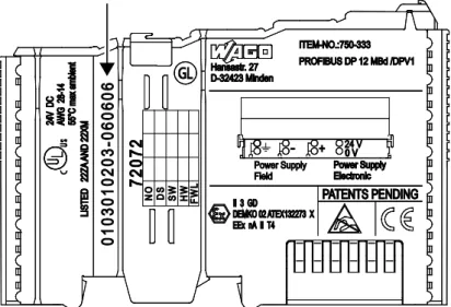
The serial number indicates the delivery status directly after production. This number is part of the labeling on the side of each component.
In addition, the serial number is printed on the cover cap of the configuration and programming interface of the fieldbus coupler/controller, so that it can also be read when installed.
Figure 2: Labeling on the Side of a Component (Example)
Manufacturing number 01 03 01 02 03 - B060606 Calendar week Year Software version Hardware version Firmware loader version Internal number
Figure 3: Example of a Manufacturing Number
The manufacturing number consists of the production week and year, the software version (if available), the hardware version of the component, the firmware loader (if available) and further internal information for WAGO Kontakttechnik GmbH & Co. KG.
Pos : 19.7 /Serie 750 (WAGO-I/ O-SYST EM)/ Syst embesc hrei bung/ Ger ät und Sys tem/Har dwar e-Adress e (M AC-ID) @ 7\ mod_1270708464299_21. doc x @ 54960 @ 2 @ 1
3.2
Hardware Address (MAC ID)
Each ETHERNET TCP/IP 2-port Controller has an internationally unambiguous physical address, referred to as the MAC-ID (Media Access Control Identity). As part of the labeling on the right side of this component, the MAC ID is printed in the block diagram of the fieldbus coupler/controller.
In addition, the MAC ID is located on the paper strip with two self-adhesive peel-off strips on the left side of the fieldbus coupler/controller.
750-871 ETHERNET TCP/IP 2-port Controller
Pos : 19.9 /Serie 750 (WAGO-I/ O-SYST EM)/ Syst embesc hrei bung/ Ger ät und Sys tem/Komponent en-Update-M atri x @ 3\ mod_1231757422359_21. doc x @ 25928 @ 2 @ 1
3.3
Component Update
For the case of an update of one component, the lateral marking on each component contains a prepared matrix.
This matrix makes columns available for altogether three updates to the entry of the current update data, like production order number (NO; starting from calendar week 13/2004), date stamp (DS), software version (SW), hardware version (HW) and the firmware loader version (FWL, if available).
Current version data for 1. Update 2. Update 3. Update
Production order no. NO only starting from Date stamp DS calendar week 13/2004 Software version SW
Hardware version HW
Firmware loader vers. FWL only for fieldbus couplers/controllers
If the update of a component took place, the current version data are registered into the columns of the matrix.
Additionally with the update of a fieldbus coupler or controller also the cover of the configuration and programming interface of the fieldbus coupler or controller is imprinted with the current production order number.
The original manufacturing information on the device's housing remains unchanged.
Pos : 19.10 / Serie 750 ( WAG O-I/ O-SYST EM)/Systembesc hrei bung/G erät und Syst em/ Lagerung, Kommissi onierung und Tr ansport @ 3\ mod_1225446600609_21. doc x @ 24897 @ 2 @ 1
3.4
Storage, Assembly and Transport
Whenever possible, the components are to be stored in their original packaging. Likewise, the original packaging provides optimal protection during transport. When assembling or repacking the components, the contacts must not be soiled or damaged. The components must be stored and transported in appropriate
containers/packaging. Thereby, the ESD information is to be regarded.
750-871 ETHERNET TCP/IP 2-port Controller
Pos : 19.12 / Serie 750 ( WAG O-I/ O-SYST EM)/Systembesc hrei bung/G erät und Syst em/ Aufbaurichtli nien und N or men @ 3\ mod_1231311929250_21. doc x @ 25820 @ 2 @ 1
3.5
Assembly Guidelines/Standards
DIN 60204 Electrical equipping of machines
DIN EN 50178 Equipping of high-voltage systems with electronic components (replacement for VDE 0160)
EN 60439 Low voltage switchgear assemblies
750-871 ETHERNET TCP/IP 2-port Controller
Pos : 19.14. 1 / Serie 750 ( WAG O-I/O- SYST EM)/Sys tembesc hrei bung/Vers orgung/ Spannungsvers orgung - Ü berschrif t 2 @ 3\ mod_1232950078953_21. doc x @ 26680 @ 2 @ 1
3.6
Power Supply
Pos : 19.14. 2 / Serie 750 ( WAG O-I/O- SYST EM)/Sys tembesc hrei bung/Vers orgung/ Potenti altrennung @ 3\mod_1232950094125_21.doc x @ 26732 @ 3 @ 1
3.6.1
Isolation
Within the fieldbus node, there are three electrically isolated potentials:
• Electrically isolated fieldbus interface via transformer
• Electronics of the fieldbus couplers/controllers and the I/O modules
(internal bus)
• All I/O modules have an electrical isolation between the electronics
(internal bus, logic) and the field electronics. Some digital and analog input modules have each channel electrically isolated, please see catalog.
Pos : 19.14. 3 / Serie 750 ( WAG O-I/O- SYST EM)/Sys tembesc hrei bung/Vers orgung/ Potenti altrennung - Bil d (Standar d + er weit ert er EC O) @ 3\ mod_1232950095187_21. doc x @ 26740 @ @ 1
Figure 4: Isolation for Fieldbus Couplers/Controllers (Example)
750-871 ETHERNET TCP/IP 2-port Controller
Pos : 19.14. 5 / Serie 750 ( WAG O-I/O- SYST EM)/Sys tembesc hrei bung/Vers orgung/ Syst emversorgung - Ü bersc hrift 3 @ 3\ mod_1232950096265_21.doc x @ 26748 @ 3 @ 1
3.6.2
System Supply
Pos : 19.14. 6 / Serie 750 ( WAG O-I/O- SYST EM)/Sys tembesc hrei bung/Vers orgung/ Syst emversorgung - Ans chl uss @ 3\ mod_1232950096796_21. doc x @ 26752 @ 4 @ 1
3.6.2.1 Connection
The WAGO-I/O-SYSTEM 750 requires a 24 V direct current system supply. The power supply is provided via the fieldbus coupler/controller and, if necessary, in addition via internal system supply modules 750-613. The power supply is reverse voltage protected.
Do not use an incorrect voltage/frequency!
The use of an incorrect supply voltage or frequency can cause severe damage to the components.
Pos : 19.14. 7 / Serie 750 ( WAG O-I/O- SYST EM)/Sys tembesc hrei bung/Vers orgung/ Syst emversorgung - Ans chl uss - Sys temvers orgung ( St andar d + er wei tert er ECO) @ 3\ mod_1232950104031_21. doc x @ 26776 @ @ 1
Figure 5: System Supply via Fieldbus Coupler/Controller (left) and via Internal System Supply Module (right)
Table 3: Legend for Figure “System Supply via Fieldbus Coupler/Controller (left) and via Internal System Supply Module (right)”
Position Description
1 System supply DC 24 V (-25 % … +30 %)
2 System supply 0 V
Pos : 19.14. 8 / Serie 750 ( WAG O-I/O- SYST EM)/Sys tembesc hrei bung/Vers orgung/ Syst emversorgung - Ans chl uss - Di e eing espeist e 24 V-Gleic hs pannung versorgt. .. @ 3\ mod_1232950097328_21. doc x @ 26756 @ @ 1
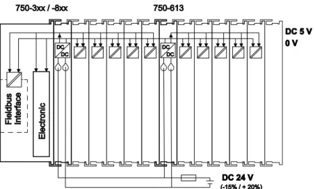
The fed DC 24 V supplies all internal system components, e.g. fieldbus
coupler/controller electronics, fieldbus interface and I/O modules via the internal bus (5 V system voltage). The 5 V system voltage is galvanically connected to the
750-871 ETHERNET TCP/IP 2-port Controller
Figure 6: System Voltage for Standard Couplers/Controllers and Extended ECO Couplers
Pos : 19.14. 10 / Seri e 750 ( WAGO-I /O-SYSTEM)/ Syst embes chr eibung/ Versorgung/Syst emvers orgung - Ansc hlus s - Hi nweis : Gl eichz. R üc ks et zen aller Vers orgungsmodul e @ 3\ mod_1232950097906_21. doc x @ 26760 @ @ 1
Only reset the system simultaneously for all supply modules!
Reset the system by simultaneously switching the system supply at all supply modules (fieldbus coupler/controller and potential supply module with bus power supply) off and on again.
Pos : 19.14. 11 / Seri e 750 ( WAGO-I /O-SYSTEM)/ Syst embes chr eibung/ Versorgung/Syst emvers orgung - Ausl egung @ 3\ mod_1232950104812_21. doc x @ 26780 @ 4 @ 1
3.6.2.2 Dimensioning
Recommendation
A stable power supply cannot always be assumed. Therefore, you should use regulated power supplies to ensure the quality of the supply voltage.
The supply capacity of the fieldbus coupler/controller or the internal system supply module can be taken from the technical data of the components. Table 4: Alignment
Internal current consumption*)
Current consumption via system voltage (5 V for electronics of I/O modules and fieldbus coupler/controller).
Total current for I/O modules*)
Available current for the I/O modules. Provided by the bus power supply unit. See fieldbus coupler/controller and internal system supply module
*) See current catalog, manuals, Internet
750-871 ETHERNET TCP/IP 2-port Controller
Pos : 19.14. 13 / Seri e 750 ( WAGO-I /O-SYSTEM)/ Syst embes chr eibung/ Versorgung/Beis piel: @ 3\ mod_1232630417843_21.doc x @ 26605 @ @ 1
Example:
Pos : 19.14. 14 / Seri e 750 ( WAGO-I /O-SYSTEM)/ Syst embes chr eibung/ Versorgung/Syst emvers orgung - Ausl egung - Beispi el 1 (Standar d) @ 3\ mod_1232950106875_21.doc x @ 26792 @ @ 1
Calculating the current consumption on the fieldbus coupler:
Internal current consumption of the coupler 350 mA at 5 V
Total current for I/O modules 1650 mA at 5 V
Sum I(5 V) total 2000 mA at 5 V
Pos : 19.14. 15 / Seri e 750 ( WAGO-I /O-SYSTEM)/ Syst embes chr eibung/ Versorgung/Syst emvers orgung - Ausl egung - Inter ne Stromaufnahme/ Summenstr om @ 3\ mod_1232950111375_21. doc x @ 26816 @ @ 1
The internal current consumption is indicated in the technical data for each bus terminal. In order to determine the total requirement, add together the values of all I/O modules in the node.
Please note the aggregate current for I/O modules. It may be necessary to supply potential!
When the sum of the internal current consumption for the I/O modules exceeds their aggregate current, you must use a supply module with bus power supply. Install it before the position where the permissible aggregate current would be exceeded.
Pos : 19.14. 16 / Seri e 750 ( WAGO-I /O-SYSTEM)/ Syst embes chr eibung/ Versorgung/Beis piel: @ 3\ mod_1232630417843_21.doc x @ 26605 @ @ 1
Example:
Pos : 19.14. 17 / Seri e 750 ( WAGO-I /O-SYSTEM)/ Syst embes chr eibung/ Versorgung/Syst emvers orgung - Ausl egung - Beispi el 2 (Standar d) @ 3\ mod_1232950109109_21.doc x @ 26804 @ @ 1
Calculating the total current on a standard fieldbus coupler/controller:
A node configuration with 20 relay modules (750-517) and 30 digital input modules (750-405) should be attached to a fieldbus coupler/controller:
Internal current consumptions 20 × 90 mA = 1800 mA at 5 V
+ 30 × 2 mA = 60 mA at 5 V
Sum of internal current consumptions 1860 mA at 5 V
However, the fieldbus coupler can only provide 1650 mA for the I/O modules. Consequently, an internal system supply module (750-613), e. g. in the middle of the node, should be added.
Pos : 19.14. 18 / Seri e 750 ( WAGO-I /O-SYSTEM)/ Syst embes chr eibung/ Versorgung/Syst emvers orgung - Ausl egung - Berec hnung Ei ngangsstrom @ 3\ mod_1232950109984_21.doc x @ 26808 @ @ 1
Recommendation
Utilize the smartDESIGNER feature WAGO ProServe® software to configure
fieldbus node assembly. You can test the configuration via the integrated plausibility check.
The maximum input current of the 24 V system supply is 500 mA. The exact
750-871 ETHERNET TCP/IP 2-port Controller Fieldbus coupler or controller
I(5 V) total = Sum of all the internal current consumption of the connected I/O modules + internal current consumption of the fieldbus coupler/controller
Internal system supply module
I(5 V) total = Sum of all the internal current consumption of the connected I/O modules at internal system supply module
Input current I(24 V) =
5 V
× I(5 V) total
24 V η
Pos : 19.14. 19 / Seri e 750 ( WAGO-I /O-SYSTEM)/ Syst embes chr eibung/ Versorgung/Syst emvers orgung - Ausl egung - n= 0, 87 (87% N etz teil wir kungsgrad bei 24 V) @ 3\ mod_1232950112718_21.doc x @ 26824 @ @ 1
η = 0.87
(87 % Efficiency of the power supply at nominal load 24 V)
Pos : 19.14. 20 / Seri e 750 ( WAGO-I /O-SYSTEM)/ Syst embes chr eibung/ Versorgung/Syst emvers orgung - Ausl egung - Hi nweis: Bei Test der Str omauf nahme Ausg äng e akti vi eren @ 3\ mod_1232950110750_21. doc x @ 26812 @ @ 1
Activate all outputs when testing the current consumption!
If the electrical consumption of a power supply point for the 24 V system supply exceeds 500 mA, then the cause may be an improperly dimensioned node or a defect.
During the test, you must activate all outputs.
750-871 ETHERNET TCP/IP 2-port Controller
Pos : 19.14. 22 / Seri e 750 ( WAGO-I /O-SYSTEM)/ Syst embes chr eibung/ Versorgung/F eldversorgung - Ü bersc hrift 3 @ 3\ mod_1232950080953_21.doc x @ 26688 @ 3 @ 1
3.6.3
Field Supply
Pos : 19.14. 23 / Seri e 750 ( WAGO-I /O-SYSTEM)/ Syst embes chr eibung/ Versorgung/F eldversorgung - Ans chl uss @ 3\ mod_1232950082031_21. doc x @ 26696 @ 4 @ 1
3.6.3.1 Connection
Sensors and actuators can be directly connected to the relevant channel of the I/O module in 1, 2, 3 or 4 conductor connection technology. The I/O module supplies power to the sensors and actuators. The input and output drivers of some I/O modules require the field side supply voltage.
Pos : 19.14. 24 / Seri e 750 ( WAGO-I /O-SYSTEM)/ Syst embes chr eibung/ Versorgung/F eldversorgung - Ans chl uss - Ei nspeis ung fel dsei tig (St andard + er weitert er ECO) @ 3\ mod_1232950087703_21. doc x @ 26712 @ @ 1
The fieldbus coupler/controller provides field side power (DC 24 V). In this case it is a passive power supply without protection equipment.
Pos : 19.14. 25 / Seri e 750 ( WAGO-I /O-SYSTEM)/ Syst embes chr eibung/ Versorgung/F eldversorgung - Ans chl uss - Pot entialgruppen mit Eins peisekl emme @ 3\ mod_1232950090437_21. doc x @ 26720 @ @ 1
Power supply modules with or without fuse holder and diagnostic capability are available for the power supply of other field potentials (DC 24 V, AC/DC 0 … 230 V, AC 120 V, AC 230 V). The power supply modules can also be used to set up various potential groups. The connections are connected in pairs to a power contact.
Pos : 19.14. 26 / Seri e 750 ( WAGO-I /O-SYSTEM)/ Syst embes chr eibung/ Versorgung/F eldversorgung - Ans chl uss - Bild: F el dvers orgung (St andard + er weit erter ECO) @ 3\ mod_1232950085156_21.doc x @ 26704 @ @ 1
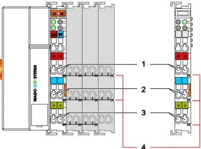
Figure 7: Field Supply for Standard Couplers/Controllers and Extended ECO Couplers
Pos : 19.14. 27 / Seri e 750 ( WAGO-I /O-SYSTEM)/ Syst embes chr eibung/ Versorgung/F eldversorgung - Leg ende z u Abbildung "F el dvers orgung für St andard-F eldbus k/F el dvers orgung - Legende zu Abbil dung "F eldversorgung f ür St andard-Fel dbus k/-contr oller u er w EC O-F" @ 16\ mod_1375693993330_21. doc x @ 127730 @ @ 1
Table 5: Legend for Figure “Field Supply for Standard Couplers/Controllers and Extended ECO Couplers”
Field supply
1 24 V (-15 % / +20 %) 2 0 V
3 Optional ground potential
Power jumper contacts
4 Potential distribution to adjacent I/O modules
Pos : 19.14. 28 / Seri e 750 ( WAGO-I /O-SYSTEM)/ Syst embes chr eibung/ Versorgung/F eldversorgung - Ans chl uss - Weiterl eit ung Vers orgungsspg., Strombel ast ung 10 A, neue Eins peisekl emme @ 8\ mod_1279805441785_21.doc x @ 60845 @ @ 1
750-871 ETHERNET TCP/IP 2-port Controller
By inserting an additional power supply module, the field supply via the power contacts is disrupted. From there a new power supply occurs which may also contain a new voltage potential.
Pos : 19.14. 29 / Seri e 750 ( WAGO-I /O-SYSTEM)/ Syst embes chr eibung/ Versorgung/F eldversorgung - Ans chl uss - 2 Hi nweise: Pot ential neu ei ns peis en + Dis tanz kl emme @ 3\ mod_1232950091343_21.doc x @ 26724 @ @ 1
Re-establish the ground connection when the connection to the power jumper contacts is disrupted!
Some I/O modules have no or very few power contacts (depending on the I/O function). Due to this, the passing through of the relevant potential is disrupted. If you require a field supply via power jumper contacts for subsequent I/O modules, then you have to use a power supply module.
Note the data sheets of the I/O modules.
Use a spacer module when setting up a node with different potentials!
In the case of a node setup with different potentials, e.g. the alteration from DC 24 V to AC 230 V, you should use a spacer module. The optical separation of the potentials acts as a warning to heed caution in the case of wiring and
maintenance works. Thus, you can prevent the results of wiring errors.
750-871 ETHERNET TCP/IP 2-port Controller
Pos : 19.14. 31 / Seri e 750 ( WAGO-I /O-SYSTEM)/ Syst embes chr eibung/ Versorgung/F eldversorgung - Absic herung @ 3\ mod_1232950081500_21.doc x @ 26692 @ 4 @ 1
3.6.3.2 Fusing
Internal fusing of the field supply is possible for various field voltages via an appropriate power supply module.
Table 6: Power Supply Modules
Order No. Field Voltage
750-601 24 V DC, Supply/Fuse 750-609 230 V AC, Supply/Fuse 750-615 120 V AC, Supply/Fuse 750-617 24 V AC, Supply/Fuse 750-610 24 V DC, Supply/Fuse/Diagnosis 750-611 230 V AC, Supply/Fuse/Diagnosis 750-606 Supply Module 24 V DC, 1,0 A, Ex i
750-625/000-001 Supply Module 24 V DC, 1,0 A, Ex i (without diagnostics)
Figure 8: Supply Module with Fuse Carrier (Example 750-610)
Observe the maximum power dissipation and, if required, UL requirements!
In the case of power supply modules with fuse holders, you must only use fuses with a maximum dissipation of 1.6 W (IEC 127).
For UL approved systems only use UL approved fuses.
750-871 ETHERNET TCP/IP 2-port Controller
Figure 9: Removing the Fuse Carrier
Lifting the cover to the side opens the fuse carrier.
Figure 10: Opening the Fuse Carrier
Figure 11: Changing the Fuse
750-871 ETHERNET TCP/IP 2-port Controller Alternatively, fusing can be done externally. The fuse modules of the WAGO series 281 and 282 are suitable for this purpose.
Figure 12: Fuse Modules for Automotive Fuses, Series 282
Figure 13: Fuse Modules for Automotive Fuses, Series 2006
750-871 ETHERNET TCP/IP 2-port Controller
Pos : 19.14. 33 / Seri e 750 ( WAGO-I /O-SYSTEM)/ Syst embes chr eibung/ Versorgung/Ergänz ende Eins peisungs vors chrift en (Standar d) @ 3\ mod_1232950080218_21.doc x @ 26684 @ 3 @ 1
3.6.4
Supplementary Power Supply Regulations
The WAGO-I/O-SYSTEM 750 can also be used in shipbuilding or offshore and onshore areas of work (e. g. working platforms, loading plants). This is
demonstrated by complying with the standards of influential classification companies such as Germanischer Lloyd and Lloyds Register.
Filter modules for 24 V supply are required for the certified operation of the system.
Table 7: Filter Modules for 24 V Supply
Order No. Name Description
750-626 Supply Filter Filter module for system supply and field supply
(24 V, 0 V), i. e. for fieldbus coupler/controller and bus power supply (750-613)
750-624 Supply Filter Filter module for the 24 V field supply
(750-602, 750-601, 750-610)
Therefore, the following power supply concept must be absolutely complied with.
Figure 16: Power Supply Concept
Use a supply module for equipotential bonding!
Use an additional 750-601/ 602/ 610 Supply Module behind the 750-626 Filter Module if you want to use the lower power jumper contact for equipotential bonding, e.g., between shielded connections and require an additional tap for this potential.
750-871 ETHERNET TCP/IP 2-port Controller
Pos : 19.14. 35 / Seri e 750 ( WAGO-I /O-SYSTEM)/ Syst embes chr eibung/ Versorgung/Vers orgungs beis piel - Übersc hrift + Hinweis @ 3\ mod_1232949833531_21. doc x @ 26670 @ 3 @ 1
3.6.5
Supply Example
Suppl Sggggggggggggggggg
The system supply and the field supply shall be separated!
You should separate the system supply and the field supply in order to ensure bus operation in the event of a short-circuit on the actuator side.
Pos : 19.14. 36 / Seri e 750 ( WAGO-I /O-SYSTEM)/ Syst embes chr eibung/ Versorgung/Vers orgungs beis piel - Bil d (Standar d) @ 3\ mod_1232950114015_21.doc x @ 26832 @ @ 1
Figure 17: Supply Example for Standard Couplers/Controllers
750-871 ETHERNET TCP/IP 2-port Controller
Table 8: Legend for Figure “Supply Example for Fieldbus Coupler/Controller”
Pos. Description
1 Power Supply on coupler via external Supply Module
2 Power Supply with optional ground
3 Internal System Supply Module
4 Separation module recommended
5 Supply Module passive
6 Supply Module with fuse carrier/diagnostics
750-871 ETHERNET TCP/IP 2-port Controller
Pos : 19.14. 39 / Seri e 750 ( WAGO-I /O-SYSTEM)/ Syst embes chr eibung/ Versorgung/Netzger ät e @ 3\ mod_1232950093484_21. doc x @ 26728 @ 3 @ 1
3.6.6
Power Supply Unit
The WAGO-I/O-SYSTEM 750 requires a 24 VDC voltage (system supply).
Recommendation
A stable power supply cannot always be assumed everywhere. Therefore, you should use regulated power supplies to ensure the quality of the supply voltage (see also table “WAGO power supply units”).
For brief voltage dips, a buffer (200 µF per 1 A load current) must be provided.
Power failure time not acc. IEC 61131-2!
Note that the power failure time of 10 ms acc. IEC 61131-2 is not maintained in a maximum configuration.
The power demand must be determined individually depending on the entry point of the field supply. All loads through field devices and I/O modules must be taken into account. The field supply also impacts the I/O modules because the input and output drivers of some I/O modules require the voltage of the field supply.
System and field supply must be isolated!
The system supply and field supply must be isolated to ensure bus operation in the event of short circuits on the actuator side.
Table 9: WAGO Power Supply Units (Selection)
WAGO Power Supply Unit
Description
787-612 Primary switched mode;
DC 24 V; 2,5 A Input nominal voltage AC 230 V
787-622 Primary switched mode;
DC 24 V; 5 A Input nominal voltage AC 230 V
787-632 Primary switched mode;
DC 24 V; 10 A Input nominal voltage AC 230/115 V Rail-mounted modules with universal mounting carrier
288-809 AC 115 V/DC 24 V; 0,5 A
288-810 AC 230 V/DC 24 V; 0,5 A
288-812 AC 230 V/DC 24 V; 2 A
750-871 ETHERNET TCP/IP 2-port Controller
Pos : 19.14. 41 / Seri e 750 ( WAGO-I /O-SYSTEM)/ Syst embes chr eibung/ Versorgung/Er dung @ 3\ mod_1231246555687_21. doc x @ 25802 @ 23443 @ 1
3.7
Grounding
3.7.1
Grounding the DIN Rail
3.7.1.1 Framework AssemblyWhen setting up the framework, the carrier rail must be screwed together with the electrically conducting cabinet or housing frame. The framework or the housing must be grounded. The electrical connection is established via the screw. Thus, the carrier rail is grounded.
Ensure sufficient grounding is provided!
You must take care to ensure the flawless electrical connection between the carrier rail and the frame or housing in order to guarantee sufficient grounding.
3.7.1.2 Insulated Assembly
Insulated assembly has been achieved when there is constructively no direct ohmic contact between the cabinet frame or machine parts and the carrier rail. Here, the earth ground must be set up via an electrical conductor in accordance with valid national safety regulations.
Recommendation
The optimal setup is a metallic assembly plate with grounding connection which is electrically conductive linked to the carrier rail.
The separate grounding of the carrier rail can be easily set up with the aid of the WAGO ground wire terminals.
Table 10: WAGO Ground Wire Terminals
Order No. Description
283-609 1-conductor ground (earth) terminal block make an automatic contact
to the carrier rail; conductor cross section: 0.2 mm² … 16 mm2
750-871 ETHERNET TCP/IP 2-port Controller
3.7.2
Grounding Function
The grounding function increases the resistance against electro-magnetic
interferences. Some components in the I/O system have a carrier rail contact that dissipates electro-magnetic interferences to the carrier rail.
Figure 18: Carrier Rail Contact (Example)
Ensure sufficient grounding is provided!
You must take care to ensure the direct electrical connection between the carrier rail contact and the carrier rail.
The carrier rail must be grounded.
For information on carrier rail properties, see section “Mounting” > … > “Carrier Rail Properties”.
The bottom CAGECLAMP®connectors of the supply modules enable optional
connection of a field-side functional ground. This potential is made available to the I/O module arranged on the right through the spring-loaded contact of the three power contacts. Some I/O modules are equipped with a knife-edge contact that taps this potential. This forms a potential group with regard to functional ground with the I/O module arranged on the left.
750-871 ETHERNET TCP/IP 2-port Controller
Pos : 19.14. 43 / Seri e 750 ( WAGO-I /O-SYSTEM)/ Syst embes chr eibung/ Versorgung/Schir mung @ 3\ mod_1231251994828_21. doc x @ 25813 @ 23333 @ 1
3.8
Shielding
3.8.1
General
Use of shielded cables reduces electromagnetic interference and thus increases signal quality. Measurement errors, data transmission errors and interference due to excessive voltage can be prevented.
Connect the cable shield to the ground potential!
Integrated shielding is mandatory to meet the technical specifications in regards to measuring accuracy. Connect the cable shield and ground potential at the inlet to the cabinet or housing. This allows induced interference to dissipate and to be kept away from devices in the cabinet or housing.
Improve shielding performance by placing the shield over a large area!
Higher shielding performance is achieved via low-impedance connection between shield and ground. For this purpose, connect the shield over a large surface area, e.g., WAGO shield connecting system. This is especially recommended for large-scale systems where equalizing current or high impulse-type currents caused by atmospheric discharge may occur.
Keep data and signal lines away from sources of interference!
Route data and signal lines separately from all high voltage cables and other sources of high electromagnetic emission (e.g., frequency converter or drives).
3.8.2
Bus Cables
The shielding of the bus line is described in the respective configuration guidelines and standards of the bus system.
750-871 ETHERNET TCP/IP 2-port Controller
3.8.3
Signal Lines
I/O modules for analog signals and some interface I/O modules are equipped with shield clamps.
Use shielded signal lines!
Only use shielded signal lines for analog signals and I/O modules which are equipped with shield clamps. Only then can you ensure that the accuracy and interference immunity specified for the respective I/O module can be achieved even in the presence of interference acting on the signal cable.
3.8.4
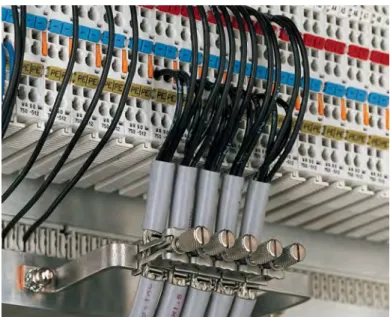
WAGO Shield Connecting System
The WAGO shield connecting system consists of shield clamping saddles, busbars and various mounting carriers. These components can be used to achieve many different configurations.
Figure 19: Examples of the WAGO Shield Connecting System