Pavement Design Supplement
Supplement to ‘Part 2: Pavement Structural Design’ of
the Austroads Guide to Pavement Technology
Foreword
The Queensland Department of Transport and Main Roads (TMR) adopts the fundamental pavement design principles in Part 2: Pavement Structural Design of the Austroads Guide to Pavement
Technology (Austroads, 2012), hereafter referred to as AGPT02.
TMR has published this Pavement Design Supplement (“this supplement”), for use in TMR projects, to complement the design guidance provided by Austroads, such as for Queensland’s local materials, environment, loadings and pavement performance. Therefore, this supplement generally does not repeat the guidance already provided in AGPT02, and pavement designers completing designs for TMR works should use this supplement in conjunction with AGPT02, as well as any other project-specific requirements.
This supplement replaces the Pavement Design Manual (Main Roads, 2009).
For ease of reference, section numbers in this supplement align with the applicable section numbers in AGPT02. References to section numbers, tables, figures, equations and appendices are to be read as references to both this supplement and AGPT02. Where additional sections, tables, figures, equations and appendices are included in this supplement, these are numbered with a prefix of Q. This supplement is not a prescriptive standard, rather it is intended to be a guide for professional, trained, experienced and knowledgeable pavement designers who:
work within the confines of government policies, guidelines and road network requirements are aware of, assess and apply risk management and budgetary constraints to the road
system as a whole and its various components
apply engineering principles and data to a design, construction or production activity
take into account local area or project-specific issues, including when the typical assumptions and standards in this supplement are being considered, and
optimise initial designs and in-service treatments to suit budget and whole-of-life cost issues. As this supplement is not a prescriptive standard, reference to it in contract documents will typically require project-specific requirements appropriate for the contract to be included in a pavement design brief. A pavement design brief is essential for projects where the designer is external to TMR,
particularly where the contract is a type where the designer is employed or engaged by a third party such as a construction contractor or developer. A more detailed brief is likely required for these types of contracts, as compared to an RCC-style (AS2124) contract. Further guidance on developing project design briefs is included in Section 1.2.
Due to differences between design inputs and whole-of-life actualities (e.g. traffic growth, enforcement of and changes to legislation relating to heavy vehicle loading, variability in construction, accuracy of design models, environmental considerations and ongoing maintenance and rehabilitation) the
guidance contained in AGPT02 and this supplement can provide only an indication of future pavement performance. Specifically, the guidance provided for typical design assumptions and standards is
whole network within the context of budgetary constraints and the comparatively large geographical area of Queensland with a relatively low population density
reducing high cost maintenance interventions and associated user disruptions on highly trafficked urban roads remains a priority
vehicle load intensities are increasing, causing increased vertical loading and associated increases in horizontal shear loading
expectations about safety requirements, and
delivering value for money, including working within the constraints of limited initial budgets. Alternatives and exceptions to AGPT02 and this supplement’s typical design assumptions and standards may be necessary for the designer’s project-specific engineering design. In making these professional engineering decisions, designers are implicitly evaluating the engineering risks and benefits to the project based on application of the pertinent engineering technology. Professional engineers will recognise that there may be compounding and interconnected risks and/or opportunities when multiple changes to typical values are applied in determining a design solution.
Where innovations are being considered, designers and project managers should refer to Engineering Innovation within TMR (TMR, 2013a).
Contents
1 Introduction ...1
1.1 Scope of the guide... 1
1.2 Project scope and background data requirements for design ... 2
1.2.1 Investigation and design proposal...2
2 Pavement design systems...2
2.1 Common pavement types... 2
2.2.1 General...2
2.2.2 Granular pavements with sprayed seal surfacings ...5
2.2.3 Cemented granular bases with sprayed seal surfacings...5
2.2.4 Granular pavements with thin asphalt surfacings ...5
2.2.5 Asphalt over granular pavements...6
2.2.6 Flexible composite, deep strength and full depth asphalt pavements ...7
2.2.7 Concrete pavements ...9
Q2.2.8 Asphalt over cementitiously stabilised granular pavement ...9
2.3 Overview of pavement design systems ... 11
2.3.1 Input variables ...11
Q2.4Shoulders with a lower structural standard... 11
3. Construction and maintenance considerations ...13
3.1 General ... 13
3.2 Extent and type of drainage... 13
3.2.2 Drainage of pavement materials ...15
3.2.3 Use of a drainage blanket ...15
3.6 Use of stabilisation... 15
3.7 Pavement layering considerations... 15
3.8 Use of strain alleviating membrane interlayers... 16
3.9 Environmental and safety constraints... 16
3.11 Construction under traffic... 17
3.14 Improved subgrades ... 17
3.14.1 Soft subgrades ...17
3.14.2 Improved layers under bound layers ...20
3.15 Surfacing type... 21
3.15.1 Sprayed seals...21
3.15.3 Open-graded asphalt...21
Q3.17 Settlement ... 21
Q3.18 Pavement jointing considerations ... 21
Q3.19 Thickness of bituminous seals ... 21
Q3.20 Temporary pavements in high traffic situations ... 21
5.3.5 Moisture changes during service life ...25
5.6 Laboratory determination of subgrade CBR and elastic parameters ... 28
5.6.1 Determination of density for laboratory testing...28
5.6.2 Determination of moisture conditions for laboratory testing ...29
5.7 Adoption of presumptive CBR values... 29
6 Pavement Materials ...30
6.2 Unbound granular materials ... 30
6.2.1 Introduction...30
6.2.3 Determination of modulus of unbound granular materials ...31
6.3 Modified granular materials ... 32
6.4 Cemented materials... 33
6.4.1 Introduction...33
6.4.3 Determination of design modulus...33
6.5 Asphalt... 34
6.5.3 Determination of asphalt design modulus and Poisson’s ratio ...34
6.5.4 Factors affecting asphalt fatigue life...36
6.5.7 Permanent deformation of asphalt ...36
6.5.8 Recycled asphalt ...37
6.6 Concrete ... 37
6.6.3 Base concrete...37
Q6.7Foamed bitumen stabilised materials ... 37
7 Design Traffic ...38
7.4 Procedure for determining total heavy vehicle axle groups... 38
7.4.2 Selection of design period ...38
7.4.4 Initial Daily Heavy Vehicles in the Design Lane ...38
7.4.5 Cumulative traffic volumes ...39
7.5 Estimation of Traffic Load Distribution (TLD)... 39
8 Design of flexible pavements ...39
8.1 General ... 39
8.2 Mechanistic procedure... 40
8.2.2 Procedure for elastic characterisation of selected subgrade materials...40
8.3 Empirical design of granular pavements with thin bituminous surfacing... 40
8.3.1 Determination of basic thickness...40
9 Design of new rigid pavements...41
9.2 Pavement types ... 41
9.2.2 Subbase types...41
9.2.3 Wearing surface ...41
9.4 Base thickness design ... 41
12.4 Environment... 42
12.4.2 Moisture...42
12.6 Pavement materials ... 43
12.6.1 Unbound granular materials ...43
12.6.2 Cemented materials ...43
13 References...44
Tables
Table Q2.1 – Guide to the selection of pavement types based on traffic (ESA)... 4
Table Q2.2 – Typical structure of granular pavement with sprayed seal surfacing (SG and SG(HD))... 5
Table Q2.3 – Typical structure of cementitiously stabilised granular base with sprayed seal ... 5
Table Q2.4 – Typical structure of granular pavement with thin asphalt surfacing (AG(B))... 6
Table Q2.5 – Typical structure of asphalt over granular pavement (AG(A))... 6
Table Q2.6 – Typical structure of flexible composite pavement (FC) for heavy-duty applications ... 7
Table Q2.7 – Typical structure of deep strength asphalt pavement (DSA) for heavy-duty applications. 8 Table Q2.8 – Typical structure of full depth asphalt pavement (FDA) for heavy-duty applications ... 9
Table Q2.9 – Typical structure of concrete pavement for heavy-duty applications ... 9
Table Q2.10 –Typical structure of asphalt over cementitiously stabilised granular pavement (ASt(A))10 Table Q2.11 – Typical structure of asphalt surfacing over cementitiously stabilised granular base pavement (ASt(B))... 11
Table Q2.12 – Typical project reliability levels ... 11
Table Q3.1 – Typical minimum cover to provide a stable construction platform... 17
Table Q3.2 – Minimum thickness of coarse granular or rock fill required for the adoption of a presumptive design CBR of 3% ... 18
Table Q5.1 – Guide to Moisture Conditions for Laboratory CBR Testing ... 29
Table Q6.1 – Typical application of standard materials (MRTS05 Type) in sealed unbound granular pavements ... 31
Table Q6.2 – Presumptive values for elastic characterisation of unbound granular base materials under thin bituminous surfacings... 32
Table Q6.3 – Presumptive values for elastic characterisation of unbound granular materials used as subbase/improved layer (working platform) under bound pavement layers ... 32
Table Q6.4 – Presumptive values for elastic characterisation of standard cemented materials ... 34
Table Q6.5 – Presumptive values for elastic characterisation of asphalt mixes at a WMAPT of 32ºC 35 Table Q6.6 – Presumptive heavy vehicle operating speeds ... 36
Figures
Figure Q3.1 – Example of mechanistic model for a soft subgrade treatment where the CBR of the in
situ material at the design conditions is less than 3%... 19
Figure Q4.1 – Australian Climatic Zones (www.bom.gov.au) ... 22
Figure Q4.2 – Australian seasonal rainfall zones (www.bom.gov.au) ... 23
Figure Q4.3 – Median Annual Isohyets for Queensland ... 24
Figure Q5.1 – Typical Cover Thickness Over Highly Expansive Material for Flexible Pavements (thickness includes the pavement) (VicRoads, 2010) ... 27
1 Introduction
1.1 Scope of the guide
This supplement is for the design of pavements that are within the scope of AGPT02. Limitations of AGPT02 in terms of its scope also apply to this supplement.
Pavements are assumed to be constructed to TMR quality requirements and standards.
This supplement and AGPT02 are part of a suite of technical documents which are relevant to the design and construction of pavements on TMR projects. Pavement designers and project managers are referred to other components of the suite which include the Austroads Guide to Pavement Technology (Parts 1 to 10) and the following TMR documents:
Specifications and Technical Standards Manual Pavement Rehabilitation Manual
Road Planning and Design Manual Materials Testing Manual
Road Drainage Manual
Road Traffic Noise Management: Code of Practice Skid Resistance Management Plan
Standard Drawings Roads Manual Asset Maintenance Guidelines Busway Planning and Design Manual
Engineering Notes, Policy Statements and Technical Notes Supplementary specifications and test methods
Risk Management Framework Guide to Risk Management
Guidelines for Strategic Road Network Planning
This supplement and AGPT02 do not specifically address the selection of pavement surfacings. In some cases, typical surfacings have been included to illustrate typical design outcomes. For project-specific selection, designers and project managers are referred to:
Part 3: Pavement Surfacings of the Austroads Guide to Pavement Technology (Austroads, 2009)
1.2 Project scope and background data requirements for design
1.2.1 Investigation and design proposal
For TMR projects, the proposal (often referred to as the pavement design brief) details the required outcomes of pavement design including:
assumptions regarding design inputs and level of acceptable risk project scope requirements listed in Table 1.1, and
method of reporting alternatives and exceptions (such as departures from the “typical” assumptions, methodology and standards in AGPT02 and this supplement) for TMR approval/acceptance, including:
i) reasons for the departure
ii) requirements for implementation (for example, modifications and/or additions to standard specifications)
iii) estimated cost savings or additional costs, and
iv) anticipated and/or potential impacts, including those on road users, serviceability, durability, whole-of-life performance, construction program, functional performance, maintenance requirements and safety.
Designers are expected to seek clarification from TMR regarding any aspects of the design requirements that are unclear or missing from the design brief.
2 Pavement design systems
2.1 Common pavement types
2.2.1 General
The choice of pavement type requires consideration of project-specific factors which may include: horizontal shear stresses on grades, curves and intersections (for example, granular
pavements with sprayed seal surfacing may not be suitable in some locations; and, for granular pavements with thin asphalt surfacings, it may be necessary to increase the thickness of asphalt in these areas)
likely in-service moisture conditions may limit the suitability of unbound granular materials heavy vehicle loads and/or pavement contact stresses higher than those used in the
development of the current pavement design models and technical standards availability and adequacy of materials and costs of transporting materials
adoption of standards higher than the minimums in the technical standards (e.g. when the standard of available materials is well in excess of the technical standards) may reduce the performance risk for some pavement types
changes to the road network during the design period specific functional requirements (e.g. safety, noise)
current and future traffic characteristics including anticipated changes to vehicle mass limits and tyre pressures during the design period
subgrade settlement and/or water-induced volume change which may impact on pavements with stabilised or rigid layers
whole-of-life costs which may include both direct and indirect costs such as structural
interventions, maintenance, rehabilitation, raising drainage structures, increasing clearances, raising safety barriers, providing temporary access, maintaining alternative routes, delays and disruptions to road users
sustainability requirements such as local laws, policies and regulations current and future budget considerations, and
local environmental conditions.
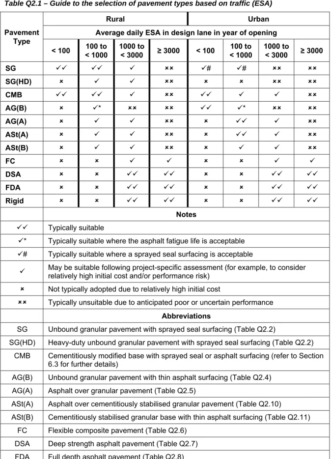
A guide to the selection of pavement types for TMR projects based on traffic loading is provided in Table Q2.1. This guide is intended to be used in conjunction with local practice and experience, and with the consideration of project-specific factors. For busway pavements, reference should also be made to the TMR Busway Planning and Design Manual.
Table Q2.1 – Guide to the selection of pavement types based on traffic (ESA)
Rural Urban Average daily ESA in design lane in year of opening
Pavement Type < 100 < 1000 100 to 1000 to < 3000 ≥ 3000 < 100 < 1000 100 to 1000 to < 3000 ≥ 3000 SG # # SG(HD) CMB AG(B) * * AG(A) ASt(A) ASt(B) FC DSA FDA Rigid Notes Typically suitable
* Typically suitable where the asphalt fatigue life is acceptable
# Typically suitable where a sprayed seal surfacing is acceptable
May be suitable following project-specific assessment (for example, to consider relatively high initial cost and/or performance risk) Not typically adopted due to relatively high initial cost
Typically unsuitable due to anticipated poor or uncertain performance
Abbreviations
SG Unbound granular pavement with sprayed seal surfacing (Table Q2.2)
SG(HD) Heavy-duty unbound granular pavement with sprayed seal surfacing (Table Q2.2) CMB Cementitiously modified base with sprayed seal or asphalt surfacing (refer to Section
6.3 for further details)
AG(B) Unbound granular pavement with thin asphalt surfacing (Table Q2.4) AG(A) Asphalt over granular pavement (Table Q2.5)
ASt(A) Asphalt over cementitiously stabilised granular pavement (Table Q2.10)
ASt(B) Cementitiously stabilised granular base with thin asphalt surfacing (Table Q2.11) FC Flexible composite pavement (Table Q2.6)
2.2.2 Granular pavements with sprayed seal surfacings
The typical structure of a granular pavement with a sprayed seal surfacing (SG and SG(HD)) is as shown in Table Q2.2.
Table Q2.2 – Typical structure of granular pavement with sprayed seal surfacing (SG and SG(HD))
Course Description (typical)
Surfacing1 Prime plus sprayed seal
Base and subbase Unbound granular material selected using Table Q6.1. Thicknesses are typically determined from Figure 8.4 or Figure 12.2. Notes:
1. Refer to Appendix A of AP-T236/13 (Austroads, 2013a) for guidance on specific treatment selection.
2.2.3 Cemented granular bases with sprayed seal surfacings
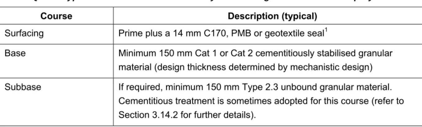
Pavements comprised of a cemented granular base with sprayed seal surfacing are at times adopted by TMR for floodways in remote areas where more resilient concrete pavements are determined to be uneconomical on a whole-of-life basis. Due to the significant maintenance/performance issues
associated with this pavement type, it should only be adopted after a rigorous pavement selection process has been undertaken that compares it to other alternatives. The typical structure of such a pavement is as shown in Table Q2.3.
Table Q2.3 – Typical structure of cementitiously stabilised granular base with sprayed seal
Course Description (typical)
Surfacing Prime plus a 14 mm C170, PMB or geotextile seal1
Base Minimum 150 mm Cat 1 or Cat 2 cementitiously stabilised granular material (design thickness determined by mechanistic design) Subbase If required, minimum 150 mm Type 2.3 unbound granular material.
Cementitious treatment is sometimes adopted for this course (refer to Section 3.14.2 for further details).
Notes:
1. Where improved resistance to reflective cracking is required, a SAM (PMB) or geotextile seal should be considered.
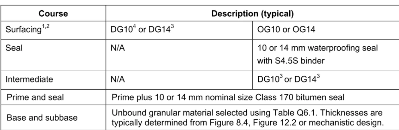
2.2.4 Granular pavements with thin asphalt surfacings
The typical structure of a granular pavement with thin asphalt surfacing (AG(B)) is as shown in Table Q2.4.
Table Q2.4 – Typical structure of granular pavement with thin asphalt surfacing (AG(B))
Course Description (typical)
Surfacing1,2 DG104 or DG143 OG10 or OG14
Seal N/A 10 or 14 mm waterproofing seal
with S4.5S binder
Intermediate N/A DG103 or DG143
Prime and seal Prime plus 10 or 14 mm nominal size Class 170 bitumen seal
Base and subbase Unbound granular material selected using Table Q6.1. Thicknesses are typically determined from Figure 8.4, Figure 12.2 or mechanistic design. Notes:
1. SMA may also be considered, subject to a project-specific assessment of its suitability. 2. Refer to Table Q6.7 for guidance on the selection of binder type in the asphalt layers. 3. The fatigue life of the asphalt should be assessed using mechanistic design.
4. Refer to Section 8.2.5 for guidance on the design of asphalt surfacings less than 40 mm thick. DG10 is typically limited to locations with design traffic less than 100 ESA/day at opening when C320 binder is used and 300 ESA/day at opening when A5S binder is used.
2.2.5 Asphalt over granular pavements
The typical structure of an asphalt over granular pavement (AG(A)) is as shown in Table Q2.5. Table Q2.5 – Typical structure of asphalt over granular pavement (AG(A))
Course Description (typical)
Surfacing1,2 DG14 OG10 or OG14
Seal3 10 or 14 mm waterproofing seal with S4.5S binder
Intermediate2 N/A DG14
Base2 DG14 or DG20 are typically adopted with either C320 or C600 binder. DG28 may be suitable in some situations but carries greater risk in relation to segregation. Thickness is determined by mechanistic design. Prime and seal4 Prime plus 10 or 14 mm nominal size Class 170 bitumen seal
Subbase Minimum 150 mm Type 2.3 unbound granular material. Cementitious treatment is sometimes adopted for this course (refer to Section 3.14.2 for further details).
Notes:
1. SMA may also be considered, subject to a project-specific assessment of its suitability. 2. Refer to Table Q6.7 for further guidance on the selection of binder type in the asphalt layers. 3. Refer to Section 3.7 for further guidance on the inclusion of the waterproofing seal.
2.2.6 Flexible composite, deep strength and full depth asphalt pavements
These pavements are typically heavy-duty pavements which incorporate heavy-duty asphalt. Typical structures of flexible composite (FC), deep strength asphalt (DSA) and full depth asphalt (FDA) pavements used in heavy-duty applications are as shown in Tables Q2.6, Q2.7 and Q2.8. TMR has limited experience with the use of flexible composite pavements.
Cracking of cemented materials, and subsequent reflection into overlying asphalt layers, should be anticipated in deep strength asphalt pavements.
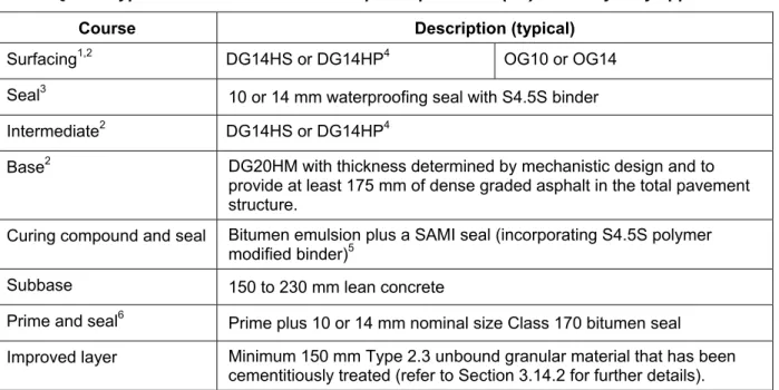
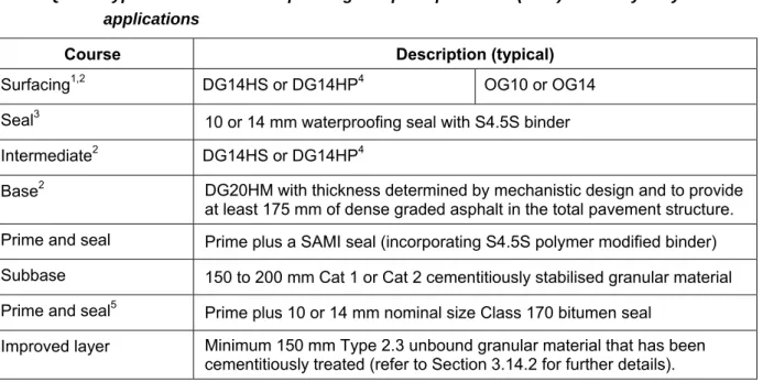
Table Q2.6 – Typical structure of flexible composite pavement (FC) for heavy-duty applications
Course Description (typical)
Surfacing1,2 DG14HS or DG14HP4 OG10 or OG14
Seal3 10 or 14 mm waterproofing seal with S4.5S binder Intermediate2 DG14HS or DG14HP4
Base2 DG20HM with thickness determined by mechanistic design and to provide at least 175 mm of dense graded asphalt in the total pavement structure.
Curing compound and seal Bitumen emulsion plus a SAMI seal (incorporating S4.5S polymer modified binder)5
Subbase 150 to 230 mm lean concrete
Prime and seal6 Prime plus 10 or 14 mm nominal size Class 170 bitumen seal Improved layer Minimum 150 mm Type 2.3 unbound granular material that has been
cementitiously treated (refer to Section 3.14.2 for further details). Notes:
1. SMA may also be considered, subject to a project-specific assessment of its suitability. 2. Refer to Table Q6.7 for further guidance on the selection of binder type in the asphalt layers. 3. Refer to Section 3.7 for further guidance on the inclusion of the waterproofing seal.
4. DG14HP is typically only adopted in free flowing traffic conditions (e.g. it may not be suitable for use at the approach to signalised intersections).
5. The SAMI seal can be substituted with a 7 mm Class 170 bitumen seal where an increased risk of future reflective cracking is accepted.
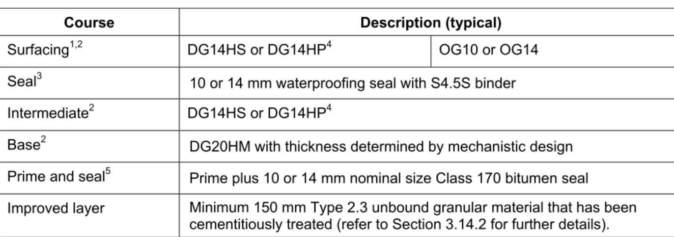
Table Q2.7 – Typical structure of deep strength asphalt pavement (DSA) for heavy-duty applications
Course Description (typical)
Surfacing1,2 DG14HS or DG14HP4 OG10 or OG14
Seal3 10 or 14 mm waterproofing seal with S4.5S binder Intermediate2 DG14HS or DG14HP4
Base2 DG20HM with thickness determined by mechanistic design and to provide at least 175 mm of dense graded asphalt in the total pavement structure. Prime and seal Prime plus a SAMI seal (incorporating S4.5S polymer modified binder) Subbase 150 to 200 mm Cat 1 or Cat 2 cementitiously stabilised granular material Prime and seal5 Prime plus 10 or 14 mm nominal size Class 170 bitumen seal
Improved layer Minimum 150 mm Type 2.3 unbound granular material that has been cementitiously treated (refer to Section 3.14.2 for further details). Notes:
1. SMA may also be considered, subject to a project-specific assessment of its suitability. 2. Refer to Table Q6.7 for further guidance on the selection of binder type in the asphalt layers. 3. Refer to Section 3.7 for further guidance on the inclusion of the waterproofing seal.
4. DG14HP is typically only adopted in free flowing traffic conditions (e.g. it may not be suitable for use at the approach to signalised intersections).
Table Q2.8 – Typical structure of full depth asphalt pavement (FDA) for heavy-duty applications
Course Description (typical)
Surfacing1,2 DG14HS or DG14HP4 OG10 or OG14
Seal3 10 or 14 mm waterproofing seal with S4.5S binder Intermediate2 DG14HS or DG14HP4
Base2 DG20HM with thickness determined by mechanistic design Prime and seal5 Prime plus 10 or 14 mm nominal size Class 170 bitumen seal Improved layer Minimum 150 mm Type 2.3 unbound granular material that has been
cementitiously treated (refer to Section 3.14.2 for further details). Notes:
1. SMA may also be considered, subject to a project-specific assessment of its suitability. 2. Refer to Table Q6.7 for further guidance on the selection of binder type in the asphalt layers. 3. Refer to Section 3.7 for further guidance on the inclusion of the waterproofing seal.
4. DG14HP is typically only adopted in free flowing traffic conditions (e.g. it may not be suitable for use at the approach to signalised intersections).
5. Refer to Section 3.14.2 for further guidance on priming and sealing the improved layer
2.2.7 Concrete pavements
The typical structure of concrete pavement used in heavy-duty applications is as shown in Table Q2.9. Table Q2.9 – Typical structure of concrete pavement for heavy-duty applications
Course Description (typical)
Base1 Jointed and unreinforced Plain Concrete Pavement (PCP),
Jointed Reinforced Concrete Pavement (JRCP),
Continuously Reinforced Concrete Pavement (CRCP) or Steel Fibre reinforced Concrete Pavement (SFCP) Curing and debonding Curing and debonding treatment
Subbase Minimum 150 mm lean concrete
Prime and seal2 Prime plus 10 or 14 mm nominal size Class 170 bitumen seal Improved layer Minimum 150 mm Type 2.3 unbound granular material that has been
cementitiously treated (refer to Section 3.14.2 for further details). Notes:
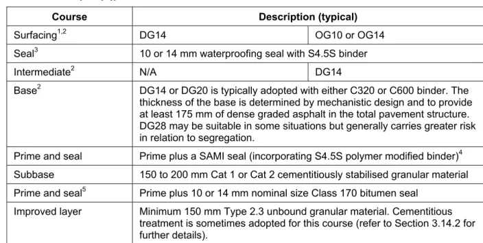
a) Asphalt base over cementitiously stabilised granular subbase (ASt(A)) – this pavement type comprises an asphalt surfacing, asphalt intermediate course (where relevant) and asphalt base, as shown in Table Q2.10. A minimum of 175 mm of dense graded asphalt is typically provided to inhibit cracks in the stabilised subbase reflecting through the asphalt. However, even with this provision, cracking of the cemented material and subsequent reflection into overlying asphalt layers should be anticipated.
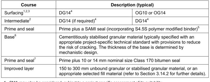
b) Asphalt surfacing over cementitiously stabilised granular base (ASt(B)) – this pavement type comprises an asphalt surfacing and asphalt intermediate course (where relevant) over a cementitiously stabilised base, as shown in Table Q2.11. The total dense graded asphalt thickness is typically less than 175 mm, meaning reflection of cracks through the asphalt should be expected relatively early in the life of the pavement. This pavement type carries similar performance risks as the cemented granular base with sprayed seal surfacing pavement type detailed in Section 2.2.3. This pavement type is typically only adopted where the need for future maintenance interventions has been carefully considered and accepted. Table Q2.10 –Typical structure of asphalt over cementitiously stabilised granular pavement
(ASt(A))
Course Description (typical)
Surfacing1,2 DG14 OG10 or OG14
Seal3 10 or 14 mm waterproofing seal with S4.5S binder
Intermediate2 N/A DG14
Base2 DG14 or DG20 is typically adopted with either C320 or C600 binder. The thickness of the base is determined by mechanistic design and to provide at least 175 mm of dense graded asphalt in the total pavement structure. DG28 may be suitable in some situations but generally carries greater risk in relation to segregation.
Prime and seal Prime plus a SAMI seal (incorporating S4.5S polymer modified binder)4 Subbase 150 to 200 mm Cat 1 or Cat 2 cementitiously stabilised granular material Prime and seal5 Prime plus 10 or 14 mm nominal size Class 170 bitumen seal
Improved layer Minimum 150 mm Type 2.3 unbound granular material. Cementitious treatment is sometimes adopted for this course (refer to Section 3.14.2 for further details).
Notes:
1. SMA may also be considered, subject to a project-specific assessment of its suitability. 2. Refer to Table Q6.7 for further guidance on the selection of binder type in the asphalt layers. 3. Refer to Section 3.7 for further guidance on the inclusion of the waterproofing seal.
4. As an alternative to the SAMI seal, a geotextile reinforced sprayed seal may be provided to further inhibit crack reflection.
Table Q2.11 – Typical structure of asphalt surfacing over cementitiously stabilised granular base pavement (ASt(B))
Course Description (typical)
Surfacing1,2,3 DG144 OG10 or OG14
Intermediate2 DG14 (if required)4 DG144
Prime and seal Prime plus a SAMI seal (incorporating S4.5S polymer modified binder)5 Base6 Cementitiously stabilised granular material typically specified with an
appropriate project-specific technical standard with provisions to reduce the risk of cracking. The thickness of the base is determined by
mechanistic design.
Prime and seal7 Prime plus 10 or 14 mm nominal size Class 170 bitumen seal
Improved layer 150 to 300 mm unbound granular or stabilised granular material, or an appropriate selected fill material (refer to Section 3.14.2 for further details). 1. SMA may also be considered, subject to a project-specific assessment of its suitability.
2. Refer to Table Q6.7 for guidance on the selection of binder type in the asphalt layers. 3. Refer to Section 3.7 for guidance on the use of waterproofing seals.
4. The total thickness of dense graded asphalt (surfacing plus intermediate course) is typically 100 mm for design traffic between 1000 and 3000 ESA/day in the design lane in the year of opening, and 50 mm for traffic less than 1000 ESA/day in the design lane in the year of opening.
5. As an alternative to the SAMI seal, a geotextile reinforced sprayed seal may be provided to further inhibit crack reflection.
6. For temporary pavements, the base typically comprises a minimum 150 mm Cat 1 or Cat 2 cementitiously stabilised granular material (thickness determined by mechanistic design).
7. Refer to Section 3.14.2 for further guidance on priming and sealing the improved layer. 2.3 Overview of pavement design systems
2.3.1 Input variables
Project reliability
The project reliability levels typically adopted by TMR are listed in Table Q2.12. Table Q2.12 – Typical project reliability levels
Road Category Typical Project Reliability Levels (%)
Freeways (Motorways) 95
All other roads (includes highways and
main roads) 90
In both cases, the pavement in the trafficked lane should extend at least 200 mm beyond the delineated edge of the trafficked lane for heavy-duty pavements, and at least 100 mm for other pavements. In some instances it may be beneficial to extend the pavement for the trafficked lane a greater distance into the shoulder to facilitate future widening (for example, to accommodate portable concrete barriers and/or lane realignments).
Where a shoulder of a structural standard lower than that of the adjacent trafficked lane of the pavement is adopted, the following should be provided:
The total pavement thickness of the shoulder should be the same as the adjacent trafficked lane.
Where the adjacent trafficked lane of the pavement is asphalt over granular, full depth asphalt, deep strength asphalt, flexible composite, or similar, the shoulder should have the same asphalt surfacing, seal and intermediate courses as the adjacent trafficked lane. Beneath this, the thickness of asphalt or sealed unbound granular base, should be designed to ensure that the asphalt has acceptable fatigue life. The balance of material down to the top of the granular subbase or improved layer would then typically be a granular subbase material. A pavement drain is typically provided at the interface of the shoulder pavement and adjacent trafficked lane pavement.
Where the adjacent trafficked lane of the pavement is a granular pavement with a sprayed seal or thin asphalt surfacing, the shoulder should have the same asphalt layers and seal as the adjacent trafficked pavement. The shoulder should also have the same granular base layer(s) and materials as the adjacent trafficked pavement. The balance of the thickness of the shoulder to the level of the lowest pavement layer can be a select fill material. General fill may not be appropriate if its permeability is low relative to the adjacent trafficked pavement, as this may inhibit drainage of the pavement layers.
Where the adjacent trafficked lane of the pavement is concrete, a minimum asphalt thickness of 50 mm is typically provided in the shoulder. Where the adjacent concrete pavement also includes an asphalt surfacing, all bituminous layers (such as the surfacing, seal and
intermediate course) are typically also included in the shoulder. Beneath this, the thickness of asphalt or sealed unbound granular base should be designed to ensure that the asphalt has acceptable fatigue life. The balance of material down to the top of the improved layer would then typically be a granular subbase material. A concrete edge drain is typically provided at the interface of the two pavements.
In all cases, it is typical practice to continue the seal to the outside edge of any verge, or if a verge does not exist, to the outside edge of the shoulder.
A lower standard shoulder is not typically used on the high side of one-way crossfalls as this could result in moisture entering the pavement.
Where a shoulder of a structural standard lower than that of the trafficked lanes is constructed as a widening to an existing pavement, the effect of disturbing in situ subgrade materials should be
construction may be more difficult because of increased complexity and narrow working widths
future widening may be more difficult
with concrete pavements, a thicker base course is typically required
temporary trafficking of the shoulder during construction and future maintenance of the through lanes may be restricted, and/or
some shoulders may experience regular trafficking because of the nature of the road alignment (e.g. curves, end of tapers, narrow through lanes, access points, intersections and/or no edge lines).
3. Construction and maintenance considerations
3.1 General
It is assumed that TMR standards for construction and maintenance will be adopted. At the time of publication of this supplement, project-specific technical standards are required for some of the included materials, such as high standard granular material, cementitiously modified granular material, plant-mixed foamed bitumen stabilised material, stone mastic asphalt and multigrade bitumen binder. 3.2 Extent and type of drainage
In addition to the drainage provisions discussed in Part 10: Subsurface Drainage of the Austroads Guide to Pavement Technology (Austroads, 2009), the following cross-sectional provisions should be considered to reduce the exposure of the pavement and subgrade materials to moisture infiltration:
1. Seal over the full width of the formation (traffic lanes and shoulders) 2. On the high side of one-way cross-falls:
provide a low permeability verge (which would typically extend at least an additional 100 m beyond either end from where the transition to a crowned pavement commences);
seal the shoulder and verge, and maintain in a sealed condition, and/or
provide appropriate subsoil drainage to intercept water seepage before it reaches the pavement or subgrade.
3. In cuttings:
provide table drains where an unbound granular pavement is used
provide table drains or subsurface pavement drains where a bound or rigid pavement is used, and
cross- located away from the formation (typically minimum 5 m) in flat or lightly undulating country or excluded altogether
directed away from the formation
appropriately shaped (refer to the TMR Road Drainage Manual), and
such that the invert level is lower than subgrade level in cuttings, to intercept seepage before it reaches the pavement or subgrade. Typically the invert is located at least 200 mm below the lowest pavement layer and improved layer.
8. Compact pavement materials right up to the edge of the pavement to the specified compaction standard, and any excess, poorly compacted paving material beyond the seal edges should be removed.
9. In drier areas (that is, arid and semi-arid areas), particularly if design traffic volumes are less than 106 ESAs, low permeability paving materials may have benefits in relation to reducing
moisture infiltration into the subgrade. However, such materials may have lower strength than standard materials so their suitability should be considered on a case-by-case basis.
10. In situations where the shoulder is narrow and the verge is not sealed, the runoff flow path may be hindered (e.g. by a grassed verge) resulting in moisture entry into the pavement over time. In such situations, consideration should be given to the likely impact on the pavement, in particular unbound pavements.
Moisture from seepage, infiltration through the surfacing and from water table fluctuations, can be controlled by the installation of properly designed pavement and subgrade drains. However, drains are only effective when subgrade moisture is subject to hydrostatic head (positive pore pressures). It is common for fine grained subgrade materials (silts and clays) to have equilibrium moisture contents above optimum moisture content, yet, because pore pressures are not positive, they cannot be drained. While subsurface drainage does play an important role in moisture control, unrealistic assumptions about the effect of subsurface drainage on subgrade moisture condition should not be made.
In some circumstances, subsurface drainage or other types of drainage may need to be constructed well before the pavement to help drain wet subgrades and aid in pavement construction.
The time required to drain a wet subgrade will depend on the permeability of the subgrade material, type and spacing of drains and the extent of additional water in flows. If it is not possible to provide subgrade drainage, or an adequate drainage time, the design should allow for wet conditions, and material types and construction methods should be selected accordingly.
Where pavement or subgrade drainage measures are proposed, the construction sequence should ensure that drainage is installed early enough to prevent a build up of water in the pavement and/or subgrade due to rain during construction.
Consideration should be given to the construction sequence to ensure that drainage installations are not rendered ineffective, even temporarily, by later construction activities. Careful planning in this area
3.2.2 Drainage of pavement materials
Cemented materials can be quite permeable and water has been found to travel long distances within a layer of cemented material. In addition, shrinkage cracks within these materials can become
avenues of rapid moisture movement. Boundaries between layers inadequately bonded together have also been found to allow rapid water movements.
The results of accelerated loading tests (NAASRA, 1987b) as well as observations of field performance have shown that rapid water movement in cemented layers can cause erosion, weakening and subsequent failure of these layers. Thus, if cemented materials are proposed in the pavement structure, consideration should be given to providing effective drainage for these layers.
3.2.3 Use of a drainage blanket
An alternative to an open-graded 20 mm crushed rock is a larger size (typically 125 mm nominal size and 300 mm thick) rock fill. Rock fill is particularly suited to locations with soft subgrades, or where a high drainage capacity is required. The rock fill is typically wrapped in a suitable geotextile and covered by a 150 mm thick cementitiously stabilised granular material to provide a stable platform for pavement construction.
For the purpose of pavement thickness design, crushed rock and rock fill drainage blankets are typically modelled as selected subgrade material with presumptive vertical modulus limited to a maximum of 150 MPa.
3.6 Use of stabilisation
Guidance on the design of pavements with lime stabilised subgrades is provided in TMR Technical Note 74 Structural Design Procedure of Pavements on Lime Stabilised Subgrades (TMR, 2012). Use of multi-layer construction for cemented material courses is not typically adopted for heavy-duty pavements due to the performance risk associated with these layers not remaining fully bonded throughout the pavement’s life.
Accelerated loading tests at Beerburrum (NAASRA, 1987b) clearly illustrated the consequences of inadequate bonding between layers. Measures that have been used to improve the bond between layers in lower traffic situations include:
application of a cement slurry (water cement ratio 0.6 to 0.7) at a rate equivalent to 2 kg of cement per square metre placed immediately before laying subsequent layers, or
using a set retarder in the lower layer and applying the upper layer within approximately 6 hours.
The report Cement Slurry Applications to CTB Layer Bonding (Main Roads, 1988a) describes the use of these measures in more detail.
7% for SM10, DG14, DG20 and DG28 mixes and 8% for DG7 and DG10 mixes. It may take several weeks or months of trafficking, even for dense graded asphalt, before the asphalt surfacing becomes relatively impermeable. Even after this early traffic, any areas of segregation, and particularly areas around construction joints, often remain permeable. To mitigate the risk of moisture ingress, it is typical practice to provide a waterproofing seal under all asphalt surfacings. For unbound granular pavements, a bitumen or lightly modified polymer modified binder is typically used.
Where the layer beneath the asphalt surfacing is also asphalt, the waterproofing seal typically contains an S4.5S polymer modified binder and cover aggregate with a nominal size of 10 mm or larger. The seal should be designed to suit the site conditions and to provide effective waterproofing. The waterproofing seal is typically not required where the following minimum characteristic compaction standards are achieved in the asphalt base, intermediate and surface courses: 94.0% for SM14 mixes, 93.0% for SM10, DG14, DG20 and DG28 mixes, and 92.0% for DG7 and DG10 mixes.
At locations subject to high shear stresses (for example, from heavy braking and/or tight cornering), such as intersections, roundabouts and approaches, the spray rate may need to be adjusted due to the increased risk of shearing. In some atypical situations it may be appropriate to omit the
waterproofing seal to reduce the risk of shearing, while accepting increased risk of moisture ingress. Additional preparative treatment including, but not limited to, texturing the underlying surface and/or use of a propriety bond coat (to bond the asphalt surfacing to the underlying pavement) would typically be required in these circumstances.
Where DG14 is used in surfacing and/or intermediate course in AG(A), ASt(A) and ASt(B) pavements, a minimum compacted layer thickness of 50 mm is typically adopted for the DG14 to aid in achieving adequate compaction and hence inhibit moisture ingress.
DG20 and DG28 layers are particularly prone to moisture ingress when the achieved relative compaction is less than 93.0%. Where this occurs, these layers are typically covered with the next layer of asphalt or a sprayed seal as soon as possible and within 10 calendar days of placement, to reduce the risk of moisture ingress.
3.8 Use of strain alleviating membrane interlayers
SAMI seals are typically applied to the surface of cementitiously stabilised layers to inhibit crack reflection into overlying pavement layers.
3.9 Environmental and safety constraints
Unbound granular pavements are particularly susceptible to damage caused by the infiltration of water during construction, such as from ponded water, seepage and inundation.
Austroads (2003a) provides guidance on the control of moisture in pavements during construction. These factors should be considered during:
selection of pavement type
the construction program minimises the potential for exposure of the pavement to rainfall events and/or inundation
the construction program makes allowance for drying out of pavement layer(s) to below the material’s degree of saturation limit, and
the options, responsibility and liability for any rectification/rework caused by water infiltration and/or inundation during pavement construction is clearly established in the construction contract.
For concrete pavements, the time from commencement of base paving to completion of base paving to the full carriageway width is typically limited to one month, to minimise any problems relating to differential movements. Likewise, for flexible composite pavements the lean concrete subbase is typically covered within one month to assist in limiting the width of shrinkage cracks.
3.11 Construction under traffic
Pavement damage, resulting from temporarily trafficking pavement layers below the final surfacing (including excessive construction traffic), should be included in the pavement design calculations. This may include fatigue damage to asphalt, foamed bitumen stabilised and cemented layers. 3.14 Improved subgrades
3.14.1 Soft subgrades
The selection and design of soft subgrade treatment measures necessitates consideration of project-specific factors including expected construction traffic and the subgrade strength at the time of construction. The subgrade strength at the time of construction may differ to the design subgrade strength used in pavement thickness determination as the design subgrade strength is typically determined on the basis of long-term equilibrium moisture and density conditions, rather than the conditions at the time of construction.
One of the most common soft subgrade treatments is to cover the soft material with a geotextile wrapped granular fill. The granular fill typically comprises a well-graded coarse gravel or crushed rock, or rock fill which has good inter-particle friction. The minimum thickness of material typically required is as shown in Table Q3.1. Rock fill is typically covered by a 150 mm cementitiously stabilised granular material to provide a stable platform for construction of the pavement, including the improved layer (if present).
Table Q3.1 – Typical minimum cover to provide a stable construction platform
In situ subgrade CBR at time of construction (%)
Typical minimum cover to provide a stable construction platform (mm)
1.0 – 1.4 400
For design subgrade strengths of 3% or more, the treatment is typically accounted for as an additional selected subgrade material in the pavement thickness determination. This approach is also applicable when the design subgrade strength is less than 3% and the pavement thickness is determined using Figures 8.4 or 12.2.
For flexible pavements that are designed mechanistically, and where the pavement design subgrade strength is less than 3%, a presumptive subgrade design CBR is typically adopted for an assumed semi-infinite layer which accounts for the combined strength of the soft subgrade and treatment. This is necessary as the standard mechanistic pavement design procedure is based on materials having an elastic response to load, whereas materials with CBR less that 3% are unlikely to behave elastically when loaded.
The presumptive design CBR should be determined by considering the treatment and the likely long-term condition of the materials and subgrade. For example, a presumptive subgrade design CBR of 3% for the assumed semi-infinite layer (that is, from the top of the treatment and extending infinitely below) is typically adopted for the following treatments:
a minimum thickness of coarse granular or rock fill wrapped in geotextile, determined using Table Q3.2
a minimum 200 mm of Category 1 or 2 cemented material over subgrade material with a design CBR of 2 to 3%
a minimum 150 mm of mass concrete (either lean concrete or no fines concrete with geotextile) or sand/cement (12:1) mix over subgrade material with a design CBR of 2 to 3% Table Q3.2 – Minimum thickness of coarse granular or rock fill required for the adoption of a
presumptive design CBR of 3%
Subgrade CBR (%)
(at design density and moisture conditions)
Minimum thickness (mm) of coarse granular or rock fill required for the adoption of a
presumptive design CBR of 3% 1.0 400 1.5 300 2.0 200 2.5 150 3.0 0 An example of the application of this approach to mechanistic design of a flexible pavement is shown
Figure Q3.1 – Example of mechanistic model for a soft subgrade treatment where the CBR of the in situ material at the design conditions is less than 3%
For rigid pavement design, the contribution of a soft subgrade treatment to subgrade strength can be accounted for by applying Equation 25.
In assigning design parameters (for both flexible and rigid pavement design) to the materials used in the soft subgrade treatment, consideration should be given to the impacts of construction traffic and long-term service, recognising that the long-term condition of such materials is likely to be significantly degraded from their initial condition. Typically the materials (including granular, rock fill, and cemented materials) are modelled as sublayered selected subgrade materials with design parameters not exceeding those of a CBR 10% selected fill material.
Where rock fill is used, including in drainage blankets, it is important that the material and cross-section is designed to be free draining throughout the service life of the pavement, taking into consideration issues which may impact on future pavement performance including:
potential for moisture ingress and ability for moisture to drain freely from the material maintenance activities that may impact on drainage (for example, inhibiting drainage as a
result of grading of drains, shoulders and batters)
300 mm (Table Q3.1) 100 mm 200 mm (Table Q3.2) Gravel or rock fill (geotextile wrapped) Soft Subgrade Treatment Mechanistic Pavement Design Model
Selected subgrade material (sublayered) (Section 8.2.2)
Pavement
Improved layer (see Section 3.14.2)
The selected treatment comprises gravel or rock fill in conjunction with subgrade drainage provisions
Assumed semi-infinite subgrade with presumptive
design CBR of 3%
Soft subgrade material
- in situ CBR of 1.5% at time of construction
3.14.2 Improved layers under bound layers
An improved layer is typically included under pavements with asphalt, cemented, foamed bitumen stabilised and/or concrete layers. This is in addition to the soft subgrade treatments detailed in Section 3.14.1.
In heavy-duty pavements this layer has historically been referred to by TMR as the working platform. Such an improved layer:
provides access for construction traffic and minimises the potential for rainfall at critical stages in the construction process to cause subgrade instability and excessive construction delays provides a sound platform on which to construct the pavement layers
protects the subgrade for the life of the pavement structure.
The improved layer in heavy-duty pavements typically consists of a 150 mm (minimum) thick layer of Type 2.3 unbound pavement material that is treated with a cementitious stabilising agent to achieve an unconfined compressive strength of 1.0 to 2.0 MPa at 7 days. In lower-trafficked pavements, an unbound layer is typically adopted. Adoption of an unbound pavement or select fill material under heavy duty pavements is not typically adopted due to its increased risk in relation to moisture sensitivity, which may lead to construction delays and rework.
A more substantial treatment may be needed where:
the in situ strength of the underlying material is less than CBR 7% (at the time of construction) traffic using the improved layer prior to placement of the next structural layer exceeds 1 x 10³
ESA, and/or
required by the contractor for the particular site and construction procedures proposed. It is typical practice to prime and seal (10 mm Class 170 bitumen) the improved layer in the following situations:
Where the probability of rainfall during construction of the improved layer and/or pavement is significant
Where the improved layer is exposed to the environment (ie not covered within a few days of construction) and/or trafficked for an extended period of time, and/or
The improved layer is permeable and/or the layer(s) below the improved layer are sensitive to the effects of moisture ingress.
For other situations the designer should consider the merits of priming and sealing the improved layer giving due consideration to the following:
The cost of the treatment and impact of its inclusion in the design on the construction program, and
3.15 Surfacing type
3.15.1 Sprayed seals
Wherever possible, a prime and seal is typically adopted, rather than a primerseal, due to the
likelihood of enhanced bonding with the underlying pavement. However, a primerseal may be used in some situations, such as where this risk is considered less important than the imperative that the pavement be opened to traffic soon after construction or that the pavement be constructed under traffic.
3.15.3 Open-graded asphalt
Initial construction
A 10 mm or 14 mm dense graded asphalt intermediate course is typically provided under all new pavements that are surfaced with open graded asphalt. Provision of this course enables the open graded asphalt to be fully removed without unduly disturbing the underlying pavement when resurfacing is required.
Q3.17 Settlement
Neither AGPT02 nor this supplement contain provisions for settlement of materials below the
pavement layers. Where required, additional geotechnical investigations and assessments should be carried out to determine if and how much settlement may occur. The amount of settlement permissible typically varies for different pavement types and maintenance strategies. If unacceptable settlement is likely, pre-treatment (e.g. drainage and/or surcharge of the formation) may be required to reduce the extent of settlement after the pavement is constructed.
Q3.18 Pavement jointing considerations
The structural competency of the pavement at longitudinal construction joints is often not as sound as in other areas. As a result, pavements tend to be weaker and more permeable at longitudinal
construction joints. Load induced deformation and/or cracking can occur in these areas.
To reduce the risk of premature distress, construction joints are typically located away from wheel paths. Additionally, construction joints in flexible pavement layers are typically offset from the construction joints in underlying layers using a step-type arrangement.
Q3.19 Thickness of bituminous seals
For the purpose of determining design levels, the thickness of seals and primerseals should be taken as the average least dimension (ALD) of the cover aggregate. If the ALD is not known at the time of design, the ALD can be estimated as 6 mm for 10 mm nominal size cover aggregate and 9 mm for 14 mm nominal size cover aggregate.
minimum, a cemented granular base with asphalt surfacing. An improved layer is typically provided below the stabilised base where the subgrade CBR is less than 5%.
Other temporary pavement alternatives that have been successfully used in high traffic situations include asphalt over granular (AG(A)), asphalt over cementitiously stabilised granular (ASt(A)) and full depth asphalt.
4 Environment
Historical climate data is used to assist with site classification, including the likely moisture and temperature conditions the pavement will experience in service. Further information on climate zones and average conditions is available from the Commonwealth Bureau of Meteorology at
www.bom.gov.au.
Figure Q4.1 illustrates Australian climatic zones on the basis of temperature and humidity. Most of coastal Queensland is classified as having hot humid summers. Western areas have hot summers with either mild or cold winters.
Figure Q4.1 – Australian Climatic Zones () 4.2 Moisture environment
The moisture environment will have an impact on subgrade moisture conditions, drainage requirements and the selection of pavement materials. Volume changes and material strength
Figure Q4.2 illustrates Australian seasonal rainfall zones, based on median annual rainfall and seasonal incidence. Figure Q4.3 provides more detail for Queensland, illustrating median annual isohyets. Rainfall intensity may also impact on moisture conditions within the pavement and subgrade.
Figure Q4.2 – Australian seasonal rainfall zone 4.3 Temperature environment
WMAPTs for additional sites in Queensland are listed in Appendix B of this supplement.
TMR technical standards place limits on temperatures and weather conditions for placing asphalt, seals, cementitiously stabilised and concrete pavement layers. These requirements limit the
detrimental effects that adverse weather conditions can have on the quality and/or performance of the constructed pavement.
Figure Q4.3 – Median Annual Isohyets for Queensland
5 Subgrade evaluation
5.1 General
In addition to assessing subgrade strength, evaluation of the expansive nature of subgrade materials is also important.
Typically the designer will need to include detailed requirements for this reassessment as part of the pavement design solution so that the design can be validated prior to construction.
Subgrade materials are typically assessed using the following measures: soil description and classification
plasticity (plastic limit, liquid limit, and plasticity index) moisture content in situ
particle size distribution
weighted plasticity index (WPI), which is the plasticity index multiplied by the percent passing the AS 0.425 mm sieve
laboratory CBR and swell determined at the design density and moisture conditions, and field CBR tested with a dynamic cone penetrometer (DCP).
When stabilisation of the subgrade material is being considered, additional testing may also be required such as lime demand, sulphate content and UCS. Further guidance on the evaluation of materials for stabilisation is provided in the TMR Pavement Rehabilitation Manual (TMR, 2012).
5.3.5 Moisture changes during service life
Expansive soils
As a consequence of changes in water content, subgrades with expansive soils (including
embankments where expansive soils have not been excluded), can experience considerable volume change that can disrupt the pavement in a number of ways, including:
surface deformation, causing roughness and potential ponding of water
pavement deformation, that can cause loss of density and loss of strength, and
cracking that can allow the infiltration of contaminants (such as water and incompressible material) and also loss of strength.
The magnitude of volume change depends on factors such as: potential swell of the subgrade and/or embankment material extent (width and depth) of expansive material
effectiveness of adopted treatments material density and permeability, and
exposure to, and magnitude of, changes in moisture content (current and future).
project constraints such as time and traffic management.
Where expansive subgrades are present, a geotechnical assessment is typically required to determine the appropriate mitigation strategy, particularly where the expansive nature of the soil is very high (as defined in Table 5.2).
Providing a minimum cover of material over expansive soil is one of the most common techniques used to minimise volume change impacts on the pavement. The required thickness of cover is an output of the geotechnical assessment.
For pavements over subgrades with an expansive nature which is high (as defined in Table 5.2), and where a geotechnical assessment is not undertaken, the following cover thicknesses are typically adopted:
for flexible pavements, the thickness as determined from Figure Q5.1 (which includes the thickness of the pavement and other courses such as select fill, rock fill, treated material and improved layers). Figure Q5.1 assumes that a minimum 150 mm layer of low-permeability subbase, improved layer or select fill is included in the overall structure
for rigid pavements, a minimum cover of 600 mm to the underside of the subbase, including a minimum 150 mm of low permeability material.
These thicknesses are intended to mitigate the risk based on the importance of the road (for example, low risk for heavily trafficked pavements, and higher risk for lower trafficked pavements). However, it may not always be economic to provide these cover thicknesses, particularly for pavements with low traffic and where suitable fill materials are not readily available. In such circumstances, a design solution that accepts the potential impacts and addresses these through appropriate maintenance may be necessary.
For pavements over subgrades with a low or moderate expansive nature (as defined in Table 5.2), additional cover beyond that provided by the pavement and support layers is not typically required.
0 100 200 300 400 500 600 700 800 900 1000
1.E+05 1.E+06 1.E+07 1.E+08
Design Traffic Loading (ESAs)
M inimu m Co ver o ver Ex pa ns iv e M a terial (mm )
Figure Q5.1 – Typical Cover Thickness Over Highly Expansive Material for Flexible Pavements (thickness includes the pavement) (VicRoads, 2010)
The following additional strategies may also be adopted, as appropriate, to aid in minimising volume change in expansive soils:
in embankments, limit the use of highly expansive materials to the core zone (ie use zoned embankments)
control the moisture content of the top 300 mm of the untreated subgrade prior to and during the placement of overlying layers, so that the moisture content after placement of the pavement is as near as possible to the equilibrium moisture content
direct water away from the formation by adopting appropriate geometric design (for example, maximising gradient and crossfall), and/or by adopting drainage provisions that avoid pondage of water within 5 m of the formation
make provision for drying back and re-compacting water-affected subgrades in arid and semi-arid environments:
provide flat embankment batters using low permeability materials (1 on 4 or flatter) and low formation height, wherever possible, as it has been found that shoulder and pavement edge cracking and deformation are more prone to occur as fill height increases and where batters are steeper
1. Test results for the following material properties:
Liquid limit, plasticity index, grading (including determining the percentage of material passing the 2 µm sieve) and weighted plasticity index
Shrink-swell index
Moisture content (including variations in moisture content with depth) Suction and
Clay type (typically determined using x-ray diffraction).
Samples are typically obtained using shallow boreholes with continuous undisturbed sampling. 2. Maintenance history and condition of existing pavements and structures located where similar
soils and moisture conditions are present.
3. Moisture conditions expected at the site, including potential for the material to wet up and dry out during construction and throughout the life of the pavement.
4. TMR performance expectations for the pavement.
Based on the above information, a geotechnical engineer can provide guidance on an appropriate thickness of cover noting:
unbound granular, full depth asphalt and CRCP are less susceptible to structural damage due to subgrade movements than other pavement types
asphalt shape correction treatments typically are not suitable for jointed pavements (PCP and JRCP)
recompacted clays may have a higher potential for movement (in the first few years of wetting and drying cycles) than undisturbed clay subgrades and
procedures for estimating surface movement such as those outlined in AS2870 and Van der Merwe (1964).
5.6 Laboratory determination of subgrade CBR and elastic parameters
Typical pretreatment for materials that breakdown under environmental and service conditions due to weathering (such as shales, claystones, siltstones and other soft laminated or jointed rocks), is to precondition by artificial weathering (10 cycles of soaking for at least 16 hours followed by drying on a hot plate without baking).
For material susceptible to breakdown due to construction procedures and weathering, typical pretreatment involves artificial weathering followed by repeated cycles of compaction.
5.6.1 Determination of density for laboratory testing
Consideration of the compaction requirements in the earthworks technical standard will typically be fundamental in the determination of the compaction standard for CBR testing. Compaction standards for subgrade materials of between 90 and 97% of maximum dry density (MDD) (standard compactive
5.6.2 Determination of moisture conditions for laboratory testing
Site specific information and/or local knowledge is preferred for determining the moisture content to be used. A guide to typical moisture conditions for laboratory CBR testing of subgrade materials is provided in Table Q5.1.
Table Q5.1 – Guide to Moisture Conditions for Laboratory CBR Testing
Location / Circumstances Testing Condition
Locations where all the following are true: Median annual rainfall ≤ 800 mm
Excellent surface drainage and waterproofing Excellent subsurface drainage
Subgrade not significantly affected by the water table, standing water, or ponded water
Subgrade not affected by inundation regularly and/or for extended periods
Experience indicates that unsoaked conditions should apply
Unsoaked
Locations where any of the following are true:
Floodways, causeways and other pavements likely to be inundated regularly and/or for extended periods
Cuttings at or below the water table level that existed prior to the cutting and/or where seepage is likely
Situations where experience indicates that 10 day soaked conditions should apply
10 day soaked
Locations with circumstances not described above, and where experience
indicates that 4 day soaked conditions should apply 4 day soaked Where unsoaked CBR testing is adopted, an investigation into the sensitivity of the material strength to moisture content variations is typically undertaken. For moisture sensitive materials, this typically includes CBR testing at a range of moisture contents and densities. The results of such testing may indicate the need to adopt a CBR that differs from the reported test results (multi-point CBR test results are typically reported at OMC and MDD).
The following points are provided as a guide to the moisture sensitivity of various materials:
sandy (SW, SP) soils – small fluctuations in water content produce little change in volume or strength/stiffness.
silty (SM, SC, ML) soils – small fluctuations in water content produce little change in volume, but may produce large changes in strength/stiffness. Typically these soils attract and retain water through capillary action, and do not drain well.