This guide provides procedures to connect the various components for the Thermo Scientific EQuan™ MAX automated high-throughput LC-MS system.
Hardware
Requirements
The EQuan MAX system supports configurations for the following hardware: • TSQ™ Series mass spectrometer
• Exactive™ mass spectrometer
• Accela™ Open Autosampler (non-DLW option) • Accela 1250 pump
• Accela 600 pump
Software
Requirements
These are the minimum software requirements for operating the EQuan MAX system. • TSQ Series 2.3 SP1
• Exactive 1.1 • Xcalibur™ 2.1 • LC Devices 2.4 • LCQuan™ 2.6
• (Optional) TraceFinder 1.0.1
Instrument
Connections
After installing the software, connect the devices as instructed in the following sections. • Accela Open Autosampler and Valve Connections
• EQuan MAX Plumbing Connections
Accela Open
Autosampler
and Valve
Connections
Assemble the Accela Open Autosampler as shown in Figure 1. For information on how to assemble the Accela Open Autosampler, refer to the Accela Open Autosampler Hardware Manual.
EQuan MAX Getting Connected Field Service Guide
Contents
• Hardware Requirements
• Software Requirements
• Instrument Connections
• Access to CTC Methods and Macros
Figure 1. Accela Open Autosampler
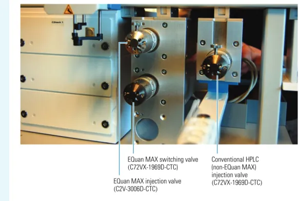
Figure 2 shows the EQuan MAX and conventional HPLC valves. The top-left valve is a low pressure valve (C2V-3006D-CTC) that is used for large volume (EQuan MAX) injections. The valve beneath it is the EQuan MAX 6-port switching valve (C72VX-1969D-CTC). The bottom valve slot on the left is intentionally left empty. Use the single valve on the right side for conventional HPLC (non-EQuan MAX) injections (C72VX-1969D-CTC).
Figure 2. EQuan MAX and conventional HPLC valves
Tip For the TSQ mass spectrometer, the setup in Figure 1 is the most effective because the valves are positioned closest to the source. The most effective setup for the Exactive MS places the valves and wash station to the left side and moves the cooled stack to the right. You can adjust the setup according to the customer’s requirements.
EQuan MAX switching valve (C72VX-1969D-CTC)
Conventional HPLC (non-EQuan MAX)
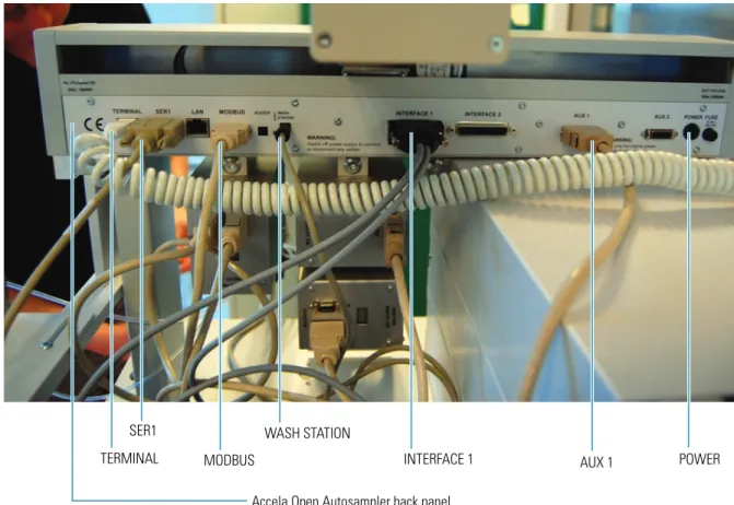
To make connections on the Accela Open Autosampler back panel and in the valve drive modules 1. Connect the TERMINAL port on the Accela Open Autosampler back panel (see Figure 3) to the
handheld controller. The handheld controller is not shown in Figure 3.
2. Connect the SER1 port on the back panel (see Figure 3) to the instrument PC. The PC is not shown in Figure 3.
3. Connect the MODBUS port on the back panel (see Figure 3) to Port A of the non-EQuan MAX injection valve (see Figure 4).
4. Connect the WASH STATION port on the back panel (see Figure 3) to the wash station. The wash station is not shown in Figure 3.
5. Connect the INTERFACE 1 port on the back panel (see Figure 3) to the Accela 1250 Pump using the dual-cable connector. The Accela 1250 Pump is not shown in Figure 3.
6. Connect the AUX 1 port on the back panel (see Figure 3) to the AUX port in the EQuan MAX injection valve drive module (see Figure 4).
7. Connect the POWER port on the back panel (see Figure 3) to the power module box (not shown in Figure 3), which is connected to the power outlet. The POWER port in Figure 3 is not connected.
Figure 3. Accela Open Autosampler back panel connections
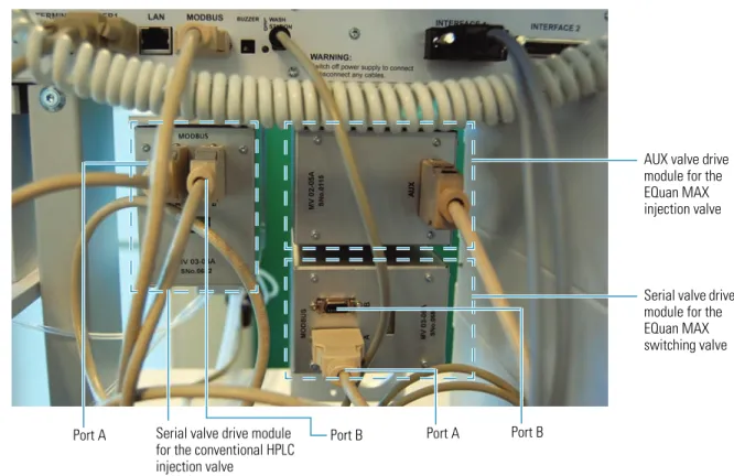
8. Connect the MODBUS port B in the conventional HPLC (non-EQuan MAX) injection valve drive module to the MODBUS port A in the EQuan MAX switching valve drive module (see Figure 4). 9. Connect Port B in the EQuan MAX switching valve drive module (see Figure 4) to the power module
box (not shown in Figure 4), which is connected to the power outlet. Port B of the EQuan MAX switching valive in Figure 4 is currently unconnected.
SER1
MODBUS
WASH STATION
INTERFACE 1 AUX 1
TERMINAL POWER
Figure 4. Valve drive modules and their connections
EQuan MAX
Plumbing
Connections
To connect the EQuan MAX plumbing to the valves
1. Connect Port 5 on the EQuan MAX injection valve to Port 1 (top port) on the EQuan MAX switching valve using the 0.01 in. ID PEEK™ blue tubing. See Figure 5.
Figure 5. Connection of the EQuan MAX injection valve to the EQuan MAX switching valve
AUX valve drive module for the EQuan MAX injection valve
Serial valve drive module for the EQuan MAX switching valve
Serial valve drive module for the conventional HPLC injection valve
Port A Port B Port A Port B
Port 5
Port 1
EQuan MAX injection valve
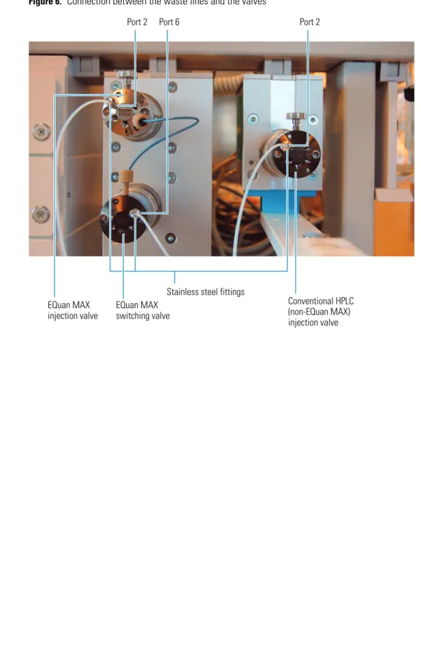
2. Connect all three waste lines to the three valves (Port 2 on the EQuan MAX injection valve, Port 6 on the EQuan MAX switching valve, and Port 2 on the conventional HPLC (non-EQuan MAX) injection valve). See Figure 6. Do not overtighten the stainless steel fittings because doing so can restrict the flow from the valve and cause problems. Fingertight is sufficient. Do not substitute PEEK tubing for the TEFLON™ tubing, as the ID in the PEEK tubing is too restrictive for waste flows.
Figure 6. Connection between the waste lines and the valves
Stainless steel fittings
Port 2 Port 6 Port 2
EQuan MAX injection valve
EQuan MAX switching valve
Conventional HPLC (non-EQuan MAX) injection valve
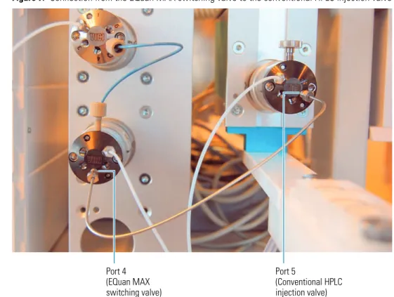
3. Connect Port 4 on the EQuan MAX switching valve to Port 5 on the conventional HPLC injection valve using the metal tubing. This line must be metal because it experiences high pressure (U-HPLC). See Figure 7.
Figure 7. Connection from the EQuan MAX switching valve to the conventional HPLC injection valve
4. Connect the conventional HPLC sample loop to the conventional HPLC valve between Port 3 and Port 6. SeeFigure 8.
Figure 8. Connection for the conventional HPLC sample loop
Port 4 (EQuan MAX switching valve)
Port 5
(Conventional HPLC injection valve)
Port 3 Port 6
Conventional HPLC sample loop
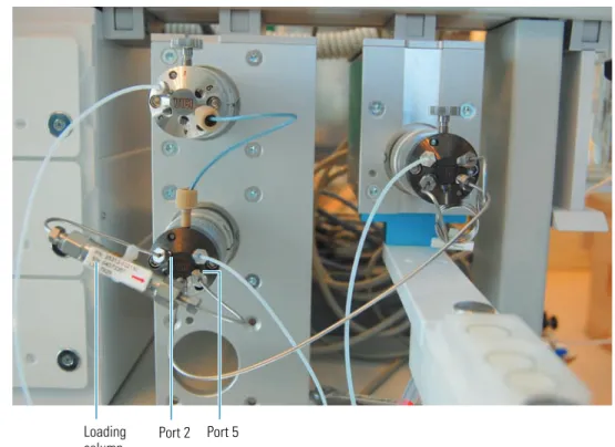
5. Connect the loading column to the EQuan MAX switching valve between Port 2 and Port 5 using the metal tubing. See Figure 9.
Figure 9. Connection for the loading column
6. Connect the EQuan MAX sample loop to the EQuan MAX injection valve between Port 3 and Port 6. There are three types of loops to choose from: 1 mL (the default), 5 mL, and 20 mL. Install the default size unless the customer asks for a different size. See Figure 10.
Figure 10. Connection for the EQuan MAX sample loop
Port 2 Port 5 Loading
column
Port 3 Port 6
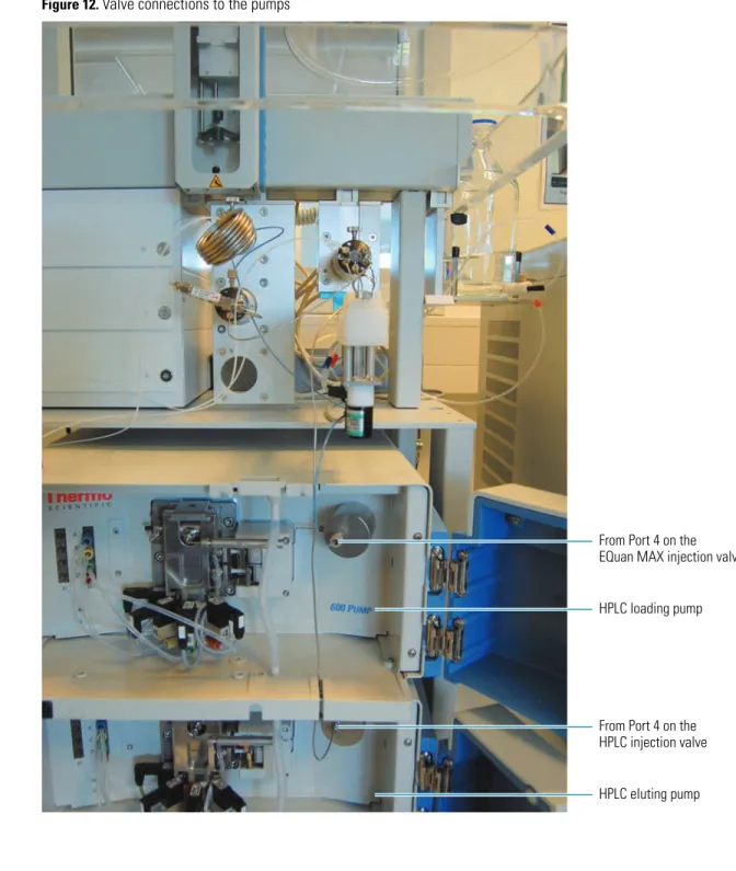
7. Using metal tubing, connect Port 4 on the conventional HPLC injection valve to the HPLC eluting pump (bottom pump). See Figure 11.
8. Using blue tubing, connect Port 4 on the EQuan MAX injection valve to the HPLC loading pump (top pump). See Figure 11. See Figure 12 for the two pumps.
Figure 11. Connections to the pumps
Port 4 To HPLC loading pump
Port 4
To HPLC eluting pump
Figure 12 shows a full view of the valve connections to the two pumps.
Figure 12. Valve connections to the pumps
From Port 4 on the EQuan MAX injection valve
HPLC loading pump
From Port 4 on the HPLC injection valve
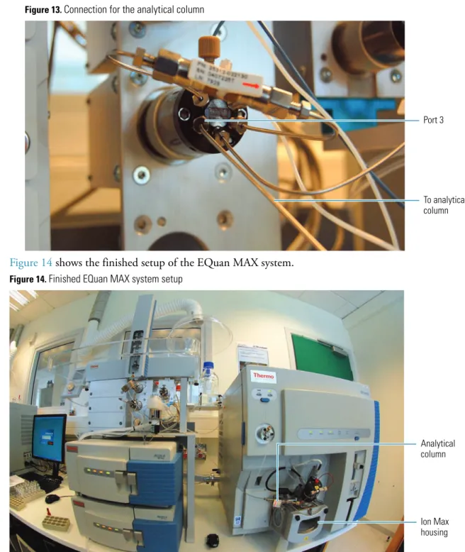
9. Using metal tubing, connect Port 3 on the EQuan MAX switching valve to the analytical column (seeFigure 13). The analytical column is positioned near the Ion Max housing of the mass spectrometer (see Figure 14).
Figure 13. Connection for the analytical column
Figure 14 shows the finished setup of the EQuan MAX system.
Figure 14. Finished EQuan MAX system setup
Checking the
Accela Pump
Connections
To verify the Accela 1250 and 600 pumps are properly connected
1. From the Xcalibur Home Page, click (Instrument Setup).
2. Click (Accela 1250 Pump) in the viewbar of the Thermo Xcalibur Instrument Setup window. 3. Click the Pump General tab.
4. Confirm the Accela 1250 and 600 pumps are available under Pump 1 and Pump 2 (see Figure 15).
Port 3
To analytical column
Analytical column
Ion Max housing
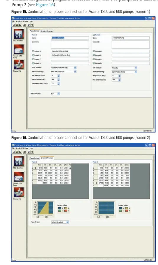
6. Confirm the gradient programs for Accela 1250 and 600 pumps are available under Pump 1 and Pump 2 (see Figure 16).
Figure 15. Confirmation of proper connection for Accela 1250 and 600 pumps (screen 1)
Figure 16. Confirmation of proper connection for Accela 1250 and 600 pumps (screen 2)
Access to
CTC Methods
You can access CTC methods and macros for the EQuan MAX system from the PSE website in the link below: