HAL Id: hal-01265219
https://hal-upec-upem.archives-ouvertes.fr/hal-01265219
Submitted on 1 Feb 2016
HAL
is a multi-disciplinary open access
archive for the deposit and dissemination of
sci-entific research documents, whether they are
pub-lished or not. The documents may come from
teaching and research institutions in France or
abroad, or from public or private research centers.
L’archive ouverte pluridisciplinaire
HAL
, est
destinée au dépôt et à la diffusion de documents
scientifiques de niveau recherche, publiés ou non,
émanant des établissements d’enseignement et de
recherche français ou étrangers, des laboratoires
publics ou privés.
Auto-Adaptive Multi-Sensor Architecture
Ali Isavudeen, Nicolas Ngan, Eva Dokladalova, Mohamed Akil
To cite this version:
Ali Isavudeen, Nicolas Ngan, Eva Dokladalova, Mohamed Akil. Auto-Adaptive Multi-Sensor
Archi-tecture. IEEE International symposium on circuits and systems, ISCAS 2016, IEEE, May 2016,
Montréal, Canada. �hal-01265219�
Auto-Adaptive Multi-Sensor Architecture
Ali Isavudeen
1,2, Nicolas Ngan
1Sagem D´efense et S´ecurit´e
Groupe Safran, Argenteuil, France Email:{ali.isavudeen, nicolas.ngan}@sagem.com
Eva Dokladalova, Mohamed Akil
2Laboratoire Informatique Gaspard Monge, Equipe A3SI
CNRS-UMLV-ESIEE (UMR 8049), Noisy-le-Grand, France Email :{eva.dokladalova, mohamed.akil}@esiee.fr
Abstract—To overcome luminosity problems, modern
embed-ded vision systems often integrate technologically heterogeneous sensors. Also, it has to provide different functionalities such as photo or video mode, image improvement or data fusion, according to the user environment. Therefore, nowadays vision systems should be context-aware and adapt their performance parameters automatically. In this context, we propose a novel auto-adaptive architecture enabling on-the-fly and automatic frame rate and resolution adaptation by a frequency tuning method. This method also intends to reduce power consumption as an alternative to existing power gating method. Performance evaluation in a FPGA implementation demonstrates an inter-frame adaptation capability with a relative low area overhead.
I. INTRODUCTION
From decades, the ability of computer vision systems increases thanks to the multiplication of integrated sensors. Multi-sensor systems enable many high-level vision applica-tions such as stereo vision, data fusion [1] or 3D stereo view [2]. Also smart camera networks take advantage of the multi-sensor concept for large-scale surveillance applications [3]. More and more vision systems involve several heterogeneous sensors such as color, infrared or intensified low-light sensor [4] to overcome the variable luminosity conditions or improve the application robustness.
Frequently, the considered vision system accomplishes various tasks such as video streaming, photo capture or high level processing (i.e. face detection, object tracking, ...). Each one of these tasks imposes different performance computing ability to the hardware resources, according to the applicative context and used sensor. That is why, nowadays vision systems have to be context-aware and to possess the ability to adapt their performance according to the user environment [5]. Fig. 1 illustrates the differences between video and photo user mode parameters: latency, frame rate, resolution, image quality and power consumption. While a video mode needs a high frame rate and low latency, a photo mode rather expects a higher resolution and higher image quality.
In this context, we expect the system architecture adapt itself on-the-fly to the required frame rate or resolution while minimizing the use-case transition time when the user mode changes. In addition, the frame rate and the resolution of the involved sensors are not supposed to be known in advance. Numerous adaptable architectures exist for high-performance image processing [6]–[8] and also even for energy aware heterogeneous vision systems [2], they do not enable such dynamic adaptation of the frame rate or the resolution.
In this paper, we propose a novel pixel frequency tuning approach for heterogeneous multi-sensor vision systems. The
Resolution
Frame rate
Power Image quality
Latency
Photo capture Video streaming low
high
Fig. 1: Photo and video use-case requirements presented architecture enables dynamic auto-adaptation of the frame rate and the resolution. The frequency tuning method is also used to reduce power as an alternative to existing clock or power gating method in stream-oriented computing [9].
The paper is organized as follows. Section II provides the overall description of the proposed auto-adaptive architecture. The adaptation process is presented in section III while perfor-mance evaluation of the proposed solution is given in section IV. Section V draws the overall conclusion of this paper.
II. AUTO-ADAPTIVEMULTI-STREAMARCHITECTURE
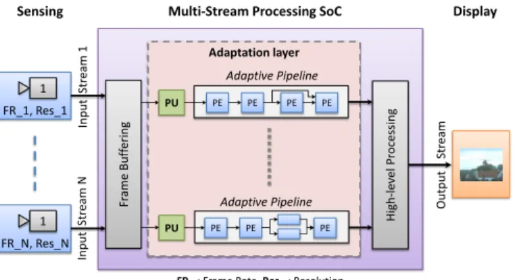
We consider a multi-sensor vision system which is sup-posed to have heterogeneous input streams (Fig. 2). Each input stream differs in either resolution, frame rate or both parameters. It is processed in data-flow oriented Processing Elements (PE), organized in a pipelined structure. The input frames are buffered in frame memory before entering the pipeline. Internal frame synchronisation signal triggers the read operation of the input frames from the frame buffer.
Adaptation layer
Output
Str
eam
FR_: Frame Rate, Res_: Resolution
Multi-Stream Processing SoC
Sensing Display
1 FR_1, Res_1
In
pu
t
Str
eam
1
H
igh
-l
ev
el
P
roc
es
sing
PE PE PE PE Adaptive Pipeline
PE PE PE
Adaptive Pipeline 1
FR_N, Res_N
In
pu
t
Str
eam
N
Fr
ame
B
uf
feri
ng
PU
PU
Fig. 2: Heterogeneous streams vision system
Let consider standard processing pipelines, typically tai-lored for a fixed resolution and they support only a fixed
frame rate. Within a frame period time, the pipeline switches between processing state and idle state. Figure 3 illustrates the processing timing analysis. The global idle state is divided into processing and post-processing idle states. The pre-processing idle state is used for flushing local registers of the PEs between two consecutive frames. In data-flow processing, the post-processing idle state is intended to prepare the wave-form required for the vertical blanking of some specific display protocol (i.e. Video Graphics Array (VGA)). Often, the length of the pre- and post-processing idle states is oversized.
Let call slack-time the span of the post-processing idle state. An unoptimizedslack-timecan significantly decrease the performance of the pipeline. We propose to closely tune the pixel clock frequency (Fpix) to minimize the slack-time, by
reconfiguring the parameters of a reconfigurable Phase-Locked Loop (PLL), according to the user context.
timeline Frame
Sync.
Frame Sync.
1 2 3
Frame Sync.
1 2 3
Overall Idle state
1 Pre-processing
idle state 3
Post-processing idle
state («slack-time »)
2 Frame processing
Fig. 3: Processing and idle state timeline
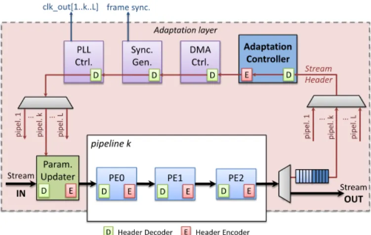
This frequency tuning is handled automatically by the architecture. The principle is based on an on-chip monitoring system and an adaptation layer. Figure 4 depicts an example of a three PEs-based pipeline endowed with the adaptation layer. The on-chip monitoring system is based on a Stream Header
concept already proposed in [10]. However, its utilization is quite different in this framework.
Each image frame of an input stream is headed by the
Stream Header before entering our architecture. Initially, it contains information about the frame rate, the frame width and the frame height of the input stream (Fig. 2). The architecture is aware of the input stream’s characteristics once the Stream Header read.
The reader should notice that the pixel datapath between PEs is supposed to handle both grey level and color pixels. Thus, the data size is designed to support the worst-case pixel granularity. A specific datapath for theStream Headeris used to reach other components involved in the adaptation process outside of the pipeline. At the end point of the pipeline, a demultiplexer lets only the Stream Header go through the adaptation layer while both the Stream Header and the pixel stream are presented in the pixel datapath. Stream Headers of all pipelines of the architecture are timely multiplexed to enter the adaptation layer one-by-one, since this latter is common for all pipelines.
Five other components of the architecture are involved in the adaptation process : the Parameter Updater (PU), the frame Synchronization Generator, the PLL Controller, the DMA Con-troller and the Adaptation ConCon-troller (AC). At each component, a Header Decoder picks up the data that the component needs from the Stream Header while a Header Encoder adds the Monitoring-Data (MD) that the component produces. Thereby, the Header Decoder and the Header Encoder are specific to the component that they are used for.
Adaptation layer
Param.
Updater PE0
D E
PE1
D E
PE2
D E
Adaptation Controller
D E
DMA Ctrl.
D
Sync. Gen.
D
PLL Ctrl.
D
Stream
IN StreamOUT
Stream Header
D Header Decoder E Header Encoder
D E
pipeline k pi
pel
. L
pi
pel
. k
pi
pel
. 1 … …
pi
pel
. k
p
ipel
. 1
pi
pel
. L
… …
clk_out[1..k..L] frame sync.
Fig. 4: Adaptive pipeline architecture
III. AUTO-ADAPTATIONPROCESS
Frame rate and resolution modification will lead to the adaptation of several processing parameters. The key element enabling this adaptation is the Stream Header.
A. Stream Header : on-chip monitoring
The Stream Header is composed of Monitoring-Data. It collects MDs from some components to supply them to other ones. The number of MDs in the Stream Header depends on the complexity of the architecture.
As theStream Headeruses the pixel stream datapath, each MD is embedded into one pixel width. The Stream Header
begins with two start pixels (SP0 and SP1) and it ends with one stop pixel (STP). Figure 5 gives details on the Stream Header. A Monitoring-Data pixel is divided into two parts : MD-Code and MD-Value. MD-Code is SC-bit wide whereas
MD-Value is SV-bit wide. Let SP the size of a pixel in bits.
We have SP =SC+SV. Clk
Input
Str. Header MD0 MD1 MD2 MD3
Output
Str. Header MD0 MD1 MD2 MD3 MD4 MD5
One cycle latency Added MD pixels
SP0 SP1 STP
SP0 SP1 DLY STP
Delay pixel MD-Code MD-Value
Sc Sv
Fig. 5: Stream Header description and timing analysis The Stream Header crosses each adaptation component with one cycle latency (Fig. 5). The last MD of the input
Stream Header is followed by MDs that the component wants to add to the Stream Header.
Some computational delays may be added to the trans-mission of the Stream Header. This delay is used to cover the time that the component needs for any configuration or to compute the Monitoring-Data to be added. A delay is filled with an empty MD pixel (DLY). In the given example, MD4 and MD5 are added after one cycle delay.
B. Adaptation engine
Parameter Updater
The Parameter Updater (PU) is the entry point of the input frames (Fig. 4). This component has local registers where the current frame rate, frame width and frame height of the architecture are saved. The PU compares the parameters of the
input stream with the saved ones in local registers. In case of differences between them, the local registers are updated by the new values.
Moreover, the Parameter Updater sets an update flag in the MD of the corresponding parameter. This update flag
is a single bit information included in the MD-Value of the considered parameter. It will be used later to quickly identify a changed parameter without computing any further comparisons.
Also, The PU adds an identification number of the pipeline (pipeline ID) in the Stream Header. Thispipeline ID is used by the adaptation layer to recognize the source of the Stream Header.
Once leaving the Parameter Updater, the Stream Header
goes through the pipeline and the adaptation layer. Then it comes back to the Parameter Updater thanks to the specific
Stream Header datapath. As long as the stop pixel of the
Stream Header has not reached the Parameter Updater, the input pixels are not introduced in the pipeline. The stop pixel of the Stream Header enables the assertion of aready signal to let the input pixels move into the pipeline. Thisreadysignal asserts the end of the adaptation process.
Processing Element
Each Processing Element uses the frame width and the frame height of the input stream to set their local processing parameters. These parameters mostly concern the size of pixel or line buffers.
Pixel and line counters are used to determine the end of a frame line and the end of a whole frame during the processing. A third clock-cycle counter is used to measure the slack-time. The end of frame triggers the beginning of the
slack-time counter. This counter is stopped by the next frame synchronization signal. Theslack-timeof a given frame period is added in theStream Headerof the next frame. Among slack-times of all PEs, only the least value matters for the concern of the adaptation process. Hence, throughout the pipeline, each PE adds itsslack-timein theStream Headeronly if it is lower than the previous PE’s one.
DMA Controller
Memory slots of the frame memory are designed to support the worst-case frame resolution used in this architecture. As like as the PEs, the DMA Controller picks the frame width and the frame height from theStream Headerto configure the DMA operations. The starting addresses of DMA operations remain unchanged while the lengths are updated.
Synchronization generator
The synchronization signal triggers the beginning of a frame period. This period is determined thanks to a counter whose recycling period can be dynamically modified. The Synchronization Generator uses the frame rate information from the Stream Header to adapt the period of the counter, that is to say the frame period. It converts the frame rate into number of cycles of the counter according toNcounter =
Fclk,counter/F ramerate.
C. Pixel clock frequency tuning
The pixel clock frequency (Fpix) is tuned accurately so
that it is neither lower nor higher than the required frequency. Obviously, if Fpix is lower than the required value, then the
pipeline will not be able to achieve the processing of the whole
frame within the frame period. Meanwhile, a high Fpix will
lead to an extra dynamic power consumption.
Frame Sync
Compute Fpix,req
Increase Fpix
Decrease Fpix
PLL Reconfig. new
Param. ST < STth- ST > STth+
yes no
Fig. 6: Pixel frequency tuning rule
The pixel clock frequency tuning rule is presented in figure 6. The frequency is tuned thanks to a feedback loop on the measured slack-time. Receiving the Stream Header, the Adaptation Controller first checks if any parameter has been updated by the Parameter Updater. In case of new parameters, the AC computes the required minimum pixel clock frequency
(Fpix,req) from the values of the frame rate and the resolution
according to Fpix,req = W idth×Height×F ramerate+
blanking. Some additional cycles are added (blanking) to handle the monitoring latency and line or frame blanking. The number of blanking cycles can be approximated to a given percentage of the frame period.
If the parameters have not been updated, the AC compares the slack-time (ST) to given low and high slack-time thresh-olds (resp. STth− and STth+ ). If the slack-time is lower
thanSTth− or higher than STth+, the AC fires respectively a
frequency increase or decrease request. A PLL reconfiguration will be performed only in case of new Fpix,req or frequency
increase and decrease requests. The PLL Controller computes the required frequency multipliers and dividers according to the input clock frequency of the PLL and the required value
of Fpix,req. The output clock to be reconfigured (fig. 2) is
identified thanks to the pipeline ID.
IV. HARDWAREPROTOTYPING ANDEVALUATION
A. Experimental prototype
The proposed architecture has been implemented on an Altera Cyclone V FPGA (5CGX). We used an experimental prototype with two heterogeneous input streams (color and infrared) and 2 pipelines for each stream. The first pipeline (3 PEs) realizes image restoration while the second one (4 PEs) performs image enhancement. The pipelines have been stressed with several values of frame rate and resolution. The pixel size of the prototype is SP = 36bits with SC = 4bits
andSV = 32bits. TheStream Headerimplementation is given
in table I. The most significant bits of the frame rate’s, the frame width’s and the frame height’s MD-Value are used as the update flag of the respective parameter.
MD MD-Code Size MD MD-Code Size SP0 1111 X Frame width 0010 14 bits SP1 1010 X Frame height 0011 14 bits STP 1110 X Slack-time 0100 32 bits Delay pixel 0000 X Fpix,req 0101 9 bits
Frame rate 0001 10 bits Pipeline ID 0110 4 bits
Start pixels, stop pixel and delay pixel do not use the MD-Value. Only their MD-Code is decoded to recognize them. Hence, the size of their data is not specified in table I. Fpix
increase or decrease commands has the same MD-Code as
Fpix,req but their MD-value is 32 bits wide.
B. Resources utilization
Area overhead of the adaptation engine depends on the pipeline configuration of the case study. Table II gives area overhead of our prototype (4 pipelines, 14 PEs).
Component ALUT Register Memory (bit) Adaptation Controller 224 115 0
PLL Controller 58 21 0
PE adaptation logics (14) 1246 1918 0 Parameter Updaters (4) 28 76 0 Extra adaptation logics 24 16 2304
Total (% FPGA) 1580(2,8%) 2146(0,9%) 2304(0,03%)
TABLE II: Adaptation engine’s area overhead The extra logics added to the DMA Controller and the Syn-chronization Generator are given as Extra adaptation logics. This term also includes pipeline switching logics (multiplexers & demultiplexers). This area result shows an overall overhead less than 4% of the FPGA for a realistic color-infrared dual-stream vision system. An affordable low area overhead per PE (ALUT:89,Regs:137,Mem:0) enables a high scalability for multi-stream systems.
C. Adaptation latency evaluation
Latency penalties due to the adaptation process are reported in table III. Both lines of the table shows the latency cost in terms of clock cycles for each step of the auto-adaptation (resp. Parameter Updater, Processing Element, Adaptation Controller, DMA and Synchronization Generator and PLL Controller).
TP E represents the latency of one PE. In case of new
parame-ters, the most costly adaptation step is the PLL reconfiguration (TP LL). An average PLL reconfiguration time of 257 clock
cycles have been measured. Two more cycles are used to compute PLL frequency dividers and multipliers.
Event TP U TP E TAC Tdma−sg TP LL Ttot No changes 15+tmux 3 6 5 2 31
NewFpix,req 15+tmux 3 6 5 259 288
TABLE III: Adaptation process latency cost
In TP U, an additional tmux multiplexing time has to be
considered in case of Stream Headers queuing at pipeline switching multiplexers stage. This additional time restraints somewhat the scalability of this solution from a latency point-of-view. For usual resolutions and frame rates (QVGA to 1080p and 15 to 100 fps), the adaptation latency remains under 0.4% of the frame period time. Thereby, the presented adaptation process can be performed within an inter-frame time for most of usual configurations.
D. Power analysis
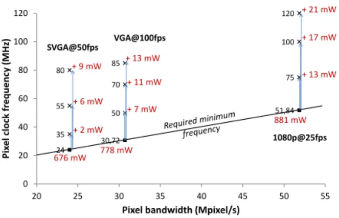
Power savings expected by frequency tuning method have been measured thanks to the Power Monitor tool provided by Altera. Figure 7 exposes the power analysis results. For a given frame rate and resolution, several pixel clock frequencies have been tested. Power consumption with the required minimum frequency has been compared to the one with higher frequen-cies.
30,72 24
51,84 50
35
75 70
55
100 85
80
120
0 20 40 60 80 100 120
20 25 30 35 40 45 50 55
Pix
el
clock
fr
equ
enc
y
(MHz
)
Pixel bandwidth (Mpixel/s)
676 mW 778 mW
881 mW + 2 mW
+ 9 mW
+ 6 mW
+ 7 mW + 13 mW
+ 11 mW + 13 mW
+ 21 mW + 17 mW SVGA@50fps VGA@100fps
1080p@25fps
Fig. 7: Power savings by frequency tuning
Thanks to the frequency tuning method the overall power consumption can be cut up to 2%. One should notice that this percentage is underestimated due to the efficiency of the Power Monitor.
V. CONCLUSION
In this paper an auto-adaptive architecture based on a on-chip monitoring for heterogeneous image streams has been proposed. This architecture enables runtime auto-adaptation of the frame rate and the resolution in a data-flow process-ing thanks to a frequency tunprocess-ing method. This method also attempts to reduce the overall power consumption. Latency penalties and area overhead of the adaptation engine have been evaluated in a FPGA implementation. Performance evaluation demonstrates an inter-frame adaptation capability with a rela-tively low-cost adaptation engine. Promising results for power consumption cutting have been observed. Future works will focus on an efficient adaptive solution for frame buffering in a heterogeneous pixel streams context.
REFERENCES
[1] R. Luo, M.-H. Lin, and R. Scherp, “Dynamic multi-sensor data fusion system for intelligent robots,”IEEE Journal of Robotics and Automa-tion, vol. 4, no. 4, pp. 386–396, Aug 1988.
[2] U. A. Khan, M. Quaritsch, and B. Rinner, “Design of a heterogeneous, energy-aware, stereo-vision based sensing platform for traffic surveil-lance,” inWISES, July 2011, pp. 47–52.
[3] J. SanMiguel, C. Micheloni, K. Shoop, G. Foresti, and A. Cavallaro, “Self-reconfigurable smart camera networks,”Computer, vol. 47, no. 5, pp. 67–73, May 2014.
[4] H. Ngo, L. Tao, M. Zhang, A. Livingston, and V. Asari, “A visibility improvement system for low vision drivers by nonlinear enhancement of fused visible and infrared video,” inCVPR, June 2005, pp. 25–25. [5] H. W. Gellersen, A. Schmidt, and M. Beigl, “Multi-sensor
context-awareness in mobile devices and smart artifacts,”Mobile Networks and Application, vol. 7, no. 5, pp. 341–351, Oct. 2002.
[6] T.-Y. Cheng, T.-H. Chen, J. Chen, and S.-Y. Chien, “Coarse-grained reconfigurable image stream processor architecture for high-definition cameras and camcorders,” inISOCC, Nov 2010, pp. 95–98.
[7] F. Pelissier and F. Berry, “Design of a real-time embedded stereo smart camera,” inAdvanced Concepts for Intelligent Vision Systems, ser. LNCS. Springer, 2010, vol. 6474, pp. 344–356.
[8] J. van der Horst, R. van Leeuwen, R. K. H. Broers, and P. Jonker, “A real-time stereo smartcam, using fpga, simd and vliw,” in2nd Workshop on Applications of Computer Vision. Springer, May 2006.
[9] M. Hosseinabady and J. L. Nunez-Yane, “Energy optimization of fpga-based stream-oriented computing with power gating,” inFPL, 2015. [10] N. Ngan, E. Dokladalova, and M. Akil, “Dynamically adaptable noc
router architecture for multiple pixel streams applications,” in IEEE Int. Symp. on Circuits and Systems, ISCAS, 2012, pp. 1006–1009.