Renewable Energy System with High performance Hybrid
Cascaded Inverter
Azaruddin Shaik1, Sk Gouse Basha2, Prasanthi M3, Ravi Kumar Reddy P4 1*Pursuing M.Tech in the field of Power Electronics
2*Working as, Assistant professor in the EEE Dept, NCET, Vijayawada, AP 3*Pursuing M.Tech in the field of Power & Industrial Drives
4*Working as, PPC In-charge in Transformers manufacturing Industry, AP, Ind
ia
ABSTRACT:
In this paper, Renewal energy system with high performance Hybrid cascaded inverter is proposed. It is based on two kinds of power devices those are MOSFET and IGBT and also the cascaded inverter consists of three H-bridges. The DC voltage of each H-bridge meets the proportional relationship of 1:2:4 and the three modules are connected in series at the AC side. The low voltage bridge is composed of MOSFETs, while the medium and high voltage bridges are composed of IGBTs. This hybrid cascaded inverter can output at most 15 voltage levels at the AC side with rather low switching frequency. At the same time, it can fully exhibit the advantages of different power devices and make the inverter operation flexible. Voltage gradational and PWM carrier modulation methods are adopted in this paper.
With different combination of switching states, the distribution of input active power in each H-bridge can be adjusted. As a result, for renewable energy system, larger control freedom is provided and the need of power balance is satisfied. The inverter system is verified with simulation results.
I.INTRODUCTION:
Voltage source inverter is commonly used as the interface to connect the renewable energy source and the power grid. In order to improve the performance of renewable energy system, the topology and control method of the inverter system need to be analyzed.
Hybrid cascaded inverter:
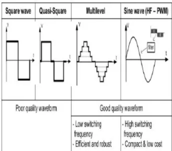
Inverters can be classified by their output waveform in four categories: square wave, customized square wave, also called quasi-square wave, multilevel and sine wave (synthesized from a high frequency PWM), as shown in Table 1. Though the square and quasi-square wave inverters can be accepted in some applications, and are obtainable in the market, they are not recommended due to their poor quality waveform. Multilevel and sine wave inverters are considered the state of the art technology. The main dissimilarity between the two topologies is the switching frequency, the previous based on low frequency while the later based on highswitching frequency. Multilevel inverters are the best available solution for high power applications. However, for medium and low power applications, there is not an apparent tradeoff to make it more appealing than sine wave inverters, or vice versa. Elevated frequency inverters favor compactness and reduced cost, while low frequency ones are claimed to have the best efficiency and robustness. The final choice of one inverter instead of the other better depends on the application.
Table 1: Inverter topologies by waveforms
hybrid cascaded inverter (HCI) is accomplished. The hybrid structure is shown in two aspects. Firstly, the DC buses have hybrid voltages. They are V0, 2V0 and 4V0 respectively. Secondly, hybrid power devices are adopted. For DC buses with different voltages are employed, more voltage levels can be reached at the AC side, with rather lower switching frequency. As a result, the output harmonic loss and the switching loss are lower down. At the same time, for different kinds of power switches are employed, the performance of the inverter system can be further improved. According to the selected modulation method, the switching frequency in the three H-bridges are different. InV0 H-bridge, the DC bus voltage is lower and the switching frequency is higher, so power MOSFET is adopted. On the other hand, in 2V0 and 4V0 H-bridges, the DC bus voltage is higher and the switching frequency is lower, so IGBT is adopted. With the above combination of power switches, the advantages of different devices can be shown and the system loss is further lowered down. The high efficiency operation of the inverter system can be reached.
Compared with conventional two-level inverter, HCI has several advantages. They’re flexible choice of devices, low voltage rating for each power switch, low output harmonic content, low switching frequency and so on. At the same time, it should be emphasized that with the rapid progression of renewable energy generation system, the concept of ‘Micro-grid’ is highly concerned worldwide. ‘Micro-grid’ includes several micro-sources inside and the above structure of HCI has several DC input ports. As a result, HCI is suitable for the application of Micro-grid. Its DC side can be easily connected to the micro-sources with DC voltage output. In this paper, a 2kW single-phase HCI is implemented. It is based on low-loss MOSFET (offered by IXYS Co.) and V-IGBT (offered by Fuji Electric Co.). Voltage gradational and PWM carrier modulation methods are employed. The realization process of the two methods is shown theoretically. The structure of HCI and the two modulation methods are validated by simulation.
II.PROPOSED SCHEME OF HCI & ITS
MODULATION METHOD AND ITS
DESCRIPTION:
The structure of the HCI is composed of three H-bridges, as shown in Fig.1.
H-bridge: An H-bridge is an electronic circuit which enables a voltage to be applied across a load in either direction. These circuits are often used in robotics and other applications to allow DC motors to run forwards and backwards. H-bridges are available as integrated circuits, or can be built from discrete components. General The term "H-bridge" is derived from the typical graphical representation of such a circuit. An H-bridge is built with four switches (solid-state or mechanical). When the switches S1 and S4 (according to the first figure) are closed (and S2 and S3 are open) a positive voltage will be
applied across the motor. By opening S1 and S4 switches and closing S2 and S3 switches, this voltage is reversed, allowing reverse operation of the motor. Using the nomenclature above, the switches S1 and S2 should never be closed at the same time, as this would cause a short circuit on the input voltage source. The same applies to the switches S3 and S4. This condition is known as shoot-through.
Construction: A solid-state H-bridge is typically constructed using reverse polarity devices (i.e., PNP BJTs or P-channel MOSFETs connected to the high voltage bus and NPN BJTs or N-channel MOSFETs connected to the low voltage bus). The most efficient MOSFET designs use N-channel MOSFETs on both the high side and low side because they typically have a third of the ON resistance of P-channel MOSFETs. This requires a more complex design since the gates of the high side MOSFETs must be driven positive with respect to the DC supply rail. However, many integrated circuit MOSFET drivers include a charge pump within the device to achieve this. Alternatively, a switch-mode DC-DC converter can be used to provide isolated ('floating') supplies to the gate drive circuitry. A multiple-output fly back converter is well-suited to this application. Another method for driving MOSFET-bridges is the use of a specialised transformer known as a GDT (Gate Drive Transformer), which gives the isolated outputs for driving the upper FETs gates. The transformer core is usually a ferrite toroid, with 1:1 or 4:9 winding ratio. However, this method can only be used with high frequency signals. The design of the transformer is also very important, as the leakage inductance should be minimized, or cross conduction may occur. The outputs of the transformer also need to be usually clamped by zener diodes, because high voltage spikes could destroy the MOSFET gates.
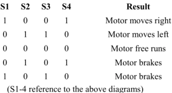
Operation:The two basic states of an bridge, The H-Bridge arrangement is generally used to reverse the polarity of the motor, but can also be used to 'brake' the motor, where the motor comes to a sudden stop, as the motor's terminals are shorted, or to let the motor 'free run' to a stop, as the motor is effectively disconnected from the circuit. The following table summarises operation.
S1 S2 S3 S4 Result
1 0 0 1 Motor moves right 0 1 1 0 Motor moves left 0 0 0 0 Motor free runs
0 1 0 1 Motor brakes
1 0 1 0 Motor brakes
(S1-4 reference to the above diagrams)
The structure of the HCI is composed of three H-bridges, as shown in Fig.1. They have isolated DC buses and the voltages areV0, 2V0 and 4V0 respectively. And at the AC side, three H-bridges are connected in series. Concretely,V0 H-bridge is based on MOSFET, while 2V0 and 4V0 H-bridges Are based on V-IGBT. In the paper, two kinds of modulation methods are employed. First is voltage gradational method and second is PWM carrier method. In voltage gradational method, Vis supposed to be the required voltage at the AC side. It is the superposition result ofV0, 2V0 and 4V0, as shown in (1). Here, coefficientsx,yand zequal to 1, -1 or 0. ‘1’, ‘-1’ and ‘0’ mean the H-bridge outputs positive, negative and zero DC bus voltage, respectively. It can be analyzed that to each needed voltage at the AC side, several superposition ways can be reached sometimes. For example, V0 has three superposition methods. They can be shown as ‘V=1·V0+0·2V0+0·4V0’, ‘V =(-1)·V0+1·2V0+0·4V0’ and ‘V=(-1)·V0+(-1)·2V0 + 1·4V0’. In this way, some redundant states can be reached. The operation of HCI is more.
The realization process of voltage gradational modulation method can be shown as follow. Firstly, according to the actual required amplitude and frequency, confirm the ideal Instantaneous voltage value. Secondly, divide the ideal instantaneous voltage by the reference voltageV0. Round the result and get the voltage level to the instantaneous voltage. Finally, confirm the concrete output voltage of each H-bridge and the concrete state of each power switch. In order to lower down the contents of low frequency harmonic components, PWM carrier modulation method is employed. In this method, the outputs of 2V0 and 4V0 H-bridges are kept same as voltage gradational method. The sum of the above two output voltage waveform has seven level staircases. The ideal sinusoidal waveform minus the seven-level staircase waveform reaches the modulation wave in V0 H-bridge. So, PWM method is employed and the sum of the output waveforms in three H-bridges approximates to the ideal
sinusoidal wave. Also, supposeV is the object voltage at the AC side, as shown in (1). With PWM carrier modulation method, in the positive half period, the coefficientsyandzare confirmed as shown in (2). From (2), the output of 2V0 and 4V0 H-bridges are reached. The corresponding output voltage inV0 H-bridge is got by the comparison of the above modulation wave and triangle carrier wave.
III. POWER BALANCE CONTROL
METHOD IN HCI:
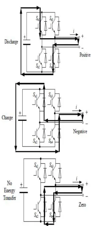
In voltage gradational modulation method, there are several redundant superposition methods. The unneeded states can be utilized. As commonly known, one H-bridge can output three kinds of voltages. They are positive DC bus voltage, negative DC bus voltage and zero. Presume the direction of the load current is shown in Fig3.1 (When the direction of the load current changes, the same analyzing process can be reached.). When positive voltage is arriving at the AC side, the DC bus provides active power and the capacitor is discharging. At the similar time, when negative voltage is reached, the DC bus absorbs active power and the capacitor is charging. When zero voltage is reached, no active power is transferred in the DC bus capacitor. The redundant states can be utilized. As commonly known, one H-bridge can output three kinds of voltages. They’re positive DC bus voltage, negative DC bus voltage and zero. Suppose the direction of the load current is shown in Fig.2 (When the direction of the load current changes, the same analyzing process can be reached.). When positive voltage is reached at the AC side, the DC bus provides active power and the capacitor is discharging. At the same time, when negative voltage is reached, the DC bus absorbs active power and the capacitor is charging. When zero voltage is reached, no active power is transferred in the DC bus capacitor.
Fig 2: Active power transfer in DC bus with different AC output voltages.
HCI has several DC input ports. In the actual application, the DC bus can be connected to different kinds of sources. For example, it can be connected to photovoltaic (PV) panel, storage battery, and so forth. As known that, storage battery can store energy when the input energy is adequate in the inverter system, such as sufficient light for PV system. On the other hand, it can release energy when the input energy is inadequate. As a result, with different external conditions, the distribution of active power at the DC side should be adjusted accordingly. Take the following system as an example. The DC buses of V0and 2V0H-bridges are connected to
storage battery and the DC bus of 4V0 H-bridges is
connected to PV panel. When sufficient sunlight is received in the system, 4V0H-bridge should provide more
active power, while at the same time, V0 and 2V0
H-bridges should absorb active power and store energy. When no enough sunlight is received, 4V0 H-bridge
should provide less active power and the other two bridges with storage batteries should provide more. The above power balance process is reached by selecting different superposition methods. Also, when starting up HCI, the DC bus capacitor should be precharged. It can be simply accomplished by selecting different superposition methods. Also take the above situation as an example. When starting up the HCI, the precharging process can be reached by selecting the superposition method of (x, y, z) = (-1,-1, 1). Here, (x, y, z) represents the concrete superposition method. It means that V0, 2V0and 4V0
H-bridges output negative, negative and positive DC bus voltage. So the active power in 4V0Hbridge flows to the
V0 and 2V0H-bridges. Three DC bus capacitors are pre
charged by the PV panel connected to 4V0DC bus. Define
the voltage utilization ratio of HCI as follow in (3). Here, ‘m’ represents voltage utilization ratio. Udcx (x=1, 2, 3) represents DC bus voltage. Uac represents the rms value of AC voltage.
So, in simulation, with voltage gradational method, m equals to 0.71, while with PWM carrier method, m equals to 0.65. And in experiment, with voltage gradational method, mequals to 0.76, while with PWM carrier method, m equals to 0.68. It can be concluded that simulation and experiment results are approximately in accordance and voltage gradational method has higher voltage utilization ratio than PWM carrier method.
further less than that in IGBT bridge. As a result, the reverse recovery loss of the free-wheeling diode in MOSFET bridge is ignored. Here, ‘WconT’, ‘WonT’ and ‘WoffT’ are the steady loss, turn-on loss and turn-off loss of IGBT respectively. ‘WconMOS’ and ‘WtranMOS’ are the steady loss and transient loss of power MOSFET. ‘WconD’ is the steady loss of free-wheeling diode in both bridges and ‘WrrD’ is the reverse recovery loss of free-wheeling diode in IGBT bridge. ‘Vcc’ is the actual DC bus voltage and ‘Vref’ is the DC bus voltage shown in the datasheet; ‘i’ is the current flowing through the power switch. ‘Rd’ is the on-state resistor of MOSFET. In (8), ‘uDS’ is the voltage across terminal ‘D’ and ‘S’ when MOSFET is turned off and ‘iD’ is drain current when MOSFET is turned on. At the same time, ‘ttran’ is the time-span of the turn-on or turn-off process. In (4), (7) and (9), ‘ts’ is the control period. The other parameters are the undermined coefficients. Then, according to the datasheet of V-IGBT and low loss MOSFET, by curve-fitting, the undetermined coefficients can be reached. So, the system power loss and efficiency can be achieved.
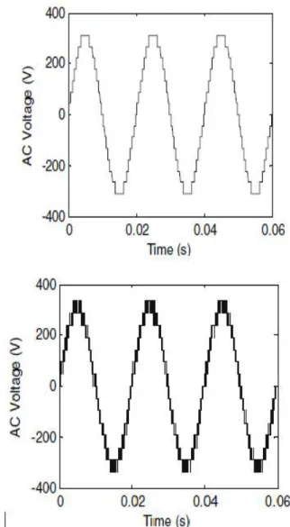
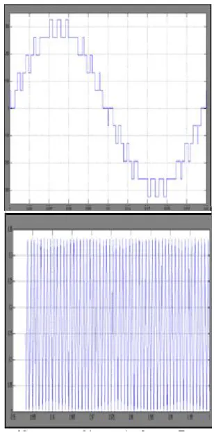
IV. SIMULATION RESULTS:
Fig: Simulation results of AC output voltage waveform with (a) voltage gradational method and (b) PWM carrier
method.
V. CONCLUSION:
In this paper, the topology and modulation method of a single-phase HCI are discussed. Concretely, hybrid power devices are involved. InV0 H-bridge, power MOSFET is adopted while in 2V0 and 4V0 H-bridges, IGBT is employed. In order to improve the performance of the renewable energy system, HCI is employed. The HCI is composed of three H-bridges. The DC voltage of each H-bridge meets the proportional relationship of 1:2:4 and their AC sides are connected in series. As a result, it can output more voltage levels at the AC side with lower switching frequency. At the same time, voltage gradational and PWM carrier modulation methods are adopted and discussed in detail in the paper. The results are clearly verified with simulation results.
VI. REFERENCES:
[1] F. Blaabjerg, R. Teodorescu, M. Liserre and A.V. Timbus. “Overview of control and grid synchronization for distributed power generation systems,” IEEE Transactions on Industrial Electronics, Vol.53, No.5, 2006:1398-1409.
[2] E. Figueres, G. Garcera, etc. “Sensitivity study of the dynamics of three-phase photovoltaic inverters with an LCL grid filter,” IEEE Transactions on Industrial Electronics, Vol. 56, No. 3, 2009:706-717.
[3] M. Aiello, A. Cataliotti, S. Favuzza, etc. “Theoretical and experimental comparison of total harmonic distortion factors for the evaluation of harmonic and interharmonic pollution of grid-connected photovoltaic systems,” IEEE Transactions on Power Delivery, Vol.21, No. 3, 2006:1390-1397.
[4] S.B. Kjaer, J.K. Pedersen and F. Blaabjerg. “A review of single-phase grid-connected inverters for photovoltaic modules,” IEEE Transactions on Industry Applications, Vol.41, No.5, 2005:1292- 1306.
[5] J. M. Guerrero, J. C. Vasquez, J. Matas, etc. “Control strategy for flexible microgrid based on parallel line-interactive UPS system,” IEEE Transactions on Industrial Electronics, Vol.56, No.3, 2009:726- 736.
[6] I.Y. Chung, W.X. Liu, etc. “Control methods of inverter-interfaced distributed generators in a microgrid system,” IEEE Transactions on Industry Applications, Vol.46, No.3, 2010:1078-1088.
[7] J.C. Vasquez, J.M. Guerrero, A. Luna, etc. “Adaptive droop control applied to voltage-source inverters operating in grid-connected and islanded modes,” IEEE Transactions on Industrial Electronics, Vol.56, No.10, 2009:4088-4096.
AUTHOR PROFILE:
1*AZARUDDIN SHAIK pursuing M.Tech in Nimra College of Engineering and Technology, Vijayawada. His specialization is Power Electronics. He graduated in Electrical and Electronics Engineering from JNTU Kakinada. His research interest includes Power Electronics and Applications.
2*SK GOUSE BASHA is currently working as a Assistant Professor in Electrical and Electronics Engineering Department, Nimra College of Engineering and Technology (NCET), Vijayawada. He obtained his M.Tech Degree & B.Tech degree in Electrical and Electronics Engineering from NCET, Vijayawada, JNTU Kakinada. His research interest includes Power Electronic Converters and applications.
Kakinada. His specialization is Power & Industrial Drives. He graduated in Electrical and Electronics Engineering from JNTU Hyderabad. His research interest includes Power Electronic Converters and drives.