Soufiane Zahid
1, Abdeslam En-Nouaary
1and Slimane Bah
2 1Institut National des Postes et Télécommunication, Rabat, Morocco2Ecole Mohammadia d'Ingénieurs, University Mohammed V, Rabat, Morocco
Practical Model Checking of a Home
Area Network System: Case Study
The integrated communication infrastructure is the core of the Smart Grid architecture. Its two-way com-munication and information flow provides this net-work with all needed resources in order to control and manage all connected components from the utility to the customer side. This latter, named the Home Area Network or HAN, is a dedicated network connecting smart devices inside the customer home, and using different solutions. In order to avoid problems and anomalies along the process life cycle of developing a new solution for HAN network, the modeling and validation is one of the most powerful tools to achieve this goal. This paper presents a practical case study of such validation. It intends to validate a HAN SDL model, described in a previous work, using model checking techniques. It introduces a method to trans-late the SDL model to a Promela model using an inter-mediate format IF. After the generation of the Promela model, verification is performed to ensure that some functional properties are satisfied. The desired proper-ties are defined in Linear Temporal Logic (LTL), and DTSPIN (an extension of SPIN with discrete time) model checker is used to verify the correctness of the model.
ACM CCS (2012) Classification: Software and its engineering → Software organization and properties → Software functional properties → Formal methods → Model checking
Networks → Network types → Home networks
Keywords: Smart Grid, Promela generation, Formal modeling, V&V, SPIN, LTL
1. Introduction
Smart Grid is an intelligent power network based on information and communication technologies in order to monitor, optimize and control all functional units from electricity gen-eration to end-customers. Many internation-al organizations and government institutions around the world have been encouraging the use of Smart Grids, and proposed their own models and roadmaps for this. In particular, the end-user side, or Home Area Network (HAN), represents a challenge for these organizations in order to help customers to reduce their ener-gy consumption and cost, and to maximize the transparency and reliability of the energy sup-ply chain.
● IHD: or In-Home Display which is an in-terface to control the appliances and show statistics,
● HEMS: or Home Energy Management System, it stores data about all the con-nected appliances and PEV, and manages the DR signals from the utility,
● SM: or Smart Meter, it displays the energy consumption of the customer,
● ESI: or Energy Services Interface, which plays the role of the gateway between the home and the utility network.
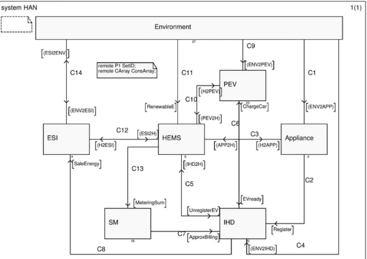
The SDL system interacts with system envi-ronment via 5 channels. Channels C1, C4 and C9 represent the customer interaction with the HAN; channel C11 is related to the energy gen-erated by renewable sources; and the last one is C14 which connects the HAN with the NAN. This model was verified using the reachability analysis techniques and the verification against a given MSC (Message Sequence Charts) in order to detect dead blocks and verify specific scenarios, respectively [3]. However, no veri-fication of the system behavior has been made yet. In fact, the SDL language does not allow such verification [4]. Therefore, this paper in-tends to perform model checking [11] to verify the model behavior. For this purpose, one of the existing model checkers must be chosen.
Model checkers are the tools that help in this type of formal verification. In literature, there is a very large number of these tools. Authors in [12] compared six model checkers, namely: Al-loy [13], CADP [14], FDR2 [15], NuSMV [16], Programs and Time-based Programs; each
cate-gory contains several programs [7].
This architecture was modeled using the SDL language [8]. The latter is a standard language for specification and description of reactive and distributed systems. A model described in SDL is composed of one or several blocks. Each block contains either other blocks or processes. The behavior of the processes is detailed using Extended Finite State Machine (EFSM) [9]. Un-like FSM that always performs a transition on a given input from one state to another, an EFSM however only performs a transition when a giv-en set of conditions have begiv-en satisfied. It means that the transition can be expressed by a set of trigger conditions (e.g. if statements). If trigger conditions are all satisfied, the transition is fired, bringing the machine from the current state to the next state and performing the specified data operations. On the other hand, the procedure be-havior is described by FSM. It is similar to the one known from programming languages. It is created when a procedure call is interpreted, and it dies when it terminates. Signals in the system are exchanged between blocks via channels, and between processes via signal routes. Figure 1 re-sumes this architecture [10].
The SDL model of the HAN architecture, cited in a previous contribution [3], consists of six blocks as shown in Figure 2. Each entity rep-resents one of the HAN's components, namely: ● Appliance: refers to all devices inside the
home,
● PEV: or Plug-in Electrical Vehicle, The HAN network is one of the most important
parts in Smart Grid. Many researches around the world are focusing on this network and they are trying to investigate its potential benefits for both customers and providers. So, the analysis of the previous architecture was started by modeling the HAN network [3] using SDL (Specification and Description Language). Then, the resulting model was verified and validated by the reach-ability analysis technique, with the support of IBM Rational SDL suite, to detect dead blocks and to ensure that all the branches are reachable. The bit-state exploration was used to find un-explored branches in the model. If they were found, the model was corrected and the verifica-tion was rerun until a model free of dead blocks was obtained. However, at this stage, the prop-erties of the system have not been verified yet. In fact, the task of validating implementation of the model is generally much harder. This paper focuses only on some properties in relation with the Demand Response service (which will be described in the next section). These properties will be detailed later. Unfortunately, the SDL language does not allow such validation [4]. This work aims to perform the model checking [5] step using an extension of one of the most powerful tools in this field, which is SPIN mod-el checker. It will be used to verify the desirable temporal properties of the model, expressed as LTL formulas, to evaluate the system require-ments. The SDL model must be translated into Promela (the input language for SPIN), how-ever, this translation is not as trivial as it may seem. There are some fundamental differences between these two languages. In fact, SDL sup-ports hierarchical structure, whereas Promela is a flat language, with one level of hierarchy. Also, some SDL data types and constructs can-not be represented trivially in Promela, because they usually include additional information in relation with the system hierarchy.
This case study introduces one approach to generate the Promela model from the SDL one, using an intermediate format IF. The reason be-hind this choice is that the transformation from SDL to IF is intuitive and simple compared to the translation from SDL to Promela directly. Also, it provides a common model between various languages adopting different descrip-tion styles (e.g. SDL, UML). After the trans-lation of the SDL model into Promela,
verifi-cation is done to ensure that some functional properties, represented as LTL properties, are satisfied. This approach can be applied to any model developed in the SDL language.
The remainder of this paper is organized as fol-lows. The next section presents the background of the work. It gives a brief description of the HAN architecture and its SDL modeling, then, it introduces some works related to Prome-la generation from SDL. Section 3 details the translation approach via two big steps. The first step highlights transformation of the SDL mod-el into the intermediate format IF. It explains some translation features concerning the struc-ture, the behavior and the data. The second one introduces the if2pml tool used to generate the Promela model. Section 4 presents the model checking of the generated model. It describes some LTL properties to be checked and the re-sult of this verification. The last section con-cludes the paper and presents the future works.
2. Background
The Home Area Network or HAN is the cus-tomer side in a Smart Grid network. It is con-tained within the user's home and connects all appliances and electrical vehicles to a common network. It contains other solutions, such as software applications to manage and control these devices, as well as renewable energy re-sources and energy storage equipment.
A previous work [1] presented HAN architec-ture and its mandatory and essential compo-nents. It introduced the possible and well-used communication technologies and standards for each section. This architecture brings a lot of benefits to the customers. They can take advan-tage of the services provided by utilities. The most important one is the service DR (Demand Response). It is responsible for reducing the peak loads, when the network is under stress, by minimizing the energy consumption in response to an increase in the price of electricity [6]. So, each customer may participate in one or more DR programs. The raisons behind encouraging customers to participate in such programs are different. They help them reduce the bills price, avoid blackouts and increase their sense of re-sponsibility. DR programs are classified into two major categories, namely Incentive-based
● IHD: or In-Home Display which is an in-terface to control the appliances and show statistics,
● HEMS: or Home Energy Management System, it stores data about all the con-nected appliances and PEV, and manages the DR signals from the utility,
● SM: or Smart Meter, it displays the energy consumption of the customer,
● ESI: or Energy Services Interface, which plays the role of the gateway between the home and the utility network.
The SDL system interacts with system envi-ronment via 5 channels. Channels C1, C4 and C9 represent the customer interaction with the HAN; channel C11 is related to the energy gen-erated by renewable sources; and the last one is C14 which connects the HAN with the NAN. This model was verified using the reachability analysis techniques and the verification against a given MSC (Message Sequence Charts) in order to detect dead blocks and verify specific scenarios, respectively [3]. However, no veri-fication of the system behavior has been made yet. In fact, the SDL language does not allow such verification [4]. Therefore, this paper in-tends to perform model checking [11] to verify the model behavior. For this purpose, one of the existing model checkers must be chosen.
Model checkers are the tools that help in this type of formal verification. In literature, there is a very large number of these tools. Authors in [12] compared six model checkers, namely: Al-loy [13], CADP [14], FDR2 [15], NuSMV [16], Programs and Time-based Programs; each
cate-gory contains several programs [7].
This architecture was modeled using the SDL language [8]. The latter is a standard language for specification and description of reactive and distributed systems. A model described in SDL is composed of one or several blocks. Each block contains either other blocks or processes. The behavior of the processes is detailed using Extended Finite State Machine (EFSM) [9]. Un-like FSM that always performs a transition on a given input from one state to another, an EFSM however only performs a transition when a giv-en set of conditions have begiv-en satisfied. It means that the transition can be expressed by a set of trigger conditions (e.g. if statements). If trigger conditions are all satisfied, the transition is fired, bringing the machine from the current state to the next state and performing the specified data operations. On the other hand, the procedure be-havior is described by FSM. It is similar to the one known from programming languages. It is created when a procedure call is interpreted, and it dies when it terminates. Signals in the system are exchanged between blocks via channels, and between processes via signal routes. Figure 1 re-sumes this architecture [10].
The SDL model of the HAN architecture, cited in a previous contribution [3], consists of six blocks as shown in Figure 2. Each entity rep-resents one of the HAN's components, namely: ● Appliance: refers to all devices inside the
home,
● PEV: or Plug-in Electrical Vehicle, The HAN network is one of the most important
parts in Smart Grid. Many researches around the world are focusing on this network and they are trying to investigate its potential benefits for both customers and providers. So, the analysis of the previous architecture was started by modeling the HAN network [3] using SDL (Specification and Description Language). Then, the resulting model was verified and validated by the reach-ability analysis technique, with the support of IBM Rational SDL suite, to detect dead blocks and to ensure that all the branches are reachable. The bit-state exploration was used to find un-explored branches in the model. If they were found, the model was corrected and the verifica-tion was rerun until a model free of dead blocks was obtained. However, at this stage, the prop-erties of the system have not been verified yet. In fact, the task of validating implementation of the model is generally much harder. This paper focuses only on some properties in relation with the Demand Response service (which will be described in the next section). These properties will be detailed later. Unfortunately, the SDL language does not allow such validation [4]. This work aims to perform the model checking [5] step using an extension of one of the most powerful tools in this field, which is SPIN mod-el checker. It will be used to verify the desirable temporal properties of the model, expressed as LTL formulas, to evaluate the system require-ments. The SDL model must be translated into Promela (the input language for SPIN), how-ever, this translation is not as trivial as it may seem. There are some fundamental differences between these two languages. In fact, SDL sup-ports hierarchical structure, whereas Promela is a flat language, with one level of hierarchy. Also, some SDL data types and constructs can-not be represented trivially in Promela, because they usually include additional information in relation with the system hierarchy.
This case study introduces one approach to generate the Promela model from the SDL one, using an intermediate format IF. The reason be-hind this choice is that the transformation from SDL to IF is intuitive and simple compared to the translation from SDL to Promela directly. Also, it provides a common model between various languages adopting different descrip-tion styles (e.g. SDL, UML). After the trans-lation of the SDL model into Promela,
verifi-cation is done to ensure that some functional properties, represented as LTL properties, are satisfied. This approach can be applied to any model developed in the SDL language.
The remainder of this paper is organized as fol-lows. The next section presents the background of the work. It gives a brief description of the HAN architecture and its SDL modeling, then, it introduces some works related to Prome-la generation from SDL. Section 3 details the translation approach via two big steps. The first step highlights transformation of the SDL mod-el into the intermediate format IF. It explains some translation features concerning the struc-ture, the behavior and the data. The second one introduces the if2pml tool used to generate the Promela model. Section 4 presents the model checking of the generated model. It describes some LTL properties to be checked and the re-sult of this verification. The last section con-cludes the paper and presents the future works.
2. Background
The Home Area Network or HAN is the cus-tomer side in a Smart Grid network. It is con-tained within the user's home and connects all appliances and electrical vehicles to a common network. It contains other solutions, such as software applications to manage and control these devices, as well as renewable energy re-sources and energy storage equipment.
A previous work [1] presented HAN architec-ture and its mandatory and essential compo-nents. It introduced the possible and well-used communication technologies and standards for each section. This architecture brings a lot of benefits to the customers. They can take advan-tage of the services provided by utilities. The most important one is the service DR (Demand Response). It is responsible for reducing the peak loads, when the network is under stress, by minimizing the energy consumption in response to an increase in the price of electricity [6]. So, each customer may participate in one or more DR programs. The raisons behind encouraging customers to participate in such programs are different. They help them reduce the bills price, avoid blackouts and increase their sense of re-sponsibility. DR programs are classified into two major categories, namely Incentive-based
but it generates C sources for the problem. This technique allows improving performance and saving memory [18]. SPIN also offers a large number of options to further speed up the mod-el checking process.
In order to use SPIN, the SDL model needs to be translated into Promela. This transforma-tion is not as trivial as it seems. Many methods found in literature have addressed this problem-atic. The most popular method is the use of an intermediate format IF [29]. Firstly, the model is translated into IF using sdl2if tool, then the Promela model is generated from the resulting model using if2pml tool. This technique lacks support of some important SDL features like the "save" operator and the Timer. To solve the "save" operator problem, the authors in [30] proposed an extension of if2pml to translate this operator from IF to Promela. The extension uses additional local queues to which the saved signals are sent. Also, the sdl2if tool works only with ObjectGeode (obsolete product) API and requires license file. It is not available for IBM Rational SDL Suite, which is the successor of ObjectGeode.
Another interesting contribution was intro-duced in [31]. The authors presented their proj-ect to dirproj-ectly generate Promela model from the SDL specification. This work resulted in the implementation of automated generation tool named sdl2pml [32]. The latter is, to the best of the authors' knowledge, the only tool that supports the translation of all SDL constructs. Unfortunately, this tool is not yet available as free/commercial product.
In this paper, the adopted approach is based on the intermediate format IF. The motivation be-hind this choice is to provide a common model between various languages adopting different description styles (e.g. SDL, UML). The mod-el will be translated manually into IF language and then the if2pml tool will be used to gener-ate Promela script.
3. Generation of the Promela Model
Generally, after creating an SDL model of a system and validating it via reachability anal-ysis techniques, a designer is interested in the verification of specific proprieties. One of thewell-known methods is the model checking. This paper aims to check exhaustively and au-tomatically whether the HAN model meets giv-en specifications. However, modifications must be made to this model to be compatible, after transformation, with SPIN. In fact, SPIN re-quires a complete system, with no interactions with the environment. This section describes the required modifications in order to create a closed model from the model described above and the transformation process.
3.1. A Closed Model for HAN
In order to achieve a closed architecture, the specification is supplemented with a model of its environment as shown in Figure 3. This block contains three processes which represent the interaction of customer, utility and renewable energy sources with the system. Figure 4 rep-resents the finite state machine of one of these processes.
The environment block defines a set of sig-nals to execute all possible paths which can be checked during the verification step. The stan-dard SDL key word "ANY" is used to create all the decisions in this process. In fact, in order to run the model checking process in an automat-ed way, the user intervention must be eliminat-ed. The model must not contain any decision statements that need external intervention. All decisions are nondeterministic in this block. Also, the "environment" is not limited by the order in which the signals will be sent.
On the other hand, all decisions described by informal text were replaced by nondetermin-istic decision statements. The reserved word "ANY", again, is used to transform a simple de-cision to a nondeterministic dede-cision. The rest of the model remains unchanged.
This new model was also validated using the three techniques described in [3]. All errors were detected and corrected. It should be not-ed that this is only an example of one possible model for the block "environment". And if the "environment" block becomes more complex, the verification becomes complicated too. ProB [17], SPIN [18]. They specified a single
case study using each of those tools and eval-uated the characteristics of the system in order to identify the most suitable model checker for the information systems. However, the checked properties represented only specific informa-tion system properties. Another work [19] veri-fied an algorithm for Automatic Train Supervi-sion using ten model checkers, namely: UMC [20], SPIN, NuSMV, mCRL2 [21], CPN Tools [22], FDR4 [23], CADP, TLA+ [24], UPPAAL [25] and ProB. It highlighted the commonalities and differences among the modeling languages considered, and presented the impact of these languages on the model.
Therefore, the choice between the different types of model checkers is not an easy task. It depends on the system architecture, the proper-ties to be verified and other system character-istics. Generally, each modeling language can be translated (manually and/or automatically) into any verification language. However, only smaller pairs are in use [26]. The SDL/Promela
is one of those pairs [26]. Since Promela is the input verification language of SPIN [27], this model checker is chosen in the verification step. The other model checkers could be used in this case study, but they are not the best choice. For example, the transformation from SDL to inter-mediate language SDLxta and then to "xta"
lan-guage used in UPPAAL [25] tool is a very com-plex process [28]. Also, in the SMV language (used in NuSMV), all assignments, parameters or array indexes should be constant. So, speci-fications may be longer than in Promela [12], because each case has to be explicitly written. The range verification time in SPIN compared to the ten other model checkers is reasonable [19]. This parameter represents the time needed to terminate the verification. It is expressed as a range because it actually depends on the spe-cific design approach adopted, on the spespe-cific formulas being evaluated, and on the specific options used during the tool execution. On the other hand, and unlike many model checkers, SPIN does not perform the verification itself,
3.2. Promela Model
As mentioned before, the model is firstly trans-lated into an intermediate format IF. This sub-section explains the translation of some SDL features concerning the structure, the behavior and the data type.
IF was developed to sit between high-lev-el specification languages, such as SDL and UML, and tool specific internal representa-tions [29]. Thus, IF representarepresenta-tions can be passed between the tools, and translated into other languages, for example, SDL specifica-tions can be analyzed using SPIN as described in this paper. Another example is the UML, where the mapping is done in a way that all runtime entities (objects, call stacks, pending messages, etc.) are identifiable as a part of the IF model's state [33]. Moreover, translating high-level languages into IF may also allow extending the model with other features missed in the original language.
The structures of SDL and IF are different. In fact, an SDL model may contain blocks, pro-cesses and services. Elseways, the IF models are flat and they are composed only of process-es at one level. However, at the execution time, even an SDL model is composed of processes that react with each other. Thus, each SDL pro-cess is translated into an equivalent IF propro-cess. The remote exported/imported variables de-fined inside processes are declared only once at the IF system level. Thus, all other processes of the system can use them. Since the IF does not support the dynamic creation of process, only one instance of these processes is created. The dynamic creation will be added later, using the "run" operator in Promela.
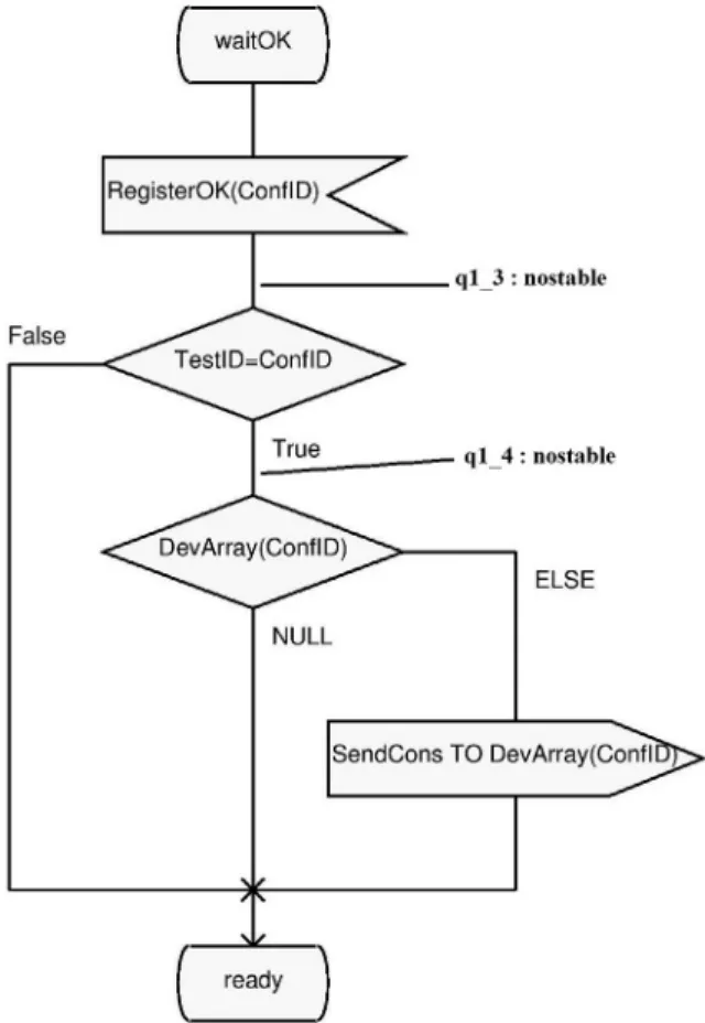
In IF, there are two types of states: "stable" and "nostable". By default, all the SDL states are translated into "stable" states. The "nostable" type is used to model supplementary states added in order to divide a long transition into small transitions. In these states, the process blocks the others and continues to execute its code until it reaches a stable state. Figure 5 shows an example of this decomposition. The transition from the state waitOK to the state ready is long. So, two "nostable" states, namely, q1_3 and q1_4, were added. Now, in each sub-transition there is only a simple set of actions (receive signal, condition test, send
signal). Generally, "nostable" states are added before every condition test.
An IF transition represents the minimal path be-tween two IF states (either stable or nostable), and contains all triggers and actions defined on that path in the same order. It has higher prior-ity than time progress; so, by default, its type is "eager". The simple input signals are direct-ly represented with an asynchronous IF input. For other types (e.g. spontaneous, continuous, priority), other auxiliary parameters are need-ed, such as PID, to translate them. For instance, the NONE signal is translated by an assigning the PID of the current process to the sender. No input part is generated in this case i.e. the input part of the corresponding IF transition is empty.
Figure 5. Nostable state example.
The SDL channels are translated using IF buf-fers. Each process has a unique input buffer through which messages are received. A buffer is defined by name, the serving discipline (i.e. queue, stack, set, and bag) and the set of signals that can be transported. The buffers are global and are used to transport signals between the
Figure 3. SDL model of HAN and its environment.
3.2. Promela Model
As mentioned before, the model is firstly trans-lated into an intermediate format IF. This sub-section explains the translation of some SDL features concerning the structure, the behavior and the data type.
IF was developed to sit between high-lev-el specification languages, such as SDL and UML, and tool specific internal representa-tions [29]. Thus, IF representarepresenta-tions can be passed between the tools, and translated into other languages, for example, SDL specifica-tions can be analyzed using SPIN as described in this paper. Another example is the UML, where the mapping is done in a way that all runtime entities (objects, call stacks, pending messages, etc.) are identifiable as a part of the IF model's state [33]. Moreover, translating high-level languages into IF may also allow extending the model with other features missed in the original language.
The structures of SDL and IF are different. In fact, an SDL model may contain blocks, pro-cesses and services. Elseways, the IF models are flat and they are composed only of process-es at one level. However, at the execution time, even an SDL model is composed of processes that react with each other. Thus, each SDL pro-cess is translated into an equivalent IF propro-cess. The remote exported/imported variables de-fined inside processes are declared only once at the IF system level. Thus, all other processes of the system can use them. Since the IF does not support the dynamic creation of process, only one instance of these processes is created. The dynamic creation will be added later, using the "run" operator in Promela.
In IF, there are two types of states: "stable" and "nostable". By default, all the SDL states are translated into "stable" states. The "nostable" type is used to model supplementary states added in order to divide a long transition into small transitions. In these states, the process blocks the others and continues to execute its code until it reaches a stable state. Figure 5 shows an example of this decomposition. The transition from the state waitOK to the state ready is long. So, two "nostable" states, namely, q1_3 and q1_4, were added. Now, in each sub-transition there is only a simple set of actions (receive signal, condition test, send
signal). Generally, "nostable" states are added before every condition test.
An IF transition represents the minimal path be-tween two IF states (either stable or nostable), and contains all triggers and actions defined on that path in the same order. It has higher prior-ity than time progress; so, by default, its type is "eager". The simple input signals are direct-ly represented with an asynchronous IF input. For other types (e.g. spontaneous, continuous, priority), other auxiliary parameters are need-ed, such as PID, to translate them. For instance, the NONE signal is translated by an assigning the PID of the current process to the sender. No input part is generated in this case i.e. the input part of the corresponding IF transition is empty.
Figure 5. Nostable state example.
The SDL channels are translated using IF buf-fers. Each process has a unique input buffer through which messages are received. A buffer is defined by name, the serving discipline (i.e. queue, stack, set, and bag) and the set of signals that can be transported. The buffers are global and are used to transport signals between the
Figure 3. SDL model of HAN and its environment.
sion of if2pml that uses additional local queues to which the saved signals are sent. In this work, this algorithm is not implemented, however, the XSpin (graphical interface for SPIN) options are used to simulate the save operator during the verification step. The "Queue" options al-low either saving the new, not used messages or discarding them. So, in this case study, the choice of saving them is adopted to simulate the SDL save operator.
While Promela has no notion of time, the new version DTPromela [27] is used in this case study to describe real-time proprieties of the HAN model. In DTPromela, a new data type called timer is introduced. It is used to declare the variables that represent discrete-time count-down timers, and then to model quantitative as-pects of SDL timers. By default, the if2pml tool translates SDL models into this language. The new definition of a timer is added to the system as a Promela macro, contained within a header file. The DTPromela model is then verified us-ing the SPIN extension: DTSPIN.
To illustrate the transformation from SDL to Promela (or DTPromela), Table 2 gives an ex-ample using the process "AMIint". An IF pro-cess with the same name as the original propro-cess was defined. It was associated with a default input queue "q_AMIint". Because the "Sender" variable is missed in IF, additional variable of type PID was defined to represent it explicitly.
4. Verification by Model Checking
The model checking is the most powerful and successful approach to verify requirements and processes. Thus, each process can specify towhich buffer a signal should be written or from which buffer a signal should be read.
On the other hand, each predefined data type used in SDL model has its equivalent in IF. The abstract data types are also translated into an IF ADT with the same signature. However, if the latter contains only predefined or implicit operators, it is translated into an enumerated type. Table 1 gives an example of the transla-tion features. For the translatransla-tion of channel C3, only the definition of one buffer is given. Nor-mally, the equivalent representation contains five buffers, because there are two processes in the block Appliance, and three processes in the block HEMS. However, for the sake of space and simplicity, only one buffer is represented. The second step is the generation of Promela model. Promela is a verification modeling lan-guage introduced by Gerard J. Holzmann [34]. The behavior of a system described in Promela is presented inside the processes. There is no notion of block, thus there is only one level, i.e. the process level. This language allows the dy-namic creation of concurrent processes to
mod-el, for example, distributed systems. Data are exchanged between processes through message channels. They can be defined to be synchro-nous (i.e., rendezvous), or asynchronous (i.e., buffered). Promela models can be analyzed with the SPIN model checker, to verify that the modeled system produces the desired behavior, as shown in the rest of this paper.
Generation of the Promela model from IF model is achieved with the if2pml tool. Thus, the Promela model is generated automatically from the IF script created earlier. However, as mentioned before, one change is made to this model. The dynamic creation of processes, us-ing the "run" operator, is added because IF does not support it. However, the if2pml has made another change. In fact, Promela lacks the pre-defined type "real". So, the tool changes all the real variables into natural variables. This modi-fication does not influence the model behavior. Indeed, the variables used (e.g. price, charge) could be either real or natural.
Another aspect missed in Promela is the save operator. This problem has been investigated by researchers in [4]. They implemented an
exten-Table 1. SDL to IF translation features example
SDL representation IF representation NEWTYPE AppType
LITERALS CTRL, CRITICAL, NULL
ENDNEWTYPE;
AppType=enum CTRL, CRITICAL, NULL;
SYNTYPE
DevPriority = Integer CONSTANTS 0:2
ENDSYNTYPE;
DevPriority = range 0..2
NEWTYPE
AppArray ARRAY(AppID, PID)
ENDNEWTYPE;
AppArray =array[0..100] of pid;
SIGNAL
PowerOFF(AppID); SIGNALPowerOFF(pid);
channel C3
from Appliance
to HEMS
with
Unregister, DeleteDev, MeteringData;
from HEMS
to Appliance
with
RegisterOK, Shutdown;
Endchannel C3;
buffer
q_SmartPlug: queue of
PowerON,
RegisterOK, DevStopped, PowerOFF, Shutdown;
state DecisionState;
input NONE; Fromdo sender DecisionState : eager := DemandResponse
Table 2. SDL to Promela translation example.
SDL representation: PROCESS AMIint (1, 1);
DCL
SumCons Consumption, HANCons Consumption := 0;
START;
NEXTSTATE ready;
STATE ready;
INPUT MeteringSum(SumCons);
TASK HANCons := SumCons;
NEXTSTATE -;
INPUT getMetering;
OUTPUT SendMetering(HANCons);
NEXTSTATE -;
ENDSTATE;
ENDPROCESS AMIint;
IF representation:
Process AMIint : buffer q_AMIint;
var
SumCons : Consumption; HANCons(0) : Consumption; Sender : pid;
state
start : init; ready;
transition from start : eager to ready;
from ready : eager
input MeteringSum(sender, SumCons) from
q_AMIint
do HANCons := SumCons
to ready;
from ready : eager
input getMetering(sender) from q_AMIint
do output SendMetering(AMIint, HANCons) to
q_UTILITYproc
to ready;
Promela representation: proctypeAMIint() {
Consumption SumCons; Consumption HANCons = 0; Byte Sender;
start:
atomic{
if
:: goto ready;
fi; } ready:
atomic{
if
:: q_AMIint?MeteringSum(sender,Sum-Cons)->
HANCons = SumCons-> goto ready;
:: q_AMIint?getMetering(sender,_)-> q_UTILITYproc!SendMetering(_ pid, HANCons)->
goto ready;
As mentioned earlier, after gaining basic con-fidence that the model has the intended propri-eties, verification was performed by generating an optimized verifier. The latter was used to exe-cute three main search modes: exhaustive verifi-cation, bitstate approximation, or hash-compact [18]-[34]. Exhaustive verification can deliver the strongest possible verification result; howev-er, the available memory in the machine did not allow completing the run because of the large state space size. Thus, the bitstate was chosen to identify correctness violations if they existed. This technique was used with the default Par-tial Order Reduction (POR) [36] to reduce the state space sufficiently. In fact, the idea behind the POR is to reduce the size of the state space that needs to be searched. It exploits the com-mutativity of concurrently executed transitions, which results in the same state when executed in different orders. This method constructs a re-duced state graph. The full state graph, which may be too big to fit in memory, is never con-structed. The implementation of this reduction method is out of the scope of this paper. Howev-er, justification of the reduction method shows that the behaviors that are not present do not add any information [36]. The hash-compact could be used if the verifier still runs out of memory before it can complete the search with bitstate exploration. This is not the case for the model. By default, XSpin searches for safety properties only (i.e. under certain conditions, something never occurs), however, when changing the tool options, liveness properties can be checked as well (i.e. under certain conditions, something will ultimately occur). The safety properties as-sert that the system always stays within some allowed region [37]. Thus, the observed behav-ior always stays within some allowed set of fi-nite behaviors in which nothing ''bad'' happens. On the other hand, liveness properties are de-fined as the set of properties the system must satisfy. So, it defines the good things that cap-ture the required functionality of a system [37]. For example, to prove the absence of assertion violations and deadlock states is a safety prop-erty; and to prove the absence of non-progress cycles is a liveness property.
This general verification was terminated without detecting any violations. Next subsection de-scribes the verification using the LTL properties.
4.2. DR Service Properties and LTL Formulas
After general verification of the model, the next step is verification of desirable properties writ-ten in LTL [38]. In LTL, the properties of a run are formalized, unambiguously and concisely, with the help of a small number of special tem-poral operators [39]-[40]-[41]. Thus, an LTL property is a temporal logic formula that de-scribes a set of infinite sequences for which it is true (e.g., a condition will eventually be true, a condition will be true until another fact be-comes true, etc).
This subsection presents some of these prop-erties in relation to the DR Service. They rep-resent requirements captured from the model specification. Nine temporal formulae were defined to help building the desired properties:
● p1 (Store >= 0) ● p2 (Battery >= 0) ● p3 (EVexist == false) ● p4 (PlugEV@ready) ● p5 (SmartPlug@ready)
● p6 (q_DemandResponse?[RTP]) ● p7 (DemandResponse@DecisionStat) ● p8 (q_DRint?[Bid])
● p9 (q_DemandResponse?[Bid] || q_UTIL-ITYproc?[AcceptBid])
Property 1: [] p1
The variable Store refers to the amount of ener-gy generated by the renewable enerener-gy sources and stored in the customer house. Several con-current processes influence this variable either by increasing or decreasing its value. This val-ue must always be positive.
Property 2: [] p2
The customer can also save energy stored in an electrical vehicle. So, same as the first property, the Battery variable, which represents the elec-trical vehicle charge, must not be negative. The first and the second properties are safety properties. They represent unwanted situations (i.e. negative value for variable) that should never occur. Furthermore, the above safety properties are of a particular kind; they are in-correctness of a system hard to build. It brings a
lot of benefits to users over other methods such as testing and simulation. In fact, testing and simulation cannot cover all the possible cas-es, scenarios and behaviors; and generally it is impossible to build the system under consider-ation to make these tests (e.g. a complex sys-tem like Smart Grid). So, these techniques are not exhaustive, and the problem or the failure cases may be among those not tested or simu-lated scenarios. Contrariwise, the model check-ing technique allows verifycheck-ing the whole sys-tem automatically. The verification terminates normally or produces a counterexample in case of failure. This counterexample details reasons why the model does not satisfy the specifica-tion. The source of errors is detected by study-ing it. The idea behind the model checkstudy-ing is to ensure that a given model satisfies enough sys-tem properties; so that a designer can increase the confidence in the correctness of the model. Once the DTPromela model was generated, the verification and validation step using DTSPIN (version 4.1.1) was used to check the correct-ness of the model. DTSPIN was installed un-der Solaris machine, with 5 GB of memory.
This verification was performed with the help of a graphical interface named XSpin (version 4.1.1) [34]. The XSpin was used, even if it is no longer supported, because it is the only graph-ical interface compatible with the DTSPIN. The interface was developed in tcl/tk. It is in-dependent from DTSPIN itself, but it executes DTSPIN command in background and provides graphical displays of the message flows, data values, and other options. Figure 6 illustrates the basic structure of SPIN (and DTSPIN as well) [34].
Given a specification written in Promela, SPIN is used, firstly to find and fix syntax errors. After that, interactive or random simulation is performed to gain the basic confidence that the model meets the intended proprieties. Then, an optimized verifier called pan [35] is generated. This verifier is compiled, with possible com-pile-time choices for the types of reduction algorithms to be used, and executed to detect counterexamples. In case the counterexamples are detected, a trail file is generated. The guid-ed simulation is then usguid-ed to detect the source of violation. The verification can be also per-formed with the linear temporal logic (LTL). Correctness claims are generated from a logic formula in order to verify specific properties of the system.
4.1. General Verification
This subsection describes "general" verifica-tion, which means launching simulations and verifications without fixing specified proper-ties to be checked. As a first step to verify the model, random simulation was launched. The latter was used to debug a model. Some assert statements (e.g. to check that a variable is nev-er taking a negative value) wnev-ere defined to be checked. It allows also tracking the channels buffer, the value of global and local variables. Other than assert statements, no correctness requirements were checked during simulation runs. All nondeterministic decisions were re-solved randomly. The simulation was repeated with different and random values of "Seed" to obtain different types of runs. The interactive simulation was not launched because the sys-tem is complex and it consists of a huge number of states.
variants. In fact, invariants are the properties given by a condition and require that this latter holds for all reachable states.
Property 3: [] <>p5
The SmartPlug process waits for the devices to be turned on. After that, it registers them in the data base. The process must not hang at the registration state for a long time because other devices may be connected to the system at this time. This property states that if p5 (i.e. SmartPlug is at the state ready) happens to be false at any given point in a run, it is always guaranteed to become true again if the run is continued.
Property 4: [] <> p4
This property is same as the previous one, but for an electrical vehicle. It ensures that PlugEV eventually always returns to the state ready. The third and fourth properties are liveness type. They define the positive behaviors indi-cating the required functionality of the system.
Property 5: [] (p3 -><> p4)
The electrical vehicle EV connected to the net-work may be unplugged by the customer at any time. The connection of EV with the network is represented by a global Boolean EVexist. The latter can be modified by several processes. It must be guaranteed that once the variable value become false, the process PlugEV stops all ac-tivities and returns to the ready state.
Property 6: [] (p6 -><> p7)
In Time-based Programs (RTP) the electricity price changes for different periods. It depends on customers' choice to decrease or change their consumption in response to price chang-es during a period. When a customer receivchang-es an RTP signal, the process DemandResponse chooses the devices to be turned off, if any, and reaches the decision state. The algorithm used in this process, and described in a previous work [3], is composed of many loops. It must be guaranteed that the process can reach the de-cision state at certain times.
Property 7: [] (p8 -><> p9)
In the Incentive-based Programs (Bid) the actions are initiated by the utility or the DR Service Provider. DR signals are sent to every customer participating in one of these
pro-grams, in order to motivate him/her to reduce their energy consumption. In exchange for this diminution, customers will benefit from an in-centive payment, bill creditor contractual ar-rangements between them and the electricity suppliers. Generally, DR signals are sent in the peak hours. They may either be voluntary demand reduction requests or mandatory com-mands. When a customer receives one of these signals, the ESI interface must either refuse the request, if the offer does not meet the user's need, or accept it and send the bid to HEMS to check the possibility of selling energy to util-ity.
The last three properties are also liveness prop-erties. However, they are of special type called response. When verifying a liveness property with DTSPIN, it is important to switch to weak fairness [42]. This means that every process that is almost always enabled should be execut-ed infinitely often. In other words, it expresses that under certain conditions, something will (or will not) occur infinitely often. DTSPIN ac-cepts only weak fairness (which is sufficient in this work).
It should be noted that XSpin generates a never claim from each property before to be verified. All the seven properties are desired, so, they are negated before generating the never claim. For instance, the last property [] (p8 -><>p9) is ne-gated and then converted to the never claim as follows:
never { /* !([] (p8 -><> p9)) */ T0_init:
if
:: (! ((p9)) && (p8)) ->goto accept_S4 :: (1) ->goto T0_init
fi; accept_S4: if
:: (! ((p9))) ->goto accept_S4 fi;
}
The result of the verification has showed that the model is too complex. In fact, this is clear from Table 3, which shows the number of states searched while verifying the properties. It presents the states stored (i.e. total num-ber of unique global system states stored in the state space), and states matched (i.e. how
many times the search returns to a previously visited state in the search tree).
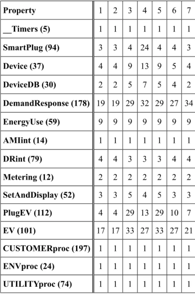
During the verification, DTSPIN detected un-reached states in the processes, as shown in Table 4. For each process, the number of un-reached states is indicated between brackets. Generally, in a full state space search, the un-reached states indicate a dead code (i.e. tran-sitions are unreachable). However, this is not the case here. In fact, the search depth was set to 10000, which was imposed by the available memory in the operating system (i.e. 5 GB). If a higher value was used, pan verifier got out of the memory. Despite not detecting any viola-tion, this is a limitation of this verification. Verification with DTSPIN took several hours to complete, when all available memory was used. This problem is due to dynamic creation of processes. In fact, each time a device is off, it can be turned on by the user. Thus, a new process with new PID is created. In order to fix this, the number of "PowerOFF" signal sent in the system was limited. The same thing was done with the EV, so only one vehicle was plugged at a time. This ensures that the pro-cesses will be created and ended only once. It is important to note here that, unlike SDL, Promela distinguishes between the termina-tion of process and the end of its executermina-tion. A process terminates (i.e. releases the resourc-es allocated to it) when all younger procresourc-essresourc-es have terminated first. It is impossible to force a process to terminate because it depends on other processes. However, in this verification, the process was forced to end by making it
reach the end bracket (i.e. goto LABEL). The process may be not terminating, but it no lon-ger has any interaction with others.
After the modification, verification was run again, with a search depth of 1000000. This time it finished in six hours (in average) with-out detecting any violations, but the pan was again out of the memory. Thus, to be sure that the model is free of errors, the stack cycling method [34] is enabled. This method is useful for verifications that require a very large depth limit, which is the case in this work. When the stack cycling is enabled, only a small fraction of the stack is kept in the memory, while the unused portions of the search stack are stored on the disk. With this method, the pan did not run out of memory. When this option was used with the first LTL property, the verification took more than 48 hours, without detecting any vi-olation. The problem of the verification time is due to the process termination as mentioned before.
Table 4. Unreached states.
Property 1 2 3 4 5 6 7
__Timers (5) 1 1 1 1 1 1 1
SmartPlug (94) 3 3 4 24 4 4 3
Device (37) 4 4 9 13 9 5 4
DeviceDB (30) 2 2 5 7 5 4 2
DemandResponse (178) 19 19 29 32 29 27 34
EnergyUse (59) 9 9 9 9 9 9 9
AMIint (14) 1 1 1 1 1 1 1
DRint (79) 4 4 3 3 3 4 4
Metering (12) 2 2 2 2 2 2 2
SetAndDisplay (52) 3 3 5 4 5 3 3
PlugEV (112) 4 4 29 13 29 10 7
EV (101) 17 17 33 27 33 27 21
CUSTOMERproc (197) 1 1 1 1 1 1 1
ENVproc (24) 1 1 1 1 1 1 1
UTILITYproc (74) 1 1 1 1 1 1 1
Table 3. Number of states explored by DTSPIN.
Property States stored States matched
1 4.84004e+07 4.39905e+08
2 4.84004e+07 4.39905e+08
3 4.82335e+07 3.60119e+08
4 4.81368e+07 3.53796e+08
5 4.82335e+07 3.60119e+08
6 4.83146e+07 4.4187e+08
![Figure 1. A structural vision of an SDL model [10].](https://thumb-us.123doks.com/thumbv2/123dok_us/8037218.2128198/3.1785.270.1524.294.787/figure-structural-vision-sdl-model.webp)


![Figure 6. The structure of SPIN [34].](https://thumb-us.123doks.com/thumbv2/123dok_us/8037218.2128198/10.1785.201.844.1393.2251/figure-the-structure-of-spin.webp)