International Journal of Research in Engineering & Applied Sciences
Email:- editorijrim@gmail.com, http://www.euroasiapub.org
50
EXPERIMENTAL INVESTIGATION ON TWO-STROKE S.I ENGINE WITHCATALYTIC
(COPPER) COATED PISTON USING GASOLINE-BUTANOL BLENDS
Dr.M.Harinath Reddy1, Professor
Department of mechanical engineering,
Gurunanak institutions technical campus, Hyderabad, India
R.Hussain Vali2, . Assistant Professor,
Gurunanak institutions technical campus, Hyderabad, India
P.Yagnasri3 Assistant Professor,
Gurunanak institutions technical campus, Hyderabad, India.
ABSTRACT
The thermal efficiency of most commercially used engines ranges from 38% to 42%, as nearly 58% to 62% of energy is lost in the form of waste heat. In order to save energy the hot parts are coated. This will lead to reduction in heat transfer through the engine, involving an increased efficiency. Change in combustion process due to insulation also affects emissions. Hence, In this work an effort made to study the effect of the piston top coated with catalytic materials such as copper using plasma spray gun. The concept of catalytic combustion in spark ignition engines has been tried by various researches which offers improved thermal efficiency and reduced exhaust emissions due to oxidation of fuels with aid of catalyst. The performance and emission characteristics of the engine coated with catalytic materials are studied and are compared with the standard engine. Experimental investigations are conducted to evaluate the performance and Measure the exhaust emissions from two-stroke, single cylinder, spark ignition (SI) engine, with Butanol & Gasoline Blends (90% Gasoline and 10% Butanol by volume, 80% Gasoline and 20% Butanol by volume, 70% Gasoline and 30% Butanol by volume) having Copper coated Piston Crown of thickness 300 μ and compared with conventional SI engine with pure gasoline operation. Performance parameters such as Brake thermal efficiency, Brake specific fuel consumption ,Mechanical efficiency are determined and exhaust emissions like carbon monoxide (CO) and un-burnt hydro carbons (UBHC) are Measured by applying different loads on the engine. Copper coated piston crown with Butanol blended gasoline engine has improved performance and reduced pollutants as compared with conventional engine.
Keywords: Butanol, S.I Engine, BSFC, copper coated combustion chamber, Butanol-Gasoline blends, CO and UBHC.
INTRODUCTION
International Journal of Research in Engineering & Applied Sciences
Email:- editorijrim@gmail.com, http://www.euroasiapub.org
51
(CO) and un-burnt hydrocarbons (UBHC) formed due to incomplete combustion which leads to scavenging. The Engine modification with copper coating on piston crown improves engine performance as copper acts as a good catalyst for combustion reaction and hence ensures complete combustion and higher operating temperatures. Agricultural and transport sectors are almost Petroleum fuel dependent whose resources are depleting day-by-day. The transport sector remains to be the most problematic sector as no alternative to petroleum based fuel has been successful so far. Research and development throughout the world for an effective alternate to fossil fuels has continuously persisted and the usage of alcohols to be the best solution. In order to save our planet earth from undesirable effects, it is necessary to go for cleaner fuels. From previous experiments, it is evident that there are various problems observed with alternative fuels for engines due to its physical properties like high viscosity, problem in pumping, combustion and atomization. For two stroke engines the emissions and scavenging is the major defect. It is overcome with the help of using thermal barrier coatings on piston crown. Due to this thermal efficiency may enhance and good scavenging may possible. So for in this project copper metal coating on piston crown is used along with butanol as an alternative fuel in the form of blends B 10,B 20, B 30. A two strokes; single cylinder SI engine was used for conducting this study. Performance tests were conducted for fuel consumption, volumetric efficiency, brake thermal efficiency, brake power, engine torque and brake specific fuel consumption, using unleaded gasoline and additives blends with different percentages of fuel at varying engine torque condition and constant engine speed .The result showed that blending unleaded gasoline with additives increases the brake power, volumetric and brake thermal efficiencies and fuel consumption addition of 5% iso butanol and 10% ethanol to gasoline gave the best results for all measured parameters at all engine torque values . In this paper we studied the effect of butanol –gasoline blends on copper coated engine.MATERIALS AND METHODS
Copper Coating:
The present work focuses on the study of copper coating deposition as the main coat on metallic substrate without any intermediate bond coat. Aluminum alloy chosen as the substrate material and the deposition of copper is made by atmospheric plasma spray coating route. The basic aim has been to study the formation of copper and effect on engine parameters. This coating possesses desirable coating characteristics such as good adhesion strength, hardness and reasonable porosity, High-temperature oxidation resistant, High-temperature corrosion resistant and microstructure etc.
International Journal of Research in Engineering & Applied Sciences
Email:- editorijrim@gmail.com, http://www.euroasiapub.org
52
THE PLASMA SPRAYING PROCESS:The Plasma Jet:
Plasma Spraying, first conducted by Reinecke in 1939, was advanced in the late 50´s by several other scientists. Since then, it has become increasingly sophisticated and is now a days widely used in surface technology. The plasma spraying gun consists principally of two electrodes.
Fig 1. Schematic diagram of Plasma spray gun Properties Variation
Fuel consumption Decrease
Engine lifetime Increase
Engine power Increase
Emission Decrease
Oil consumption Decrease
Reliability Increase
Components temperature
Decrease
Valves lifetime Increase
Costs Decrease
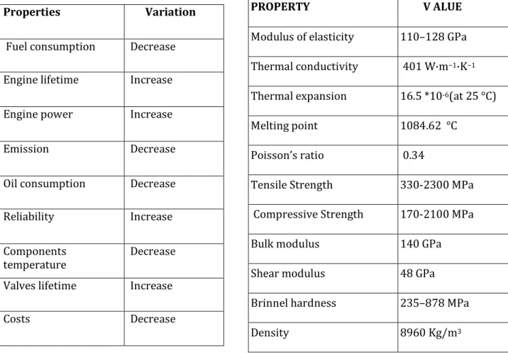
PROPERTY V ALUE
Modulus of elasticity 110–128 GPa
Thermal conductivity 401 W·m−1·K−1
Thermal expansion 16.5 *10-6(at 25 °C)
Melting point 1084.62 °C
Poisson’s ratio 0.34
Tensile Strength 330-2300 MPa
Compressive Strength 170-2100 MPa
Bulk modulus 140 GPa
Shear modulus 48 GPa
Brinnel hardness 235–878 MPa
International Journal of Research in Engineering & Applied Sciences
Email:- editorijrim@gmail.com, http://www.euroasiapub.org
53
Figure 1. shows a schematic of the plasma spray gun, with the thoriated tungsten cathode inside the water-cooled copper anode. A gas, commonly a mixture of argon and hydrogen, is injected into the annular space between the two. To start the process, a DC electric arc is stuck between the two electrodes. The electric arc produces gas ionization, i.e. gas atoms lose electrons and become positive ions. Electrons move with high velocity to the anode, while ions move to the cathode. On their way, electrons and atoms collide with neutral gas atoms and molecules. Hence, the electric arc continuously converts the gas into a plasma (a mixture of ions and electron of high energy). The plasma is on average, electrically neutral and characterized by a very high temperature. The kinetic energy of the plasma (mostly carried by free electrons) is converted into thermal energy during collisions between ions, electrons and atoms. In this way, the plasma is capable of producing temperatures up to approximately 104K. The hot gas exits the nozzle of the gun with high velocity. Powder material is fed into the plasma plume. The powder particles are melted and propelled by the hot gas onto the surface of the substrate. When individual molten particles hit the substrate surface, they form splats by spreading, cooling and solidifying. These splats then incrementally build the coating. Plasma plumes exhibit radial temperature gradients. Whereas particles that pass through the central core of the plasma tend to be melted, superheated or even vaporized, particles that flow near the periphery may not melt at all. This will affect the final structure of the coating, which may contain partially molten or un melted particles. Voids, oxidized particles and un melted particles can appear in the coating . These effects may be desirable, or they may be unwanted, depending on the requirements of the coating.Fig 2. Piston before Coating Fig 3. Piston after Coating
Butanol in Internal Combustion Engines
International Journal of Research in Engineering & Applied Sciences
Email:- editorijrim@gmail.com, http://www.euroasiapub.org
54
having a positive effect on vehicle emissions. However, there are several drawbacks to ethanol. While ethanol is soluble in gasoline, additives are required to ensure its solubility in diesel fuel especially at lower temperatures and addition of ethanol to diesel fuel can reduce lubricity leading to wear problems in fuel pumps. Due to the lower cetane number of ethanol, cetane enhancing additives are usually required to improve ignition delay and reduce cyclic irregularities. Perhaps most important of all is that ethanol has a much lower flash point than diesel fuel and higher vapour formation potential which can lead to safety issues in confined spaces. Butanol is a viable alternative to ethanol and offers several benefits over ethanol. Ethanol is fully miscible in water and thus cannot be transported using existing fuel supply pipelines.Whereas butanol is less corrosive than ethanol and is less prone to water contamination allowing it to be transported using existing fuel supply pipelines. Moreover, butanol has a heating value of 36.4 MJ/kg compared to 24.8 MJ/kg for ethanol which is much closer to the 44.9 MJ/kg of gasoline. This, combined with the higher stoichiometric air-fuel ratio, allow higher blending levels of butanol in gasoline than ethanol without changing regulations, engine control systems, and distribution networks. Additionally, butanol has a lower latent heat of vaporization than ethanol which could reduce issues with fuel atomization and combustion during cold start conditions typical of alcohol fuels. Butanol also offers benefits over ethanol for use in CI engines including a higher cetane number, lower vapor pressure, and improved miscibility in diesel fuel.
BLEND DENSITY IN (kg/m3) CALORIFIC VALUE (MJ/kg)
B 10 748 39.12
B 20 751 38.35
B 30 758 37.22
EXPERIMENTAL SETUP
For the present investigation, an experimental set up is installed on TVS SUZUKI MAX-100 A TWO STROKE PETROL ENGINE with the necessary instrumentation to measure performance and emissions at different operating conditions .The details of the experimental set up are presented in this chapter. A schematic of experimental set up is
Shown in figure 4 . .
International Journal of Research in Engineering & Applied Sciences
Email:- editorijrim@gmail.com, http://www.euroasiapub.org
55
Technical Specifications of the EngineTYPE MOTORCYCLE
Engine type 2 stroke, air cooled
Engine starting Kick start
Maximum power 7.8 bhp@5500 rpm
Maximum torque 9.8 Nm@5000 rpm
transmission 4 speed
Top speed 85 kmph
Engine displacement 98 cc
No of cylinders 1
valves for cylinder 0
bore 50 mm
stroke 50 mm
Fuel type petrol
Fuel capacity 14 liters
Final drive(rear wheel) chain
Compression 6.7:1
Table No. 5.1 Technical Specifications
RESULTS AND DISCUSSIONS
BRAKE THERMAL EFFICIENCY
Fig 6 represents the variation of brake thermal efficiency for conventional engine. From this graph it is clear that the blend B 10 has better brake thermal efficiency when compared to gasoline and other blends like B 20 and B 30.
International Journal of Research in Engineering & Applied Sciences
Email:- editorijrim@gmail.com, http://www.euroasiapub.org
56
Fig6 conventional engineFig 7 coated engine BRAKESPECIFIC FUEL CONSUMPTION (BSFC)
Following two figures represent the brake specific fuel consumption curves for conventional and copper coated engines.
Fig 8 represents the variation of brake specific fuel consumption (BSFC) of the conventional engine, from this graph it is clear that for the blend B 10, the brake specific fuel consumption is lower as compared to gasoline and other blends like B 20 and B 30, the brake specific fuel consumption is almost same for all blends up to 70% of the load.
From fig 9, it is clear that the brake specific fuel consumption (BSFC) is high at low brake power and it is decreasing when the brake power increases. The trend is similar in the case of coated and uncoated piston. The reduction of brake specific fuel consumption is 0.106 Kg/KW-hr at full load condition for coated piston.
0 5 10 15 20 25 30
0 0.417 0.759 1.046 1.325
B R A K E T H E R M A L E F ICIE N C Y (% ) BRAKE POWER(KW) B 20 GASOLINE B 10 B 30 0 5 10 15 20 25 30 35
0 0.407 0.749 1.036 1.325
B R A K E TH ER M A L EF F IC IEN C Y (% ) BRAKE POWER(KW)
COT B 10
COATED GASOLINE
NORB10
COATED B 20
International Journal of Research in Engineering & Applied Sciences
Email:- editorijrim@gmail.com, http://www.euroasiapub.org
57
Fig8 conventional engineFig9 coated engine MECHANICAL EFFICIENCY
Above two figures represent the variation of mechanical efficiency for conventional and coated engine.
Fig 10 represents the variation of mechanical efficiency for conventional engine; from this graph it is clear that the mechanical efficiency for B 10 blend is higher than gasoline and other blends B 20 and B 30, due to higher brake power in that case.
From fig 11, it observed that the mechanical efficiency is increasing for the coated piston from low load conditions to a higher load conditions. The efficiency is 3.39 % higher in coated piston engine as compared to conventional engine
0 2 4 6 8 10
0.407 0.749 1.036 1.325
B R A K E S P EC IF IC F U EL C O N S U M P TI O N (K g/ K Wh )*10 BRAKE POWER(KW) GASOLINE B 10 B 20 B30 0 2 4 6 8 10
0 0.407 0.749 1.036 1.325
B R A K E S P EC IF IC F U EL C O N S U M P TI O N (K g/ K Wh )*10 BRAKE POWER(KW)
COA B 10
NOR B 10
COA GASOLINE
COA B 20
International Journal of Research in Engineering & Applied Sciences
Email:- editorijrim@gmail.com, http://www.euroasiapub.org
58
Fig10 conventional engineFig11 coated engine UNBURNT HYDRO CARBON (UBHC)
Above two figures represents the variation of un burnt hydro carbon (UBHC) for different blends at different brake powers for conventional and coated engine.
Fig 12 represents the variation of un burnt hydro carbon (UBHC) for conventional engine with brake power for different blends of butanol. From this graph the HC emissions are observed to be lower for the blend B 10 as compared to other blends and gasoline up to 60% of load.
From fig 13 the measured HC emissions are observed to be reduced when the engine running with coated piston, because coating ensures complete combustion due to its high temperatures. As a result HC will split into hydrogen and carbon, which mixes with oxygen, thereby reducing HC emissions. The variation of HC at no load is about 600 ppm and at full load it is about 115 ppm (23.72% by vol).
0 5 10 15 20 25 30 35
0 0.407 0.749 1.036 1.325
M
EC
H
A
N
IC
A
L
EF
F
IC
IEN
C
Y
(%
)
BRAKE POWER(KW)
B 10
GASOLINE
B 20
B 30
0 5 10 15 20 25 30 35 40
0 0.407 0.749 1.036 1.325
M
EC
H
A
N
IC
A
L
EF
F
IC
IEN
C
Y
(%
)
BRAKE POWER(KW)
COA B10
NOR B 10
COA GASOLINE
COA B 20
International Journal of Research in Engineering & Applied Sciences
Email:- editorijrim@gmail.com, http://www.euroasiapub.org
59
Fig12 conventional engineFig13 coated engine CARBONMONOXIDE (CO)
Above two figures represent the variation of Carbon monoxide for different blends of conventional and coated engine.
Fig 14 represents the variation of CO emissions of conventional engine; from this graph it is clear that the CO emissions are lower for blend B 10 up to 60% of load. The CO emissions for blends B 20, B 30 are found to be slightly higher.
Fig 15 shows the emissions of CO for different blends at different loads. It is found that the CO emissions are decreased in the case of coated piston due to complete combustion. At high temperatures carbon easily combines with oxygen and reduces CO emissions. At no load CO emissions are 23.72 %( by volume) less in case of coated piston compared to that of uncoated piston. 0 500 1000 1500 2000 2500 3000
0 0.407 0.749 1.036 1.325
U N B U R N T H Y D R O C A R B O N (p p m )
BRAKE POWER(KW)
GASOLINE B 10 B20 B 30 0 500 1000 1500 2000 2500 3000 3500
0 0.407 0.749 1 1.325
U N B U R N T H Y D R O C A R B O N (p p m ) BRAKE POWER(KW)
COA B 10
NOR B 10
COA GASOLINE
COA B 20
International Journal of Research in Engineering & Applied Sciences
Email:- editorijrim@gmail.com, http://www.euroasiapub.org
60
Fig14 conventional engineFig15 coated engine
CONCLUSION
Copper acts as a barrier for the heat transfer to the surroundings from the engine combustion chamber and reduces the heat loss from the engine. Therefore the efficiencies are increased and the emissions are reduced because of various chemical reactions takes place inside the cylinder at high temperature. Brake thermal efficiency and mechanical efficiency of coated piston are increased by the average value of 1.16% and 3.39% respectively. 3.66% reduction in total fuel consumption and 3.594% reduction in specific fuel consumption were achieved with the coated piston. 23.72% of unburned HC emissions were reduced by using the coated piston. CO emissions are reduced by 39.21% at initial conditions because of at high temperature C easily combines with O2 and reduces CO emission.
0 0.1 0.2 0.3 0.4 0.5
0 0.407 0.749 1.036 1.325
C
O
(%
V
O
L)
BRAKE POWER(KW)
GASOLINE
B10
B20
B30
0 0.05 0.1 0.15 0.2 0.25 0.3 0.35 0.4 0.45
0 0.407 0.749 1.036 1.325
C
O
(%
V
O
L)
BRAKE POWER(KW)
COA B 10
NOR B10
COA GASOLINE
COA B 20
International Journal of Research in Engineering & Applied Sciences
Email:- editorijrim@gmail.com, http://www.euroasiapub.org
61
From the results of the study, the following conclusions can be deduced:1. Using butanol as a fuel additive to unleaded gasoline causes an improvement in engine performance.
2. The blends of butanol (B 10) gives lower specific fuel consumption than the gasoline at full loads when operating on copper coated piston.
3. Brake Thermal efficiency of the tested Gasoline engine is improved when it is fuelled with Butanol-Gasoline blends operating on Copper coated piston.
4. Mechanical efficiency is higher for B 10 compared to gasoline fuel operation is observed. 5. Unburnt HC emissions and CO emissions are reduced due to complete combustion
Inside the combustion chamber.
From the above analysis the main conclusion is the Butanol and its Gasoline blends are suitable substitute for Gasoline as they produce lesser emissions than pure gasoline on the copper coated engines.
REFERENCES
1. T.Karthikeya Sharma “Performance and emission characteristics of the thermal barrier coated SI engine by adding argon inert gas to intake mixture”Journal of Advanced Research (2014).
2. D.BALAJI" influence of isobutanol blend in spark ignition engine performance operated with gasoline and ethanol "Vol .2)7(, 2859-2868 ( 2010).
3. T.O. Wagner, D.S. Gray, B.Y. Zarah, A.A. Kozinski, Practicality of alcohols as motor fuel, SAETechnical Paper 790429 (1979) 1591–1607.
4. Imdat Taymaz“The effect of thermal barrier coating on the diesel engine performance”. 5. Alvydas Pikunas, Saugirdas Pukalskas & Juozas Grabys" influence of composition of gasoline
– ethanol blends on parameters of internal combustion engines"Journal of KONES Internal Combustion Engines vol.10, 3-4 (2003).
6. M .Al-Hasan "Effect of ethanol–unleaded gasoline blends on engine performance and exhaust emission"Energy Conversion and Management 44, 1547–1561 (2003).
7. M .Abu-Zaid, O .Badran, and J .Yamin" effect of methanol addition to gasoline on the performance of spark ignition engines "Energy & Fuels 18, pp(312-315), (2004).
8. M.V .Mallikarjun1 and Venkata Ramesh Mamilla2" Experimental Study of Exhaust Emissions &Performance Analysis of Multi Cylinder S.I.Engine When Methanol Used as an Additive" Volume 1 Number 3, pp .201–212 (2009).
9. Szwaja and Naber, Alasfour“ Combustion of n-butanol in a spark-ignition IC engine”.