Doctoral Thesis
Numerical Modelling and In-Process Expert System for
the Assessment of Large Scale Seals
Ismail Abubakar Jimoh
A thesis submitted to the University of Bolton in partial fulfilment of
the requirements for the degree of Doctor of Philosophy
KEYWORDS:
Artificial Intelligence Technique, Condition Monitoring, Correlation, Direct/Indirect
Sensor, Elastomer, Elastomeric Seal, Experimental Benchmarking, Expert System,
Finite Element Analysis, Fuzzy Logic, Hyperelasticity, Knowledge Base, Mechanical
Education is the most powerful weapon which you can use to change the world
-Nelson Mandela
If I have seen further than others, it is by standing upon the shoulders of giants
-Isaac Newton
Genius is 1% talent and 99% percent hard work...
-Albert Einstein
As complexity rises, precise statements lose meaning and meaningful statements lose precision
i
Copyright
Attention is drawn to the fact that copyright of this thesis rests with its author. This copy of the
thesis has been supplied on the condition that anyone who consults it is understood to
recognise that its copyright rests with the author and that no quotation from the thesis and no
information derived from it may be published without the prior consent of the author.
This thesis may be made available for consultation within the University Library and may be
photocopied or lent to other universities in accordance with academic rules and ethical conduct
ii
Declaration
I hereby declare that all information in this document has been obtained and presented in
accordance with academic rules and ethical conduct. No work in this thesis has been
previously submitted for a degree at any other university.
I also declare that all sources of information that are not original to this work have been duly
acknowledged.
iii
Acknowledgment
There are many people that I would like to acknowledge who have helped me throughout the
long period to make this work a reality.
Firstly my profound gratitude goes to my family whose encouragement and support has today
made this work a reality. In particular, I wish to register my sincere appreciation and gratitude
to my father Abubakar Jimoh for his awesome contribution that has helped me to actualise my
dream.
Secondly, I would like to thank my supervisors Prof. Peter Myler and Dr. Erping Zhou for their
untiring positive contribution throughout this research despite tight academic schedule, without
their support and exemplary knowledge of the subject; I will not have been able to complete
this work. I have achieved a respectable academic position which wouldn’t have been possible
without their mentoring.
Thirdly, my appreciation goes to Andy Parkinson of James Walker limited, UK, for supplying
test materials needed for the project, and also the technical team of the company for their
valuable industrial information and support.
I will not end this acknowledgment without giving due regard to my friends and colleagues for
iv
Abstract
The design and development of large scale seals, under a variety of loads and how they can
be monitored for fault diagnosis and life prediction, have been investigated in this study. The
work builds upon ideas of developing a physically based mathematical model of an
elastomeric lip seal. The approach utilised finite element analysis to simulate its in-service
operating condition, in order to obtain parameters needed to be considered for credible life
performance of such seal, and therefore allow an extension for new large scale problems, in
which the application can be used under increased loads.
Accurate modelling requires the knowledge of the boundary condition, material properties and
some real life data, which are key parameters to developing a reliable optimised model and a
system to enable condition monitoring of seal. The material properties of an elastomer,
subjected to tension and compression loads are obtained in this work, whilst putting into
consideration the large strain nonlinear elasticity exhibited by the materials. Hyperelastic
material models were utilised, since they put into consideration material nonlinearity of
elastomers. This eliminates the shortcomings of the conventional Hookean material law
currently used in the industries for seal design study.
Considering the potential for the demand of a seal monitoring and diagnostic system in the
future, this thesis introduces a new, in-process cognitive expert system structure. The
structure consists of a knowledge base and an inference model, that is able to evaluate the
fault severity of a seal system based on the knowledge provided to it. A case study herein
reveals that the structure is able to retain control rules taught to it for the assessment of a
sealing process. A computer simulation has been used to analyse, illustrate and evaluate the
reliability of the structure, and it shows that it can play a key role in successful application of
v
Table of Contents
Copyright ... i
Declaration ...ii
Acknowledgement ... iii
Abstract ... iv
Table of Contents ... v
List of Figures ... xi
List of Tables ... xvii
Nomenclature ... xviii
Published Work ... xxi
Chapter 1 1.0 Introduction ... 1
1.1 Background ... 1
1.2 Rotary Lip Seal ... 2
1.3 Rotary Lip Seal Damage and Seal Failure ... 4
1.4 Research Aim ... 5
1.5 Research Objectives ... 5
1.6 Contribution to Knowledge of the Thesis ... 6
1.7 Thesis Structure ... 6
Chapter 2 2.0 Literature Review ... 9
vi
2.2 Rotary Seal Profile Description ... 12
2.3 Numerical Modelling in Lip Seal Design Study ... 15
2.4 Effect of Shaft Surface on Lip Seal ... 19
2.5 Lip Seal Material ... 25
2.6 Conclusion ... 27
Chapter 3 3.0 Finite Element Modelling ... 29
3.1 Introduction ... 29
3.2 Abaqus ... 30
3.3 FEA Solution Process ... 30
3.3.1 Pre-Processing ... 31
3.3.2 Solving ... 31
3.3.3 Post-Processing ... 32
3.4 FEA Solution Integration Scheme ... 32
3.4.1 Implicit Scheme ... 33
3.4.2 Explicit Scheme ... 34
3.5 Finite Elements ... 34
3.6 Specialist Material Behaviour ... 35
3.7 Finite Element Formulation for Elastomers ... 35
3.8 Material Laws for Hyperelastic (Elastomeric) Materials ... 36
3.8.1 Hyperelastic Constitutive models ... 39
3.9 Discussion ... 41
vii Chapter 4
4.0 Experimental Analysis and Material Evaluation for Seal Design ... 44
4.1 Introduction ... 44
4.2 Experimental Test for Mechanical Properties ... 44
4.2.1 Tensile Test Result ... 47
4.2.2 Compression Test Result ... 56
4.3 Material Model Validation ... 65
4.3.1 Analytical Validation of Hyperelastice Model in Tension ... 66
4.3.2 Analytical Validation of Hyperelastice Model in Compression ... 67
4.4 NBR Thermal Property Test ... 70
4.4.1 Coefficient of Thermal Expansion ... 70
4.4.2 Result ... 73
4.5 Conclusion ... 73
Chapter 5 5.0 Lip Seal Finite Element Modelling and Numerical study ... 75
5.1 Introduction ... 75
5.2 Seal Geometry Measurement ... 76
5.2.1 Seal Cross-Sectional Geometry ... 77
5.3 Seal Load Analysis ... 78
5.3.1 Simulation Predicted Results ... 80
5.3.2 Seal Geometry Modification ... 83
5.4 Contact Problem Description ... 92
viii
5.4.2 Simulation Predicted Results ... 96
5.5 Effect of High Temperature on Seals ... 97
5.5.1 Lip Seal Thermal Studies ... 97
5.5.2 Simulation Predicted Results ... 100
5.6 Conclusion ... 103
Chapter 6 6.0 Experiment and Data Correlation Analysis ... 105
6.1 Introduction ... 105
6.2 Rotary Screening Test Rigs Description ... 106
6.3 Data Analysis... 109
6.3.1 Matlab ... 110
6.3.2 Obtaining Test Variables ... 110
6.4 Correlating Seal Operating Parameters ... 118
6.4.1 Correlation ... 118
6.4.2 Cross Correlation ... 120
6.5 Conclusion ... 125
Chapter 7 7.0 Condition Monitoring and fault Diagnosis of Seals ... 127
7.1 Introduction ... 127
7.2 Mechanical Face Seal Monitoring Technique... 127
7.2.1 Acoustic Emission Monitoring Technique ... 129
7.2.2 Ultrasonic Shear Sensor Monitoring Technique ... 130
ix
7.4 Multi-sensor and Multi-parameter Based Monitoring ... 132
7.5 Direct and Indirect Sensor Measurement ... 133
7.6 Conclusion ... 134
Chapter 8 8.0 Expert System ... 136
8.1 Introduction ... 136
8.2 Overview of Expert System ... 137
8.3 Seal Fault Diagnosis ... 138
8.4 Fuzzy Logic ... 140
8.5 Fuzzy Logic Control ... 141
8.6 Review of Fuzzy Operation ... 142
8.6.1 Fuzzification ... 142
8.6.2 Membership Function ... 142
8.6.3 Linguistic Rules ... 145
8.6.4 Defuzzification ... 146
8.7 Seal Operational Window ... 147
8.8 An Expert System Structure for Seal Assessment ... 149
8.8.1 Knowledge Base/Knowledge Acquisition ... 150
8.8.2 logical Inference System ... 151
8.8.3 Decision/Output ... 151
8.9 Limitation of Intelligent Technique ... 151
x Chapter 9
9.0 Development Expert System for Seal Monitoring and Life Prediction ... 153
9.1 Introduction ... 153
9.2 Development of Condtion Monitor Prototype ... 154
9.3 Case Study ... 160
9.3.1 Input and Output Parameters ... 164
9.4 Discussion ... 172
9.5 Conclusion ... 173
Chapter 10 10.0 Conclusion and Recommendation ... 175
10.1 Conclusion ... 175
10.2 Observation from the Research ... 179
10.3 Recommendation for Future Work ... 179
References ... 181
xi
List of Figures
Fig 1.1 Fluid leakage in a steam turbine feed pump ... 1
Fig 1.2 Cut-section of a rotary lip seal running on shaft ... 3
Fig 1.3 Axisymmetric section of a rotary lip seal running on shaft ... 3
Fig 2.1 Micro-asperities on elastomeric lip seal ... 10
Fig 2.2 Hydrodynamic pumping action of a rotary seal ... 11
Fig 2.3 Orientation of asperities during shaft rotation ... 12
Fig 2.4 Dependence of seal lip contact force on its length ... 13
Fig 2.5 Rotary seal geometry ... 14
Fig 2.6 Experiment vs. FEA result on the effect of contact force ... 17
Fig 2.7 Mechanical vs. thermal-mechanical analysis on the contact force ... 17
Fig 2.8 FEA showing high stress around the contact region ... 18
Fig 2.9 Air side contact pressure for different shaft sizes ... 19
Fig 2.10 Schematic of sealing zone ... 19
Fig 2.11 Schematic of structured shafts ... 21
Fig 2.12 Measurement of pumping rate ... 22
Fig 2.13 Pumping rate vs. shaft parameters ... 23
Fig 2.14 Shaft surface topography ... 24
Fig 2.15 Pumping rate of shaft for different manufacturing methods ... 25
Fig 2.16 Nonlinear elastic behaviour vs. linear elastic behaviour ... 26
Fig 3.1 Physical model (A) and finite element mesh (B) of a tube ... 30
Fig 3.2 FEA simulation process ... 31
xii
Fig 3.4 Element under hydrostatic pressure ... 36
Fig 3.5 Pure homogenous strain (A) unstrained state (B) strained state ... 37
Fig 3.6 Nonlinear behaviour of rubber ... 38
Fig 4.1 Tensile test specimen ... 45
Fig 4.2 Compression test specimen ... 46
Fig 4.3 Experimental setup for tensile test ... 46
Fig 4.4 Experimental setup for compression test ... 47
Fig 4.5 Stress-strain curve of NBR test specimen at 155% tensile strain ... 48
Fig 4.6 Tensile test curve vs. evaluated Mooney-Rivlin model ... 48
Fig 4.7 Tensile test curve vs. evaluated Polynomial N2 model ... 49
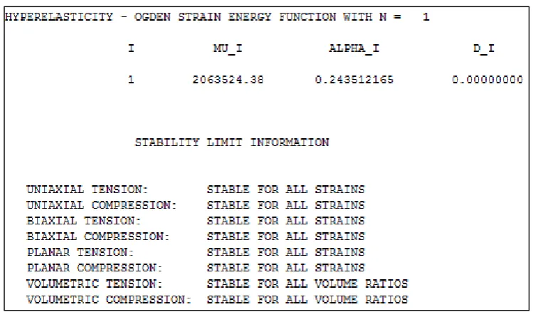
Fig 4.8 Tensile test curve vs. evaluated Ogden N1 model ... 49
Fig 4.9 Tensile test curve vs. evaluated Neo-Hooke model ... 50
Fig 4.10 Tensile test curve vs. evaluated Yeoh model ... 50
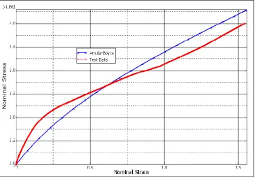
Fig 4.11 Tensile test curve vs. evaluated Arruda-Boyce model ... 51
Fig 4.12 Evaluated tensile test data for stability check; Mooney-Rivlin model ... 51
Fig 4.13 Evaluated tensile test data for stability check; Polynomial-N2 model ... 52
Fig 4.14 Evaluated tensile test data for stability check; Ogden model ... 52
Fig 4.15 Evaluated tensile test data for stability check; Neo-Hooke model ... 53
Fig 4.16 Evaluated tensile test data for stability check; Yeoh model ... 53
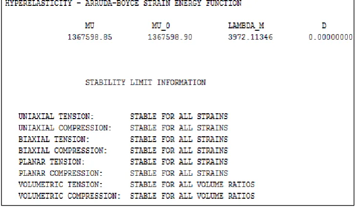
Fig 4.17 Evaluated tensile test data for stability check; Arruda-Boyce model ... 54
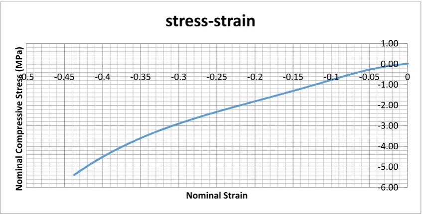
Fig 4.18 Stress-strain curve of constrained NBR test specimen in compression ... 57
Fig 4.19 Stress-strain curve of unconstrained NBR test specimen in compression ... 57
xiii
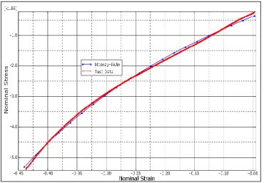
Fig 4.21 Compression test curve vs. evaluated Mooney-Rivlin model ... 58
Fig 4.22 Compression test curve vs. evaluated Neo-Hooke model ... 59
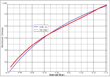
Fig 4.23 Compression test curve vs. evaluated Ogden model ... 59
Fig 4.24 Compression test curve vs. evaluated Polynomial N2 model ... 60
Fig 4.25 Compression test curve vs. evaluated Van-Der-Waals model ... 60
Fig 4.26 Compression test curve vs. evaluated Yeoh model ... 61
Fig 4.27 Evaluated compression test data for stability check; Mooney-Rivlin model .. 61
Fig 4.28 Evaluated compression test data for stability check; Polynomial N2 model .. 62
Fig 4.29 Evaluated compression test data for stability check; Ogden model ... 62
Fig 4.30 Evaluated compression test data for stability check; Neo-Hooke model ... 63
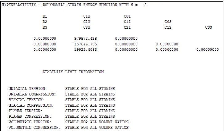
Fig 4.31 Evaluated compression test data for stability check; Polynomial N3 model .. 63
Fig 4.32 Evaluated compression test data for stability check; Arruda-Boyce model ... 64
Fig 4.33 Evaluated compression test data for stability check; Van-Der-Waals model. 64 Fig 4.34 FE modelling of tensile test sample (A) undeformed (B) deformed ... 66
Fig 4.35 FE modelling of compression test sample ... 68
Fig 4.36 Contour plot of the compressed NBR sample under a load ... 68
Fig 4.37 Wireframe of undeformed model and resultant displacement ... 69
Fig 4.38 120 𝛺𝑠 strain gauge for thermal expansion test ... 71
Fig 4.39 CTE measurement circuit ... 71
Fig 4.40 CTE measurement test rig ... 72
Fig 4.41 Graph of temperature vs. extension ... 73
Fig 5.1 NBR radial lip seal ... 76
xiv
Fig 5.3 Model to be analysed in ABAQUS® ... 79
Fig 5.4 Von Mises stress distribution on seal profile ... 81
Fig 5.5 Principal stress on seal profile ... 82
Fig 5.6 Principal strain on seal profile ... 83
Fig 5.7 Altered flex thickness profile ... 79
Fig 5.8 Von Mises stress distribution on altered flex thickness profile ... 84
Fig 5.9 Principal stress on altered flex thickness profile ... 85
Fig 5.10 Principal strain on altered flex thickness profile ... 85
Fig 5.11 Altered lip length profile ... 86
Fig 5.12 Von Mises stress distribution on altered lip length profile ... 86
Fig 5.13 Principal stress on altered lip length profile ... 87
Fig 5.14 Principal strain on altered lip length profile ... 87
Fig 5.15 Altered flex region profile ... 88
Fig 5.16 Von Mises stress distribution on altered flex region profile ... 88
Fig 5.17 Principal stress on altered flex region profile ... 89
Fig 5.18 Principal strain on altered flex region profile ... 89
Fig 5.19 Altered air side region profile ... 90
Fig 5.20 Von Mises stress distribution on altered air side region profile ... 90
Fig 5.21 Principal stress on altered air side profile ... 91
Fig 5.22 Principal strain on altered air side profile ... 91
Fig 5.23 Rotary lip seal running on shaft (A) cut-section (B) axisymmetric section .... 92
Fig 5.24 Demonstration of friction formulation ... 95
xv
Fig 5.26 Contact pressure prediction on two seals (A) and (B) ... 96
Fig 5.27 A failure case on elastomeric lip seal due to excess wear of the lip ... 97
Fig 5.28 Simulation procedures for lip seal thermal analysis ... 99
Fig 5.29 Temperature distributions of two seal profiles at the same value of COF .. 102
Fig 5.30 Temperature profiles at contact zone for the two seals at various COF ... 102
Fig 5.31 von Mises stress distribution for coupled thermal-mechanical analysis ... 102
Fig 6.1 Test set up ... 106
Fig 6.2 Overview of test rig ... 108
Fig 6.3 Plot of shaft torque data ... 111
Fig 6.4 Plot of oil pressure data ... 112
Fig 6.5 Plot of water pressure data ... 113
Fig 6.6 Plot of water temperature data ... 114
Fig 6.7 Plot of oil temperature data ... 115
Fig 6.8 Plot of shaft speed data ... 116
Fig 6.9 Plot of shaft motor current data ... 117
Fig 6.10 Two segments of vibration signal and their correlation ... 119
Fig 6.11 Terminal voltages of healthy and faulty machine and their correlation ... 120
Fig 6.12 Lag position vs. correlation measure of experimental data ... 123
Fig 6.13 Lag position vs. correlation measure of experimental data ... 124
Fig 6.13 Lag position vs. correlation measure of experimental data ... 125
Fig 7.1 Mechanical seal components ... 128
Fig 7.2 Acoustic emission technique for seal monitoring ... 129
xvi
Fig 7.4 Varying film thickness vs. amplitude ... 131
Fig 7.5 Varying load vs. amplitude ... 131
Fig 7.6 Multi sensor monitoring system ... 133
Fig 8.1 Structure of an expert system ... 137
Fig 8.2 A fuzzy logic system ... 140
Fig 8.3 MF for the temperature of a lip seal ... 143
Fig 8.4 Centre of area method of defuzzification ... 146
Fig 8.5 Fault range ... 147
Fig 8.6 Mapping of a fault range into a fuzzy domain ... 148
Fig 8.7 Proposed structure of expert system for seal monitoring ... 150
Fig 9.1 Fault tree ... 156
Fig 9.2 Structure of fuzzy model ... 158
Fig 9.3 Structure of fuzzy expert system ... 159
Fig 9.4 Cumulative leakage over time ... 161
Fig 9.5 Illustration of operation range of input parameters ... 162
Fig 9.6 A change in shaft torque data as shaft asperities diminishes ... 162
Fig 9.7 A change in motor current data as shaft asperities diminishes ... 163
Fig 9.8 Plot of COF vs. temperature ... 164
Fig 9.9 A Seal system condition monitor in a MATLAB environment ... 166
Fig 9.10 IF-THEN rule flow diagram ... 170
Fig 9.11 Fuzzy rule editor ... 171
Fig 9.12 Surface rule viewer ... 172
xvii
List of Tables
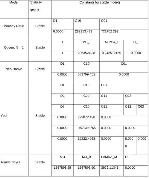
Table 4.1 Material parameters for stable hyperelastic model of NBR at 155% tensile
strain ... 55
Table 4.2 Material parameters for stable hyperelastic model of NBR at 44% compression ... 65
Table 4.3 Experimental test (tensile) vs. Abaqus result ... 67
Table 4.4 Experimental compression (tensile) vs. Abaqus result ... 69
Table 5.1 Result comparisons for various profiles ... 92
Table 5.2 Simulation parameters for thermal analysis ... 100
Table 6.1 Part description of figure 6.2 ... 109
Table 9.1 Input and output variables with associated span values ... 165
Table 9.2 Indicator ... 167
Table 9.3 Rule block A ... 167
Table 9.4 Rule block B ... 168
xviii
Nomenclature
𝐴𝐸: 𝐴𝑐𝑜𝑢𝑠𝑡𝑖𝑐 𝐸𝑚𝑖𝑠𝑠𝑖𝑜𝑛
𝐴𝐼: 𝐴𝑟𝑡𝑖𝑓𝑖𝑐𝑖𝑎𝑙 𝐼𝑛𝑡𝑒𝑙𝑙𝑖𝑔𝑒𝑛𝑐𝑒
𝐴𝑁𝑁: 𝐴𝑟𝑡𝑖𝑓𝑖𝑐𝑖𝑎𝑙 𝑛𝑒𝑢𝑟𝑎𝑙 𝑁𝑒𝑡𝑤𝑜𝑟𝑘
𝐶𝐴𝐷: 𝐶𝑜𝑚𝑝𝑢𝑡𝑒𝑟 𝐴𝑖𝑑𝑒𝑑 𝐷𝑒𝑠𝑖𝑔𝑛
𝐶𝐷𝑀: 𝐶𝑒𝑛𝑡𝑟𝑎𝑙 𝐷𝑖𝑓𝑓𝑒𝑟𝑒𝑛𝑡𝑖𝑎𝑙 𝑀𝑒𝑡ℎ𝑜𝑑
𝐶𝑂𝐹: 𝐶𝑜𝑒𝑓𝑓𝑖𝑐𝑖𝑒𝑛𝑡 𝑜𝑓 𝐹𝑟𝑖𝑐𝑡𝑖𝑜𝑛
𝐶𝑇𝐸: 𝐶𝑜𝑒𝑓𝑓𝑖𝑐𝑖𝑒𝑛𝑡 𝑜𝑓 𝑇ℎ𝑒𝑟𝑚𝑎𝑙 𝐸𝑥𝑝𝑎𝑛𝑠𝑖𝑜𝑛
𝐸𝑆: 𝐸𝑥𝑝𝑒𝑟𝑡 𝑆𝑦𝑠𝑡𝑒𝑚
𝐹𝐸: 𝐹𝑖𝑛𝑖𝑡𝑒 𝐸𝑙𝑒𝑚𝑒𝑛𝑡
𝐹𝐸𝐴: 𝐹𝑖𝑛𝑖𝑡𝑒 𝐸𝑙𝑒𝑚𝑒𝑛𝑡 𝐴𝑛𝑎𝑙𝑦𝑠𝑖𝑠
𝐹𝐸𝑀: 𝐹𝑖𝑛𝑖𝑡𝑒 𝐸𝑙𝑒𝑚𝑒𝑛𝑡 𝑀𝑒𝑡ℎ𝑜𝑑
𝐹𝐸𝑆: 𝐹𝑢𝑧𝑧𝑦 𝐸𝑥𝑝𝑒𝑟𝑡 𝑆𝑦𝑠𝑡𝑒𝑚
𝐹𝐿: 𝐹𝑢𝑧𝑧𝑦 𝐿𝑜𝑔𝑖𝑐
𝐹𝐿𝐶: 𝐹𝑢𝑧𝑧𝑦 𝐿𝑜𝑔𝑖𝑐 𝐶𝑜𝑛𝑡𝑟𝑜𝑙
𝐹𝐿𝑆: 𝐹𝑢𝑧𝑧𝑦 𝐿𝑜𝑔𝑖𝑐 𝑆𝑦𝑠𝑡𝑒𝑚
𝐻𝑁𝐵𝑅: 𝑆𝑎𝑡𝑢𝑟𝑎𝑡𝑒𝑑 𝑁𝑖𝑡𝑟𝑖𝑙𝑒
𝐹𝐾𝑀: 𝐹𝑙𝑢𝑜𝑟𝑜𝑒𝑙𝑎𝑠𝑡𝑜𝑚𝑒𝑟
𝑀𝐹: 𝑀𝑒𝑚𝑏𝑒𝑟𝑠ℎ𝑖𝑝 𝐹𝑢𝑛𝑐𝑡𝑖𝑜𝑛
xix 𝑃𝑎: 𝑃𝑎𝑠𝑐𝑎𝑙
𝑃𝑇𝐹𝐸: 𝑃𝑜𝑙𝑦𝑡𝑒𝑡𝑟𝑎𝑓𝑙𝑢𝑜𝑟𝑜𝑒𝑡ℎ𝑦𝑙𝑒𝑛𝑒
𝑚 = 𝑀𝑎𝑠𝑠 𝑚𝑎𝑡𝑟𝑖𝑥
𝑐 = 𝐷𝑎𝑚𝑝𝑖𝑛𝑔 𝑓𝑎𝑐𝑡𝑜𝑟
𝑘 = 𝑆𝑡𝑖𝑓𝑓𝑛𝑒𝑠𝑠
𝑥 = 𝐷𝑖𝑠𝑝𝑙𝑎𝑐𝑒𝑚𝑒𝑛𝑡
ẋ = 𝑉𝑒𝑙𝑜𝑐𝑖𝑡𝑦
ẍ = 𝐴𝑐𝑐𝑒𝑙𝑒𝑟𝑎𝑡𝑖𝑜𝑛
𝐹 = 𝐹𝑜𝑟𝑐𝑒
𝛺 = 𝑂ℎ𝑚
𝑒 = 𝐸𝑥𝑡𝑒𝑛𝑠𝑖𝑜𝑛
𝜈 = 𝑃𝑜𝑖𝑠𝑠𝑜𝑛′𝑠 𝑟𝑎𝑡𝑖𝑜
𝑊 = 𝑆𝑡𝑟𝑎𝑖𝑛 𝑒𝑛𝑒𝑟𝑔𝑦
𝐼 = 𝑆𝑡𝑟𝑒𝑡𝑐ℎ 𝑖𝑛𝑣𝑎𝑟𝑖𝑎𝑛𝑡
𝜆 = 𝑆𝑡𝑟𝑒𝑡𝑐ℎ 𝑟𝑎𝑡𝑖𝑜
Δ = 𝐼𝑛𝑐𝑟𝑒𝑚𝑒𝑛𝑡
𝜖 = 𝑆𝑡𝑟𝑎𝑖𝑛
𝜎 = 𝑆𝑡𝑟𝑒𝑠𝑠
𝐽 = 𝐸𝑙𝑎𝑠𝑡𝑖𝑐 𝑣𝑜𝑙𝑢𝑚𝑒 𝑟𝑎𝑡𝑖𝑜
xx 𝐷 = 𝐼𝑛𝑐𝑜𝑚𝑝𝑟𝑒𝑠𝑠𝑖𝑏𝑖𝑙𝑖𝑡𝑦 𝑏𝑒ℎ𝑎𝑣𝑖𝑜𝑢𝑟
𝐸 = 𝐸𝑙𝑎𝑠𝑡𝑖𝑐 𝑚𝑜𝑑𝑢𝑙𝑢𝑠
𝐺 = 𝑆ℎ𝑒𝑎𝑟 𝑚𝑜𝑑𝑢𝑙𝑢𝑠
𝐾 = 𝐵𝑢𝑙𝑘 𝑚𝑜𝑑𝑢𝑙𝑢𝑠
𝐾 = 𝐾𝑒𝑙𝑣𝑖𝑛
∞ = 𝐼𝑛𝑓𝑖𝑛𝑖𝑡𝑦
𝛼 = 𝐶𝑜𝑒𝑓𝑓𝑖𝑐𝑖𝑒𝑛𝑡 𝑜𝑓 𝑡ℎ𝑒𝑟𝑚𝑎𝑙 𝑒𝑥𝑝𝑎𝑛𝑠𝑖𝑜𝑛
𝜇 = 𝐶𝑜𝑒𝑓𝑓𝑖𝑐𝑖𝑒𝑛𝑡 𝑜𝑓 𝑓𝑟𝑖𝑐𝑡𝑖𝑜𝑛
𝜏 = 𝑆ℎ𝑒𝑎𝑟 𝑠𝑡𝑟𝑒𝑠𝑠
𝑃 = 𝑃𝑟𝑒𝑠𝑠𝑢𝑟𝑒
𝑄 = 𝑃𝑜𝑤𝑒𝑟 𝑜𝑓 ℎ𝑒𝑎𝑡
𝑉 = 𝑉𝑒𝑙𝑜𝑐𝑖𝑡𝑦
𝜔 = 𝐴𝑛𝑔𝑢𝑙𝑎𝑟 𝑠𝑝𝑒𝑒𝑑
xxi
Published Work
Abubakar, I.J., (2015) Modelling of Rotary Seals and Performance Assessment, James
Walker Seals Symposium and Conference, 16 April 2015, Cumbria, UK.
Abubakar, I.J., Myler, P. and Zhou, E. (2014) Application of Intelligent System in Monitoring
Rotary Lip Seal Damage, 6th International Conference on Engineering Failure and Analysis (ICEFA), 6-9 July 2014, Lisbon, Portugal.
Abubakar, I.J., Myler, P. and Zhou, E. (2014) Optimisation of Elastomeric Lip Seal Design, 3rd International Conference on Mechanical Engineering and Mechatronics (ICMEM), 14-15 August 2014, Prague, Czech Republic.
Abubakar, I.J., Myler, P. and Zhou, E. (2014) Optimisation of Elastomeric Lip Seal Design
Using Finite Element Modelling Approach, a paper submitted to International Journal of Mechanical Engineering and Mechatronics (IJMEM).
Abubakar, I.J., (2013) Lip Seal Design and Failure Analysis, The University of Bolton’s seventh
1
Chapter 1
Introduction
1.1
Background
The increasing speed of mechanical systems, warranted by the desire for increased
productivity, leads to higher operating temperatures that reduce working fluid viscosity. This
factor can cause fluid leakage to prevail. Such leakage in systems carrying highly inflammable
agents cannot be overlooked because of the high possibility of fire hazard. In addition to
wasted resources, unattended leaks can result in downtime, pollute the environment, affect
product quality and cause serious injury, just to mention a few. Of course, it is usually a
common practice to include a safe leakage route in a fluid carrying application, with the aim of
directing all leakage to an escape or collection point, in order to prevent accident. Such
practice is a cumbersome and wasteful solution, both in terms of resources and also the
additional space needed to accommodate the device (Chandrasekaran 2010; Belfort et al.
2011).
2 1.2
Rotary Lip Seal
Rotary lip seals were developed around the 1940s for use in a wide range of equipment and
mechanical applications, such as industrial pumps, compressors, turbines, automobiles and
power plant machines. The primary function of such a seal is to provide an effective means of
sealing a rotating shaft unit, by preventing leakage of lubricant that help inhibit excessive wear
and to avoid penetration of external contaminants into the sealed fluid system (Horve, 1996).
This research is in collaboration with James Walker seals, Cumbria, UK, manufacturer of
rotary lip seals. As such, the work presented in this study focuses on the advanced modelling
of large scale rotary lip seals for the use in wind turbines and stern tube of a marine propulsion.
There exists a variety of methods used to describe the geometries and components of a rotary
lip seal, depending upon the intended application and preference of the seal manufacturer.
Irrespective of the manufacturer’s choice of design, rotary seals fundamentally consist of an
oil resistant sealing element, constructed of an elastomer (NBR, HBNR, FKM) or plastic
(PTFE) which has an elasticity modulus lower than the mating shaft and bonded to a
steel/fibre case. A garter spring is often included in the seal configuration, to augment the
sealing force between the elastomer and shaft, when subjected to heat and chemical attack.
Figure 1.2 depicts a rotary lip seal running on shaft, and Figure 1.3 shows an axisymmetric
3
Figure 1.2 Cut-section of a rotary lip seal running on shaft
(Baart, 2009)
Figure 1.3 Axisymmetric section of a rotary seal running on shaft (Y as the axis of symmetry)
(Shen & Salant, 2007)
The elastomeric element has inner diameter smaller than the shaft external diameter. The
difference between these two diameters is termed “interference”. When the seal is installed, the elastomeric lip is flexed outward, thereby creating a contact force between the elastomer
lip and its mating shaft. Whilst the shaft operates, the elastomer ring will stretch out to follow
a
4
the shaft’s motion, in order to maintain a barrier that prevents leakage. Two different angles
are formed at the point where the seal lip mates with the shaft namely; air side angle (α) and
oil side angle (β). The air side is that portion of the lip surface that faces the air or external part
of the application, while the oil side is the portion of the lip that faces the working fluid. The
angle on the oil side of the seal is steeper than that on the air side with a typical design angle
of 40-45o for β and 25-30o for α when the seal is in a free state. Once installed on the shaft,
these angles change by about 10o. The air side angle is made smaller than that of the oil side,
to ensure that the desired pressure gradient required for pumping action that prevents leakage
is generated (Flitney, 2007).
1.3
Rotary Lip Seal Damage and Seal Failure.
A major setback of radial seals in sealing application is the lack of ability to monitor them
before an impending failure occurs. Therefore, undamaged seals are often replaced during
routine maintenance with the aim of preventing catastrophe. Horve (1996) explained that when
a seal becomes damaged, very often the seal is removed and returned to the manufacturer
with a request that the company explain why the leakage occurred. This is often an impossible
task because the evidence that could define the root cause of failure is not included or is
destroyed when the seal is removed. Chandrasekaran (2010) explained that in a case where
a seal leaks for no apparent reason but shows swelling, blisters or cracks, it could be reacting
with the fluid that it is sealing. This problem of swelling is especially severe if the fluid has a
molecular structure similar to that of the elastomer material. For this reason, seal materials
are normally chosen on the basis of chemical compatibility with the process fluid but, even if
the seal and fluid are chemically compatible, they still can interact physically, thus leading to
leakage. Horve (1996) further highlighted other major causes of seal defects as excessive
wear, high dynamic run out hardened seal lip, broken seal lip, softening of elastomer
component, and coked oil on lip and deep crack. Some of this failure types are presented in
5
1.4
Research Aim
The aim of this research is to develop a framework for the design and development of large
scale seals under a variety of loads and how they can be monitored throughout their service
life.
1.5
Research Objectives
The objective investigates new methods of sealing mechanical systems under thermal and
pressure loads. The work builds upon the initial ideas developed on a special application rotary
lip seal used in wind energy turbines and marine propulsion, in order for alternative system to
be used for new large scale problems, in which the application can be used under increased
pressure. The work is carried out using finite element modelling on nonlinear elastomeric
materials on various profiles, to determine the range of possible geometries for various sized
sealing systems. The new proposed system includes a monitoring system, which can enable
the seal to be monitored throughout its working life and therefore reduce high maintenance
level currently employed.
In achieving these goals, the research:-
Explores rotary lip seals used in mechanical application with the principle of operation.
Provides an overview of the mechanical behaviour of elastomers used in lip seal
design.
Relates the physics of elastomers.
Models the behaviour of elastomers in tension and compression loading conditions
using experiment and finite element modelling.
Validates FE modelling with test data
Replicates a real-life working operation of radial lip seals, using finite element analysis
to satisfy the parameters needed for credible life prediction of seals.
Develops an expert system structure to enable seals and similar engineering assets to
6
1.6
Contributions to Knowledge of the Thesis
In the achievement of the above research objectives, the following contributions are made:
i. An experimental and FE modelling was devised for obtaining elastomer material
properties, that puts into consideration material nonlinearity in lieu of the Hookean
approximate currently used in industries for numerical study of elastomers
ii. A computational modelling technique was devised to investigate different seal profiles
for design optimisation, using FEA to model a seal system instead of the costly trial by
error experimental tests used in industries.
iii. A health diagnostic and life prediction expert system structure was developed, to
enable in-service seals to be monitored and assessed.
1.7
Thesis Structure
The main body of this thesis comprises ten chapters. The outline of the chapters is provided
below:
Chapter 1 : Introduction
Chapter 1 gives an overview of the importance of seals to industrial applications. The
current problems associated with seal failure and the difficultly with seal failure
detection are briefly discussed. It summarises the aim, research objectives,
contributions made and thesis structures.
Chapter 2: Literature Review
This chapter presents the importance of understanding the principle behind lip seal
operation. It gives a review of relevant literatures to understand the working principle
of elastomeric lip seals, via experimental and numerical approaches from existing
work, in order to understand parameters needed for credible seal design and
performance. Finally the chapter summarises problems associated with existing work
7
Chapter 3: Finite Element Modelling
This chapter introduces the finite element methodology, the solution scheme for
nonlinear elastomeric components, and the hyperelastic constitutive models to be
adopted in modelling elastomeric seal in subsequent studies.
Chapter 4: Experimental Analysis and Material Evaluation for Seal Design
In this chapter, mechanical and thermal characterisation of the properties of an
elastomeric seal material are presented and also how these material properties can be
used for lip seal study using FEA. Work in the chapter includes an experimental test
for material data characterisation and also a numerical study of hyperelastic material
parameters that have been obtained.
Chapter 5: Lip Seal Finite Element Modelling and Numerical Study
This chapter presents finite element characterisation of seal design. FEA was carried
out on several seal cross-sections and the results generated were compared against
experimental studies and analytical findings from similar works found in literatures.
Chapter 6: Experiment and Data Correlation Analysis
In this chapter, an experimental test is conducted on lip seal in order to acquire
information concerning seal life, based on a test rig that simulates stern tube for marine
propulsion. In particular, the emphasis of the chapter is to explore the correlation that
exists between measurable variables from the experiment and parameters obtained
from FEA, in order to facilitate the condition monitoring of a seal system.
Chapter 7: Condition Monitoring and Fault Diagnosis for Seal
This chapter presents a literature review to help establish one of the contributions of
this research, which focuses on developing a model that can be used to monitor seals.
The objective of this chapter is to investigate the current techniques and approaches
used in monitoring mechanical face seals and other similar engineering assets, which
8
Chapter 8: Expert System
This chapter looks into how a system can be developed to satisfy seal monitoring using
information which has been obtained in previous chapters from analytical and
experimental studies. Research into expert systems and fuzzy logic is covered, with
the emphasis on their practical application to monitor the seal.
Chapter 9: Development of Expert System for Seal Health Diagnosis and
Life prediction
An ES structure is developed in this chapter based on findings from chapter 8. This
model uses qualitative linguistic rules, obtained from human experiences and the
analytical results from the FEA in chapter 5 and experimental tests of chapter 6, to
adapt the fuzzy logic control rules and adjust the membership functions by training
them with a software algorithm. Also, a computer simulation is carried out to illustrate
the application of the expert system model for seal monitoring.
Chapter 10: Conclusion and Recommendations
This is the final chapter. It summarises the main conclusions from the thesis and makes
9
Chapter 2
Literature Review
This chapter presents a literature study to understand the working principle of elastomeric
lip seals using information found in related existing work. The sections in this chapter explore
the mechanisms required for effective sealing to take place. They also give an insight on how
to achieve a long-lasting performance lip seal. The modelling of lip seals from computational
studies is discussed and the chapter ends by exploring the material behaviour of an
elastomeric lip seal.
2.1
The Working Principle of a Rotary Lip Seal
Elastomeric lip seals appear deceptively simple. A complete and detailed understanding of
the working behaviour, design and modelling has not been attained, the major reasons being
that the physical mechanisms governing the working operation of a radial lip seal is difficult to
observe and develop and also elastomeric materials exhibit a complex and highly nonlinear
material behaviour compared to a Hookean materials, say steel (Horve, 1996).
When a rotary seal is examined closely two important questions usually arise. Firstly whether
there is the presence of a film between the shaft and seal that separate these two regions and
secondly if so, what protects the film from leaking out?
Jagger (1957) showed that a lip seal operating in a steady state condition has a full film
lubrication, which is established at the sealing zone that separates the elastomeric lip from the
shaft. He measured this film thickness and found the thickness to be within the range of 1 −
2𝜇𝑚. He explained that the film plays an important role in reducing wear, thus preventing
mechanical and thermal damage at the seal lip.
Ishiwata & Hirano (1966) estimated pressure distribution between the lip and shaft, and found
10
showed that a film is maintained by the hydrodynamic pressure elevation, generated by
asperities on the lip surface, and explained that best sealing performance is achieved when
the shaft surface is finished to have some roughness. The roughness creates some micro
wear on the sealing tip of the elastomer ring, which are referred to as ‘micro-asperities’ that
help develop lubricating film and minimise further lip wear. Therefore, if the shaft was too
smooth, the seal wear band will not develop. On the other hand, if the shaft was too rough,
the seal would be severely damaged before the protecting lubricating film is formed. His work
concluded that micro-asperities on the seal lip support the film, by acting as micro bearing.
Figure 2.1 Micro-asperities on elastomeric lip seal
(Flitney, 2010)
As for the film not leaking out, it was widely accepted that surface tension was responsible for
this factor, until (Kawahara & Hirabayashi, 1978) reported that a proper functioning seal would
leak freely if installed reversely (i.e. the oil side facing the atmosphere and vice versa). Their
work showed that leakage depends on shaft speed, viscosity, surface condition and running
time.
Studies found in (Ott, 1983) and (Muller & Ott, 1984) explained another dynamic sealing effect
11
creates an inward pumping action that prevents fluid leakage, whilst expelling contaminants.
A phenomenon which is referred to as ‘reverse pumping action’ depicted in Figure 2.2. This
lead to a conclusion by many researchers, that the hydrodynamic effect of the lubricating fluid
rather than the surface tension was responsible for a leak free fluid film.
Figure 2.2 Hydrodynamic pumping action of a rotary seal
(Parker, 2006)
Kammüller (1986), Muller (1987) found that as the shaft rotates, the micro-asperities are
sheared in the tangential direction. These sheared micro-asperities are irregular due to uneven
pressure distribution across the sealing zone, with region around the oil side possessing
maximum sealing pressure. This factor causes maximum shear deformation to occur around
12
Figure 2.3 Orientation of asperities during shaft rotation
(Flitney, 2010)
2.2 Rotary Seal Profile Description.
The development of a specific shaft lip seal for general purpose application is practically
impossible. The main reason for this is that different applications operate at dissimilar
conditions such as, different temperatures, pressures, process fluids and even operating
environments. For example, an application involving high circumferential speeds and high
dynamic eccentricity and/or considerable offset between the shaft and the housing, requires
a long and flexible sealing lip as opposed to an application involving pressure resistance which
would require the shortest possible sealing lip (Tietze 1998; Freudenberg 2002).
The above concept was illustrated by Dichtungs (2003), by using two radial seals of different
13
Figure 2.4 Dependence of seal lip contact force on its length.
(Dichtungs, 2003)
Dichtungs (2003) explained that the longer the sealing lip (dimension b), the larger the
effective pressure area (A), therefore the greater the sensitivity to operating pressure. The
graph in Figure 2.4 demonstrates this point by showing how the contact force at the seal lip
would be affected by the sealed fluid pressure.
Seal design looks deceptively simple, but the development of radial shaft seal for relatively
zero leakage is usually focused on achieving leak free operation and long service life. Some
companies achieve this aim by developing several customised radial shaft seals (Parker,
2006), each of which is suitable for use in a specific application.
14
Figure 2.5 Rotary seal geometry
1. Lip length
2. Flex thickness
3. R Value
4. Oil Side Angle
5. Air Side Angle
6. Garter Spring
7. Frame
8. Seal Outer Diameter
9. Seal Inner Diameter
The overall geometry of the seal will increase in size as the shaft size increases. The lip length
is the axial distance from the spring centre point to the flex point. Increasing the lip length will 1
2
3
4 5
6
7 8
9 Air side
15
increase flexibility, reduce beam forces and improve seal’s ability to follow shaft vibrations and
dynamic run out. Decreasing the beam length will increase radial load and increase seal and
shaft wear. Short, thick lips are suitable for higher pressure applications (Horve, 1996),
(Flitney, 2007).
Thick flex sections will increase the seal load on the shaft and reduce followability, often used
in pressure and reciprocating applications. Thin flex sections reduce the seal load on the shaft
and increase followability but, if too thin, can wrap around a rotating shaft (Horve, 1996),
(Flitney, 2007).
The R value is the axial distance between the spring centreline and the lip contact point. The
spring centreline must be positioned towards the air side of the seal contact point. This
condition is known as a positive R value. If the R value is negative, the spring centreline is
positioned toward the oil side of the seal contact point. The pressure distribution between the
lip contact region and the shaft is reversed if the R value is negative, and instant leakage will
occur (Horve 1996; Flitney 2007).
The oil side angle is the angle between the oil side surface and the shaft surface, whereas the
air side angle is the angle between the air side surface and the shaft. Kammüller (1986)
suggests that the air side angle should be smaller, compared to the oil side angle, in order to
ensure that the desired pressure gradient is generated between the seal lip and shaft.
The garter spring serves to minimise load and interference loss, which occur when the
elastomer lip absorbs oil at exposure to higher temperatures, thereby reducing the elastomer’s
tendency to soften and expand (Horve 1996; Flitney 2007).
2.3
Numerical Modelling in Lip Seal Design Study
Lubricating film plays an important role in reducing wear, as it prevents mechanical and
thermal damage on the elastomer lip. Numerous research work have been conducted to
16
investigated seal surface treatments, such as coating (Pei, et al., 2008), texturing (Ayala et al.
1998; Etison 2004). Some addressed the effects of shaft surface finish on sealing performance
(Kunstfeld & Haas 2005; Kanakasabai 2009; Jia et al. 2011). Several authors studied seal
material compound modification (Haworth 2007; Felhos and Kocsis 2008; Karger-Kocis et al.
2008).
The relative motion between two mechanical components always generates frictional heat
between the surfaces. Also, shear forces may be created that resist the tangential motion of
the bodies at their point of contact (Abaqus, 2012). Numerical modelling is one of the most
viable methods employed by many researchers to study lip seal contact problems by modelling
areas on the surfaces that are in contact and to calculate the contact pressure generated
(Bignardi et al. 1999; Belforte et al. 2009).
Kim & Shim (1997) carried out a coupled thermal-mechanical analysis of lip seal, using
nonlinear finite element analysis software, to analyse contact force and thermal behaviour of
a lip seal, both with and without the effect of a garter spring, as a function of shaft interference
by increasing shaft diameter. Their FEA results were compared with experimental values
measured using a contact force measuring device. Contact force was found to increase
linearly, with increasing interference between seal and shaft. The contact force with the garter
17
Figure 2.6 Experiment vs. FEA result on the effect of contact force
(Kim & Shim, 1997)
Results from their work also showed that thermal stresses have a very small influence on the
deformed shape of the lip seal, as the shaft interference increases. This is presented in Figure
2.7 and 2.8
Figure 2.7 Mechanical vs. thermal-mechanical analysis on the contact force
18
Figure 2.8 FEA showing high stress around the contact region
(Lee, et al., 2006)
Lee, et al. (2006) expanded Kim & Shim’s study, in order to investigate the contact pressure
on the air side and oil side, also using different interference values. Their simulation result
showed that pressure at the lubricant side (oil side) had a greater slope increment than the air
side of seal lip. This was believed to occur due to the steeper angle of the lip in the oil side
than the air side. The work also shows that as the shaft interference increases the contact
width becomes bigger, although the change in air side was more significant as shown in Figure
19
Figure 2.9 Air side contact pressure for different shaft sizes
Lee, et al. (2006)
2.4
Effect of Shaft Surface on Lip Seal
It has been shown in section 2.1 that in a lip seal under a steady operating condition, a micron
scale lubricating film (mostly trapped within the shaft surface) separates the lip from the shaft.
This film prevents damage to the lip from the excessive heat generated and also the
mechanical stresses at the lip–shaft interface. As shown in Figure 2.10
Figure 2.10 Schematic of Sealing Zone
(Salant & Shen, 2003)
These asperities are also responsible for the sealing mechanism. Typically the Ra of the shaft
surface is one-tenth of that of the lip surface. Qu (1995, 1996) explained that the shaft surface
20
roughness would cause the seal to wear out quickly, if too smooth, the seal would be unable
to retain the lubricant. This concept is reflected in the Rubber Manufacturers Association of
the USA (RMA) standard on upper and lower limits on shaft surface Ra, and in DIN 3760/3761
in Germany, and in ISO 6194/1. More recently, a number of studies have revealed that, not
only is the amplitude of the shaft surface fluctuations (as measured by Ra) important, but that
the shaft surface profile is also important (Salant & Shen, 2003).
However, unlike the state of knowledge regarding lip surface roughness, no theoretical basis
for understanding the influence of shaft surface roughness has been developed to date.
Nonetheless, Salant (2003) reported that the shaft surface roughness could affect lip seal
behaviour through a number of possible mechanisms:
• Irregularities on the shaft surface provide reservoirs to store liquid under static conditions,
and supply liquid to form the lubricating film at start-up;
• The shaft surface conditions the lip during the break-in period, generating asperities on the
lip surface by preferential wear;
• Asperities on the shaft may affect static adhesive forces on the lip;
• Shaft surface fluctuations affect the load support and sealing mechanisms through the
hydrodynamics of the lubricating film.
Jia, et al. (2011, 2012) quantified the effect of the shaft surface finish on seal performance
based on their work that had previously shown that the shaft itself can induce a pumping
action. Their study used a laser structured shaft to validate pumping action of seals along with
a polished shaft without any structure (non-pumping). Figure 2.11 schematically depicts
21
Figure 2.11 Schematic of structured shafts
(Jia, et al., 2011)
In their work, a variety of groove patterns were applied to the shafts, with a variation in depth,
groove density (number of grooves around circumference) and groove angle (with respect to
the shaft circumference) in order to get different pumping rates. The procedure they used to
determine the pumping rate of the shaft surface is shown in Figure 2.12. They obtained the
pumping rate of the shaft surface by subtracting the pumping rate of the smooth, polished
shaft from the pumping rate of the test shaft (with structures) Figure 2.13. Their result showed
that shaft roughness plays an important role in retaining process fluid since the laser structured
surfaces were able to pump more fluid as compared to the smooth shaft surface. As such,
when the textured surface wears out, leakage will begin to occur in a seal because it has lost
22
Figure 2.12 Measurement of pumping rate
23
Figure 2.13 Pumping rate vs. shaft parameters; (A) Pumping rate vs. groove angle; (B)
Pumping rate vs. groove density (number of grooves around circumference); (C) Pumping
rate vs. shaft-speed; (D) Pumping rate vs. groove depth.
(Jia, et al., 2011)
Another study by Kunstfeld & Haas (2005) estimated the suitability of shaft surfaces
manufactured by different processes, to assess their pumping characteristics and test them to
evaluate their sealing and pumping behaviour. The emphasis of their investigation was based
on hard turning process. Plunge turning, tangential turning, non-hardened shaft surfaces,
plunge ground shaft surfaces were all investigated. Figure 2.14 shows the surface
topographies of the different manufactured shaft surfaces used in their study
A B
24
Figure 2.14 Shaft surface topography
(Kunstfeld & Haas, 2005)
Their test was run for 1000 hours for the shaft models which were made to rotate in the
clockwise and anticlockwise direction, with air sided flooded to with oil in order to inwardly
pump fluid using the same approach found in (Kawahara & Hirabayashi, 1978). The pumping
mechanism of the seal continuously pumps oil outwards, which is measurable as leakage
presented in Figure 2.15. Their work provided possibilities for the evaluation of shaft surface
25
Figure 2.15 Pumping rate of shaft for different manufacturing methods
(Kunstfeld & Haas, 2005)
2.5
Lip Seal Material
Lip seal elements are made from elastomers because they possess a unique property that set
them apart from other machine element materials, such as steel. Elastomers consist of long
flexible molecules that are in continuous Brownian motion at normal temperature, due to
agitation. When the molecules are stretched out from applied force and released, they spring
back to random shapes as fast as their thermal motion allows. This is the origin of the unique
ability of rubber to undergo large elastic deformations and recover completely. This
phenomenon of the recoverability characteristic of an elastomer is a factor that makes them
ideal for use in sealing applications (Flitney 2010; Gent 2012).
Elastomers exhibit hyperelasticity, complicated nonlinear behaviour, such as hysteresis and
viscoelasticity. Therefore the conventional elastic-plastic material models cannot accurately
predict their behaviour in application, where they are subjected to high strain and since
Poisson’s ratio for elastomers is between 0.499 and 0.5 corresponding to an incompressible
26
Figure 2.16 depicts a comparison between an elastomer and a traditional linear elastic
component in terms of material behaviour
Figure 2.16 Nonlinear elastic behaviour vs. linear elastic behaviour
(Jaker, 2010)
According to Gent (2012) the stress-strain behaviour of elastomers remains elastic up to large
strain values (often well over 100%) hence it is classed as a “hyperelastic material”. They do
however exhibit a Cauchy-elastic material behaviour like other simple elastic material. That is,
the stress at each point is determined only by the current state of deformation with respect to
an arbitrary reference configuration and not the path or history of deformation. Also for
hyperelastic materials, the stress-strain relationship is derived from a strain energy density
function and not a constant factor. It is worth noting from Figure 2.16 that hyperelastic
materials exhibit a nonlinear stress-strain behaviour, in other words, the deformation is not
directly proportional to the applied load, and still maintains its elastic properties at large strains.
For such material, the Poisson’s ratio 𝜈 of lateral to longitudinal strains is only constant at small
strains. It becomes a function of the strains themselves when they are no longer small
therefore at large strains the concept of a single value for the strain ratio is invalid and
27
Several works have devised a couple of hyperelastic models to represent an elastomer
deformation behaviour under load and this will be later explored in chapter 3 and 4. Some of
the recent works on characterisation of elastomers, using hyperelastic constitutive models,
are seen in (Sasso et al. 2008; Khajehsaeid et al. 2013; Beda 2014). The development of
hyperelastic material coefficients from test data, using finite element programs, can be seen
in the methodology adopted in (Singh 2009; Ghoreishy 2012; Abaqus 2012).
2.6
Conclusion
The principles of lip seal operation have been explored in this chapter. Reviews from past
studies cover both experimental and theoretical work on rotary seals. The literatures
demonstrated that a mixed elastohydrodynamic lubrication model of a rotary lip seal, with
micro-asperities on the shaft surface, can generate the important characteristic parameters,
such as load support, contact load ratio, the reverse pumping rate and the average film
thickness for lip seal operation. It has also shown that the micro-asperities on the shaft surface
are beneficial, in so much that they actually help to improve the sealing capability whilst
reducing the lift-off speed.
Shaft-Seal contact studies have been explored. Finite-element analysis was employed in
literatures to investigate the contact characteristics of the lip seal with the shaft at different
interference fits. However, literature is poor regarding the investigation of the characterisation
and optimisation of lip seal design using finite element computational modelling, and also in
the study of coupled thermal mechanical analysis on contact problem, which can help to
establish the parameters needed for credible life prediction of seals, since sealing of fluid
actually occurs at the shaft-seal interface. As such, the main difficulty is a lack of an accurate
analytical model to describe a lip seal model subjected to real life working condition, and it is
intended to be addressed in this research work.
Furthermore, an assumption adopted so far by industries in modelling lip seal is through using
linear elastic modulus, while setting Poisson’s ratio 𝜈 to a value very close to 0.5, to
28
fact that elastomeric materials even though elastic, are highly nonlinear. For this reason, a
material parameter has to be developed to minimise errors that could arise from such an
assumption in computational finite element modelling, and this will be explored in detail, later
29
Chapter 3
Finite Element Modelling
This chapter describes background theory behind finite element analysis and modelling for
later use to carry out lip seal design study. The FE Analysis and Modelling are approach to
design seal in this work. Large strain hyperelasticity theory that accurately model
elastomeric material is also presented in this chapter.
3.1
Introduction
Finite Element Analysis (FEA) is a numerical method which furnishes solutions to relatively
simple or complex problems. It consists of a model structure with specific material properties
and geometry with certain boundary constraints, which is subjected to a predefined load type.
The model is then analysed for particular problems in order to obtain specific results. FEA is
generally used for design and conception of non-existent structure and for the existent product
modification and improvement. A numerical simulation of a given structure provides the
designer with valuable information which ensures that the adopted structural design is suitable
for the purpose that is intended to serve (Pascali & Cherif, 2012)
Finite element Analysis provides the capabilities of modelling complex engineering problems
more than just within the structural (stress/displacement) domain. It can handle problems in
diverse areas including heat transfer, electromagnetics, and mass diffusion etc.
In finite element modelling, the physical body to be modelled is first divided into a whole set of
finite elements. These elements are connected together at nodes, all put together into a finite element mesh, (Figure 3.1) and the process of dividing the whole body into small elements is called discretisation. A stiffness matrix is generated for each element, in which the combination of all the individual stiffness matrices is referred to as a global stiffness matrix for an accurate
30
Figure 3.1 Physical model (A) and finite element mesh (B) of a tube
3.2
ABAQUS
®There are some commercial FEA programs readily available to simulate for a variety of real
world problems such as Abaqus®, ANSYS®, COMSOL Multiphysics®, LS-DYNA®, and
MATLAB®. However, the ABAQUS® analysis software is used in this research work because
of its capability to solve highly non-linear engineering problems. The software is widely used
in academic and research institutions, due to the broad material modelling capability, and the
program’s ability to be customised. It can effectively model rubbers because of its rich material
library and also efficiently evaluate parameters for hyperelastic materials.
3.3
FEA Solution Process
The FEA solution process is a three stage progression comprising of: - pre-processing, solving
and post-processing. The general procedure for running a simulation, irrespective of the
software package, is very similar and the overlap in their capabilities is usually high. The chart
in Figure 3.2 depicts a finite element analysis solution process.
31
Figure 3.2 FEA simulation process
(Bathe, 1982)
3.3.1 Pre-Processing
Pre-processing involves the development of a computer generated model for analysis,
producing a finite element mesh of the model, assigning material properties and defining
boundary and load conditions to the model.
The material properties required depend on the type of analysis result needed. For example
a structural analysis will require an elastic modulus 𝐸, Poisson’s ratio 𝜈 and some cases the
material’s density 𝜌. For a thermal analysis, the thermal properties of the material would be
needed. Examples of boundary conditions are defining a nodal translation or temperature, and
assigning contact conditions. Loads include forces, pressures and heat flux.
3.3.2 Solving
In the solving phase of FEA, the computer takes over and solves the set of equations that the
finite element method generates and also conducts numerical analysis by solving the
boundary value problem. Once the solver is completed, all the unknown initial variables such
32
3.3.3 Post-Processing
This is the last step in the FEA. According to Nammi (2011) during this phase the outputs
generated at the nodes are exploited using interpolation functions. The additional quantities
such as stress, strain, temperature etc. in each element are computed. The routines resident
in the finite element software allow sorting, plotting and data analysis of results. Depending
on the software capabilities, the solution data can be manipulated in many ways. Many
commercial FE codes allow operations such as sort element strains in the order of magnitude,
plotting the shape of a deformed solid, animate the dynamic behaviour of a solid under load
and plotting stresses in relation to factor of safety etc.
3.4
FEA Solution Integration Scheme
The finite element method can be solved using two different procedures termed “implicit and
explicit” methods. In the implicit method a solution to the set of finite element equations
involves iteration until a convergence criterion is satisfied for each increment. The finite
element equations in the explicit method are reformulated as being dynamic and in this form
they can be solved directly to determine the solution at the end of the increment without
iteration (Harewood & McHugh, 2006).
According to Michael, et al., (1977) the fundamental difference between an implicit and explicit
integration scheme is that, in the explicit case, the displacement vector for the current time
step in the analysis can be predicted directly from the known displacements, velocities and
accelerations of the previous time steps, whereas, for implicit the current displacements are
related to current accelerations (and possibly current velocities), as well as response from
previous time steps. As a result, the solution algorithm for the implicit scheme requires
assembling a global stiffness matrix into a set of coupled algebraic equations and solving the
system by some techniques, such as Gaussian elimination. The explicit algorithm, on the other
33
the need to assemble the global stiffness matrix. If a lumped mass procedure is used (as is
generally done), the accelerations are uncoupled and can be computed rapidly.
The implicit approach is useful in problems in which time dependency of the solution is not an
important factor e.g. static structural and modal analysis, whereas explicit approach is helpful
in solving high deformation time dependent problems such as impact, crash, blast etc.
Considering the equation that relates mass, damping, stiffness and force as shown below
𝐹 = 𝑚ẍ + 𝑐ẋ + 𝑘𝑥 3.1
Where
𝑚 = Mass matrix
𝑐 = Damping matrix
𝑘 = Stiffness matrix
𝑥 = Displacement vector
ẋ= Velocity
ẍ = Acceleration
𝐹 = Load vector time
3.4.1 Implicit Scheme
In this scheme, the displacement is not a function of time. Therefore, the velocities and
accelerations which are time derivatives of displacement turn out to be zero and the mass and
damping factors can be neglected. In order to solve an FEM problem using implicit method,
an inversion of stiffness matrix (𝑘) is required. For a very large deformation, problems such as
crash analysis, can result in millions of degrees of freedom, effectively increasing the size of