A NUMERICAL METHOD FOR THE DETERMINATION OF
AN EFFECTIVE MODULUS FOR COATED GLASS FIBERS
USED IN PHENOLIC COMPOSITES
V. Nassehi
Chemical Engineering Department, Loughborough University Loughborough, Leicestershire, LE11 3TU, UK
S. A. Hashemi and M. H. Beheshty
Iran Polymer Institute P.O. Box 14185/458, Tehran, Iran
(Recived: April 21, 1998 - Accepted in Final Form: May 1, 2000)
It is well known that the mechanical properties of fiberglass reinforced "phenolic Abstract
mou lding compounds" are significantly enhanced if the glass particles are coated with silane coupling agents before compounding. It has been shown that improvements obtained by using scanning electron microscopy techniqu es are du e to better bonding of phenolic resin to the su rface of treated glass fibers. These observations prove that coated glass fibers effectively exhibit properties which are different from those of the glass itself. Thus from a modelling point of view, they can be regarded as materials having moduli different from the modulus of glass. However, considering the very small width of the coating layers used, it cannot be expected that by u sing direct experimental measurements of relatively large specimens, significantly different modu li fo r u ncoated and coated glass fib ers will be fo u nd. In this paper, the notion of an effective moduli for coated fibers is introduced. It is shown that such values can be numerically determined using experimentally measured bu lk mechanical properties of coated glass filled composites. A trial and error procedure is developed for obtaining optimu m modu li for the reinforcing phase. This scheme is based on the comparison of simulation results obtained by a previously validated finite element technique and data collected from flexural tests and fracture surface observations for different types of glass reinforced phenolic composites.
Glass Reinforced Composites, Silane Coupling Agents, Flexural Strength, Finite Key Words
Element Modelling, Effective Moduli
LK Ð[6 "R>" ]"J . 5W. #$5W5X" ,Pc -{ Q" 5Q1# K" ÐRw ,"Pc
¨¨LL««uuB
B
Q" KO"K LK#_§6" §"§Í #§ L4z§6 Df§X L#\2 K# L 4z6 K# Å" P2 Ì #$ ÐR§w ,"Pc z5W P!Q"L" 4X" O#W. Ì L4z6 DfX L#\2 4#Ic Ð#=$ K"§ "P§. ,"P§c §" P§!Q"L§" "P§. z5W Ps YO Ï #z " OK 4W Ð " ]"J 4X" L\ "O" w QO VP6# OK LK#_6" "Í #. L\ K"KZ\2 [\ t#" Q" Ð[5 5Q1#! .#z OK K" " Ì"VÐÍ "P. L$4XL. <#5 W#z KLE "R>" YO Q" K#v5X" #- P. YO " L\#. Z#Q$ <#5 #. [[ #P1. INTRODUCTION
In order to improve the energy absorption properties of polymeric composites under impact loads and enhance their flexural and yield strength it is necessary to prevent the build up of harmful peak stresses at the fiber/matrix
bonding [1,2,3]. Amongst the most important materials which are used to coat fiberglass reinforcing phases are the silane coupling agents [4-7]. The silane coupling agents significantly improve the bonding between the fillers and polymer matrix. Extensive studies of their properties can be found in the literature [8-12]. The way these coupling agents affect the microscopic behaviour of fiberglass reinforced polymeric composites depends on factors such as the type of the polymer and the shape and size of the reinforcing phase. Due to the excellent mechanical properties and their high electrical and thermal resistivities, phenolic moulding compounds are widely used in various industrially important composites [13].
Detailed experimental work has been carried out to gain insights about the behaviour of phenolic composites. For example the cure reaction of these materials have been determined experimentally to be related to the degree of coupling between the fiberglass and polymer matrix [14]. It is however, very difficult to obtain quantitative data about stress distribution patterns at the fiber/matrix interface for composites under various types of loading by experimental techniques. Such data can be usually found by finite element modelling.
In the present work, bulk flexural modulus of glass reinforced phenolic composites are first determined by experiment. Next, an in-house developed finite element model was used to compute the flexural modulus of the composite under study via simulated stress/strain data [15,16] and to compare the calculated modulus with the experimental results. In the finite element simulations, individual modulus of matrix and reinforcing fibers should be used as input. However, in the case of coated glass fibers ideally one needs to use separately
measured modulus of the glass itself and the layer which coats the glass. The exact experimental measurement of the modulus of the thin coating layer is not possible and the flexural tests of "macroscopic" scale specimens of coated or uncoated glass cannot be expected to yield significantly different results. Therefore, for the coated glass, the calculations start by inserting the measured modulus uncoated glass. Then using the comparison of the computed results for the composite specimens with the bulk experiments as a guide, the modulus of the coated glass is adjusted. This procedure is repeated until an acceptable comparison between experimental and computed results is achieved. It should be noted that due to the small difference between the modulus of coated and uncoated glasses found by macro-scale flexural tests the described procedure can also be carried out by the introduction of the modulus of the coated glass as the initial value in the iterations. Thus we define an effective flexural modulus for coated glass fibers which gives a simulation close to the actual experimental behaviour of the composites. Using the determined effective moduli of coated glass fibers other useful information such as normal stress and strain and Von Mises stress at the fiberglass/polymer matrix interface are found.
2. EXPERIMENTS
TABLE 1. Experimental Flexural Strength, Modulus and Strains. Flexural Stains Flexural Flexural Test TYpe of (%) Modulus (GPa) Strength (MPa) Condition fiberglassused 0.84 8.5 74.0 Normal As Received 0.89 8.2 70.4 Wet (Commercial) 0.81 8.5 67.9 Dry 0.80 8.8 76.1 Normal Coated with 0.84 8.6 74.2 Wet AMEO 0.81 8.7 75.1 Dry 0.74 9.8 84.5 Normal Coated with 0.78 9.6 82.0 Wet AMEO-T 0.77 9.7 82.5 Dry 0.62 7.7 39.4 Normal Thermally 0.76 4.7 30.4 Wet Treated 0.62 4.8 26.1 Dry
of fiberglass reinforced polyesters. We used Dynasylan AMEO and Dynasylan AMEO-T produced by Dynamite Noble Co. of Germany as the coupling agents. The manufacturer has specified the chemical formula for Dynasylan AMEO as H2N(CH2)3Si(OC2H2)5 which is designated as a J-amino- propyltriethoxysilane. AMEO-T is a technical grade of the commercial AMEO coupling agent.
Industrially important phenolic composites contain high volume fractions of reinforcing phase Therefore composites which contain as much as 50% by weight fiberglass were considered here. Four different kinds of fiberglass were used. These were "as received" chopped glass fibers (containing small amount of an unspecified silane coupling agent), thermally treated glass fibers, thermally treated fibers coated with AMEO silane agent and thermally treated glass fibers coated with AMEO-T silane agent. Compounding the premixed materials was carried out in a two roll mill with a friction ratio of 1.4 at 12 rpm for five minutes at 120 C. The sheet of compound was
conditions. Wet specimens were prepared by soaking the samples in boiled distilled water for 4 hours. In order to prepare a dry specimen, first a wet sample was made and then it was thoroughly dried in a vacuum oven. As it is described in the next section the experimentally obtained results for different specimens were treated as the benchmark guide in the developed finite element algorithm.
Scanning electron microscopy using Cambridge S360 microscope was performed to monitor the uniformity and effectiveness of fiber coating and polymer/fiber bounding. Scanning electron micrographs of each specimen after being subjected to a flexural test were also prepared and examined to determine the occurrence and nature of fracture surfaces in the composite.
3. FINITE ELEMENT MODEL
Details of our finite element model have been published elsewhere [15,16] and only a brief account of it will be given in this paper. Our model is based on the finite element solution of the following governing equations:
(1) Vij/xj+ fi= 0
(2) uj/xj= 0
where Vij, fi and ui represent components of
total stress, body force (load) and displacement, respectively, in the Cartesian co-ordinate system (xj, j = 1,2). In this model the total stress components are defined as:
(3) Vij= -PGij+ Wij
where p is the hydrostatic pressure, Gij stands for the components of the unit second order tensor (Kroneker delta) and Wij denotes
deviatoric stress components.
Equation 1 represents the equilibrium of internal and body forces acting on composite specimen under a given load and Equation 2 is
the expression of material incompressibility. Equations 1 and 2 can be used to describe the deformation of an elastic solid in penalty finite element schemes [17]. Their solution requires applied loads and/or displacements and the locations of fixed points (i.e. points where displacement is zero) along the geometrical boundaries of the domain of study. In the finite element model used in this work the composite domain of known dimensions is first discretised into a number of nine noded Lagrangian elements. Then a weak variational statement based on the governing equations is derived using continuous penalty Galerkin weighted residuals method. The derived statement is valid for every element. Thus the repeated application of the procedure for all of the elements in the solution domain and subsequent assembly of the elemental equations gives a set of algebraic global finite element equations which describe the deformation of the composite. After the prescription of the boundary conditions the global set of equations becomes determinate and its solution yields the displacement values at all node. The computed displacement field is then used to calculate nodal stresses via a variational recovery method [18].
composite specimen and use this data in a trial and error cycle to find optimum effective moduli for coated fibers. In our procedure initially all of the simulations start using typical values of flexural modulus for phenolic resins and uncoated glass fibers. After obtaining the first set of results average stresses along different directions in the solution domain are found and used to calculate the modulus of the composite. Then for each case the calculated value of the modulus is compared with the experimental results. The first guess modulus for the reinforcing phase is then adjusted and a new solution is obtained. This process is repeated until a final value for the modulus of coated fiberglass is found which gives a composite modulus close to the experimentally determined value. The choice of the nodal positions at which average stresses should be used to calculate a composite modulus comparable with the experimental conditions depends on the nature of imposed boundary conditions [15]. The determination of optimum flexural modulus for various types of coated fiberglass enables us to find stress distributions on the fiber/matrix interface and form a judgement about the overall behaviour or particular composites.
Von Mises stresses along the nodes corresponding to fiber/matrix interface are also found using the following equation
2
2 (4)
Vv=
(
V1+V2-V1V2+3W12)
1/2where indices 1 and 2 represent respective Cartesian components of the total and deviatoric stress. In the present work we do not take into account plastic deformations of composites and thus a criteria for their failure by yielding based on a critical value of Von Mises stress at the fiber/matrix interface is considered. This criteria however, may not be
appropriate if in practice these composites are found to be very brittle [19]. In this case the predicted normal stress or normal strains at the fiber/matrix interface should be used to analyze their behaviour at the point of failure.
4. RESULTS AND DISCUSSION
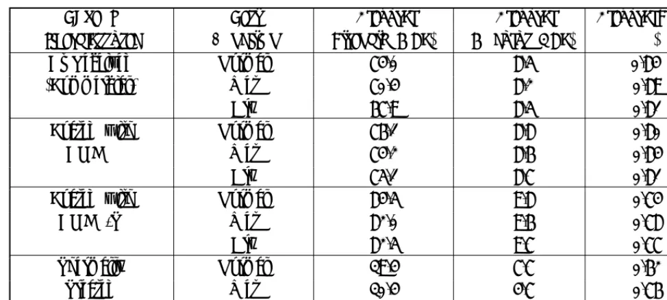
TABLE 2. Computed Normal Stresses At Sample Interfacial Nodes A, B and C (Figure 1) And Maximum Von Mises Stress.
Maximum Von Normal Stress in
Normal Stress in Test
Type of
Mises Stresses X2Direction
X1Direction Condition fiberglassused (MPa) (MPa) (MPa) Computed C B A C B A 67.7 43 40 54 39 42 48 Normal As Received 55.8 35 40 46 32 38 44 Wet (Commercial) 64.9 43 39 52 39 42 46 Dry 70.7 45 43 59 41 44 49 Normal Coated with 50.0 43 41 54 40 41 48 Wet AMEO 59.6 44 42 52 40 43 48 Dry 67.5 47 49 62 43 45 51 Normal Coated with 49.4 45 42 56 41 42 49 Wet AMEO-T 51.6 43 44 61 42 44 50 Dry 65.1 38 36 47 32 35 37 Normal Thermally 57.4 33 32 27 30 31 29 Wet Treated 60.2 24 27 28 24 21 20 Dry
Figure 1. Finite element mesh; A, B and C stress sampling nodes; V1 Position of predicted maximum Von Mises stress using cleaned fibers. V2 Position of predicted maximum Von Mises stress using coated fibers.
of the uncoated glass fillers. Experimentally obtained flexural strain values for all of the cases are also given in Table 1. Maximum strains were found to occur under wet conditions for all types of composites used in this study. This may be due to the plasticising effects of water.
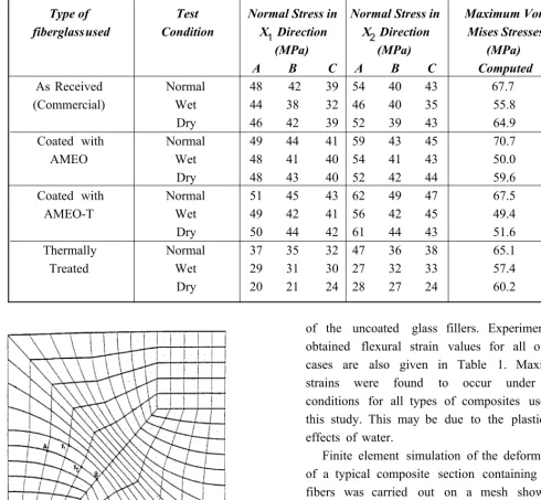
(a)
(b)
Figure 2. Scanning electron micrograph of fracture surface of composite containing commercial fiberglass: (a) magnification 850 and (b) magnification 1800.
calculated at three sample nodes (A, B, C, Figure 1) located at the fiber/matrix interface are given in Table 2. These values are based on the use of fiberglass flexural moduli adjusted using the previously described trial and error procedure.
(a)
(b)
Figure 3. Scanning electron micrograph of fracture surface of composite containing fiberglass coated with AMEO: (a) magnification 600 and (b) magnification 1950.
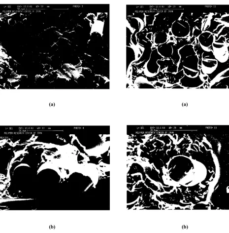
(a)
(b)
Figure 4. Scanning electron micrograph of fracture surface of composite containing fiberglass coated with AMEO-T: (a) magnification 860 and (b) magnification 1700.
maximum Von Mises and normal stresses for different composites are also given in Table 2. The presented finite element results show a large difference between the deformation behaviour of composites containing coated or uncoated fiberglass and by comparison the
(a)
(b)
Figure 5. Scanning electron micrograph of fracture surface of composite containing thermally cleaned fiberglass. (a) magnification 800 and (b) magnification 1800.
difference between the behaviour of composites containing glass fibers coated with different silane coupling agents is not very significant.
the micrographs of composites containing different types of coated fiberglass obtained using specimens subjected to flexural tests. In some cases, as it is shown in Figures 2-4, the bonding between coated fiberglass and polymer matrix is strong enough to remain relatively intact after the application of 10 kN load in the flexural tests.
In contrast, the Figure 5 shows the appearance of fracture surfaces between the cleaned glass fibers and the polymer matrix. This corresponds to the stress distribution patterns predicted by the finite element model.
5. CONCLUSIONS
Our results show that the mechanical behaviour of fiberglass reinforced phenolic composites are clearly affected by the coating of the glass fibers with silane coupling agents prior to compounding. The most significant improvement of these properties is however, achieved after using coated fiberglass instead of uncoated material and in comparison the use of different silanes have a limited effect in this respect.
Results obtained by our finite element analysis of composites containing coated and uncoated fiberglass used in this study also confirm this point. It is shown that a trial and error procedure can be successfully used to determine an effective (optimum) modulus for coated glass fibers which takes into account greater compatibility of the fiber/matrix interface achieved after coating glass particles with silane coupling agents.
6. REFERENCES
1. Lubin, G., "Handbook of Composites", Van Nostrand, New York, pp. 149-155, (1982).
Press, New York, pp. 70-98, (1987).
3. Kn o p , A., a n d P ila t o L . A., "P h e n o lic R e sin s, Chemistry, Applications and Performance", Springer Verlag, Berlin, pp. 196-212, (1985).
4. Plueddemann, E. P., "Silane Coupling Agents", Plenum Press, New York, pp. 1-27, and pp. 111-140, (1982). 5. Mani, P., Gupta A. K. and Krishnamoorthy S., "Effect
of Silane Coupling Agents on Mechanical and Thermal Pro pert ies of P olye ster R esin Co ncre te", Journalof Materials Science, Vol. 18, (1983), 1506-1514.
6. Culler, S. R., Gillette P. C., Ishida H. and Koenig J. L., "Factor-analysis Applied to a Silane Coupling Agent on E -glass Fib er Syste m",Applied Spectroscopy, V ol. 38, (1984), 495-500.
7. Wu, H. F., Dwight D. W. and Huff N. T., "Effects of Sila n e Co u p lin g Age n t s o n t h e I n t e r p h a se a n d P er for m an ce o f G la ss-Fib er -R e info r ce d P olyme r Com p osit e s", Composite Science and Technology, V ol. 57, (1997), 975-983.
8. Pape, P. G., "Silane Coupling Agents: Enhancements of Physica l Pr opert ies of P lastics",EngineeringPlastics, Vol. 9, (1996), 109-115.
9. Suzuki, N. and Ishida H., "A Review on the Structure an d Cha racter iza tio n Techniqu e s of Silan e/M atr ix I n t e r p h a se s", Macromolecular Symposia, V o l. 1 08 , (1996), 19-53.
10. Yamaguchi, M., Nakamura Y. and Lida T., "Reactivity o f Silan e Co u p lin g Age n t with Su r fa ce o f Silica Particles",Polymersandand Polymer Composites, Vol. 6, (1998), 85-88.
11. M ar cinie, B., Kr yszt afkie wicz A. an d D om ika A., "Wettability of Silane Films on Silica Fillers",Colloid and Polymer Science, Vol. 261, (1983), 306-311. 12. Soderholm, K. J. M., "Influ ence of Silane Treatment
a n d F ille r F r a ct io n o n T h e r m a l-E xp a n sio n o f Co mpo sit e R esins",Journalof Dental Research, Vo l. 63, (1984), 1321-1326.
13. Hong, S. G., Lin J. J., "The Effects of Glass Beads and Sila n e T r e a t me n t o n t h e Cu r in g Be h a vio u r o f a Brominated E poxy R esin: D SC Analysis",Journalof Polymer Science, Part B - Polymer Physics, V o l. 3 5, (1997), 2063-2071.
16. Nassehi, V., Dhillon J. and Mascia L., "Finite Element Simu lation of th e M icrome chanics of I nterlayered P o lym e r / F ib e r C o m p o sit e s: A St u d y o f t h e I n t e r a ct io n s b e t we e n t h e R e in fo r cin g P h a se s", Composite Science and Technology, V o l. 47, ( 199 3) , 349-358.
17. H u gh es, T . J . R ., "T he F in ite E le m en t Me th o d", Prentice-Hall, Englewood Cliffs N.J., (1987).
18. Zienkiewicz, O. C., "The Finite Element Method", 3rd Ed., MacGraw-Hill London, (1977).