Inverter Based Distributed Generator Islanding Detection
Method using Under/Over Voltage Relay
E. Kamyab* and J. Sadeh*
Abstract: Islanded operation of distributed generators is a problem that can happen when
they are connected to a distribution system. In this paper an islanding detection method is presented for inverter based Distributed Generation (DG) using under/over voltage relay. The method is an adaptive one and is based on the change of DG active power reference
(Pref) in inverter control interface. The active power reference has a fixed value in normal
condition, if the Point of Common Coupling (PCC) voltage changes, Pref , is determined as
a linear function of voltage. The slope of Pref depends on the load active power (Pload) and it
should be changed if Pload changes. The Non-Detection Zone (NDZ) of the proposed
method is zero. If changing of the PCC voltage is sensed, islanding will be detected when it occurs. Also, it does not have any negative effects on the distribution system under normal conditions. The proposed method is evaluated according to the requirements of the IEEE 1547 and UL 1741 standards, using PSCAD/EMTDC software.
Keywords: Adaptive islanding detection, Inverter based distributed generation, Non
detection zone, Under/Over voltage relay.
1 Introduction1
Electric generation facilities which are connected to the power system through a Point of Common Coupling (PCC) in the load site are called Distributed Generation (DG) [1]. In this situation, one of the inevitable events is the islanding phenomenon, which happens when the local load is fed by the DG and the grid system has been interrupted. When the DG feeds the load independently in absence of distribution system the reliability and power quality would be aggravated. Moreover, it may threaten the safety of operational personnel who are repairing the distribution equipments. Therefore, the fast detection of islanding phenomenon is very important [2]. There are two types of islanding detection methods, local and remote techniques. While local techniques rely on the information and data of DG site, remote techniques are based on the communication between utility and the DG.
Supervisory Control And Data Acquisition (SCADA) [3] and power line signaling scheme [4-6] are used in remote techniques. Although, these techniques are more reliable than local techniques, they are more expensive than them to be implemented especially for small DGs [7].
Local methods are divided into passive, active and hybrids methods. For the methods that detect islanding
Iranian Journal of Electrical & Electronic Engineering, 2012. Paper first received 4 Sep. 2012 and in revised form 4 Nov. 2012. * The Authors are with the Department of Electrical Engineering, FerdowsiUniversityofMashhad, Mashhad, Iran.
E-mails: [email protected], [email protected].
phenomenon passively, the upper and lower thresholds of a parameter of the power system should be defined in the DG site. If the parameter passes the threshold settings, the islanding is detected. The main advantages of passive methods are simplicity and inexpensiveness. These methods do not perturb the parameter of the system and have high accuracy when there is a large mismatch between generation and demand in the islanded system. Unfortunately, they have a serious problem of having relatively large Non Detection Zone (NDZ) and they may not be reliable in all loading conditions [8].
Active islanding detection techniques are utilized for increasing the reliability and reducing the NDZ. However, their use has some drawbacks which are shortly reported hereafter.
These methods introduce a small perturbation into the system. This small perturbation will make a severe change in system parameters in the absence of grid, whereas the change is insignificant when the DG is connected to the grid. Active methods are capable of detecting the islanding situation even if the DG generation matches the local load. Although active methods have a small NDZ, they can degrade the system power quality [9]. Moreover, the need for designing an additional controller in some active methods increases their complexity [10]. These methods can also cause problems under abnormal or transient grid conditions and can interfere among themselves in case of multiple generators.
Hybrid islanding detection techniques are a combination of active and passive methods. In these methods, the active technique is applied when islanding is undetectable by the passive method.
In [8], an active islanding detection method is presented for inverter based DG which drifts the PCC voltage to detect the islanding phenomenon. Based on the results of their study (Table I of [8]), it was pointed out that the NDZ of their presented method, is small but not zero. In [11], in order to detect the islanding phenomenon, a voltage positive feedback is designed in the synchronous d-q frame. It can be implemented on the inverter based DG and the method is based on the voltage drifting. However, the PCC voltage was unstable due to positive feedback in islanding condition.
Several active methods like Active Frequency Drift (AFD), Active Frequency Drift with Positive Feedback (AFDPF) [12] and slip mode frequency shift (SMS) [13] are presented and developed. In AFD method, for islanding detection, the current is slightly disturbed presenting a zero-current segment. So, it degrades the system power quality. AFDPF is an improved AFD method with positive feedback which has a very small NDZ; however, the converter output current is always discontinuous with AFDPF technique [12]. Slip mode frequency shift is similar to AFD except that the starting angle of the DG output current varies with frequency at each zero crossing of the terminal voltage. This method uses positive feedback to destabilize the inverter based DG in islanding condition [13]. SMS method has a small NDZ; however, output power quality of the DG and the power quality in a system with high DG penetration are decreased [9]. Some other islanding detection methods are reviewed in [9, 14, 15].
In order to overcome the shortcomings posed by active and passive methods, in the present study, an adaptive islanding detection method is presented with zero NDZ which only uses Under/Over (U/O) voltage relays. The DG is designed to operate in unity power factor and the local load is modeled as a voltage and frequency dependent load. The proposed technique has been applied in inverter based distributed generation
and relies on the change of Pref of DG in inverter control
interface. In normal conditions, Pref has a fixed value;
however, when the voltage changes, it is determined as
a linear function of voltage. The slope of Pref depends
on the load active power (Pload). The proposed method
does not enter any perturbation into the system; hence it does not have any harmful effects on the distribution system and is relatively fast in islanding detection.
2 Power System, DG and Load Modeling
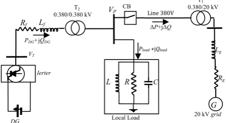
Fig. 1 shows the case study system which consists of a simple three-phase network with a grid connected DG system and a local load.
The DG is inverter based and connected to a 380V system through a 100 kVA transformer. The grid system is modeled by a 20 kV line to line voltage source with
125 MVA Short Circuit Capacity (SCC), which is connected to a 380V system using a 20 kV/0.380 kV, 100 kVA transformer and a 380V distribution line. The system parameters are presented in the Appendix.
Constant power control and constant current control are two mainly used control schemes in DG system. In the DG system which employs constant power control scheme, the active and reactive powers are controlled as constant. In the DG system which employs constant current control scheme, the current injected into the grid is controlled as constant. In this paper, distributed generation is modeled as a constant power with an interface control as proposed in [16]. The DG operates at unity power factor. The DG interface control variables are controlled in the d-q axis synchronous reference frame. Variables of d-q axis and DG interface control are used to calculate the modulation index and phase angle.
The load active and reactive power as function of voltage and frequency are expressed as follows [17]:
) 1 ( 0
0 VV k f
P
P P
p
Δ + ⎟ ⎠ ⎞ ⎜ ⎝ ⎛
= (1)
) 1
( 0
0 V k f
V Q
Q Q
q
Δ + ⎟⎟ ⎠ ⎞ ⎜⎜ ⎝ ⎛
= (2)
where V0 represents the system nominal voltage, p and q
are the voltage exponents of load active and reactive
powers, kP and kQ are frequency dependency factors of
active and reactive powers, ∆f is frequency deviation in
per-unit and P0 and Q0 represent the load active and
reactive powers corresponding to the nominal voltage.
The exponents p and q vary between 0 and 2 and, kP and
kQ can change from 0 to 3 and -0.2 to 0, respectively
[17].
3 ProposedIslandingDetectionMethod
In abnormal condition when the PCC voltage is in a range given in Table 1, the DG should be stopped to energize the power system within the clearing time as indicated in [18]. Clearing time is the time between the start of the abnormal condition and the DG ceasing to energize the power system. The purpose of the allowed
Fig. 1Grid connected DG system with local load.
VP CB
C
L R
Pload +jQload
PDG+jQDG
Lf
Rf
VT
Ierter
DG
T2
0.380/0.380 kV
20kV grid
ΔP+jΔQ
Lg
Rg
G
T1
0.380/20 kV
Line 380V
Local Load
Table 1 Response to abnormal voltages [9, 18, 20].
Voltage (at PCC) Maximum trip time
V < 50% 6 cycles 50% < V< 88% 120 cycles 88% <V<110% Normal operation 110% < V < 137% 120 cycles
V>137% 6 cycles
time delay is to ride through short-term disturbances to avoid excessive nuisance tripping [18]. Also, low voltage ride through (LVRT) algorithm is considered for DG unit to avoid low voltage tripping due to temporary short circuit or dip voltage [19].
In order to detect the islanding by U/O voltage relay, post-islanding PCC voltage should be decreased/increased less/greater than 0.88/1.1 of nominal voltage [20, 21]. In Fig. 1, if the active power exchange between the DG and grid system before islanding (ΔP) is small, the PCC voltage remains in the above mentioned limits and islanding cannot be detected.
As mentioned in the authentic references [9, 18, 20] loads with p=2 (parallel RLC) are the worst case for islanding detection. Therefore, the method is formulated for parallel RLC load.
The following equations can be used for determining the NDZ considering before and after islanding PCC voltages.
R V V R V P P P
P P
DG lBI l
2 0 2
0= = −Δ = =( +Δ ) (3)
R V P
P P
DG lAI
2 '
=
= (4)
where, VP and V'P are pre-and post-islanding PCC
voltages, respectively. Also, PlBI =Pl0, PlAI, PDG, ΔP and
R are pre- and post-islanding load active power, DG active power generation, active power exchange between DG and grid system and local load resistance,
respectively. In Eq. (3) V0 is the grid nominal voltage in
the 380 V transformer side and ∆V can be calculated as
∆V=∆IZ0, where Z0 is the Thevinen impedance of grid
seen from 380V transformer side. If reactive power of DG is equal to zero and load power factor is almost 1,
then ∆V can be written as follows:
0 0
VPZ
V≈Δ
Δ (5)
Substituting Eq. (5) into Eq. (3) and removing R between Eq. (3) and Eq. (4) and some manipulations, Eq. (6) can be written:
2 0
' 2 2 0
0
) (
) 1
( 1
V V V
PZ
P P
P DG
Δ + = Δ
− (6)
Using Eq. (3) and Eq. (4), the load active power can be calculated as Eq. (7).
' 2
0 2 0 P
lAI DG
V
P P or
P
V
= = 2 0
2 '
l P P
DG P
V V
P = (7)
Also, from Eq. (6), if Z0=0 (grid is considered as
infinity bus) the active power exchange between DG and grid can be calculated as follows:
(8) )
1
( '202
V V P P
P
DG −
= Δ
The NDZ can be obtained by substituting upper and
lower bounds of voltage ( 0
'/V
VP =1.1 and 0.88) into Eq.
(6); that results in the following inequality when Z0=0
[8, 10]:
355 . 17 % 132
. 29
% <Δ <
−
P P
DG (9)
It is important to note that, Eq. (9) is correct if the short circuit capacity of grid is assumed to be infinity
and V0=380 V, otherwise, NDZ should be calculated
from Eq. (6). If active power exchange between the DG and the grid is in the non-detection zone, the islanding phenomenon cannot be detected. To detect the islanding
phenomenon, Pref is determined adaptively based on the
values of DG generation and active power of local load. It is worth noting that the worst case of islanding detection happens when the power mismatch between the load active power and DG generation is almost zero. In such condition, there is no power exchange between the DG and the grid in nominal voltage. In order to
clarify the subject, suppose Pl =P0=PDG (ΔP=0) in
nominal voltage V0. Besides, suppose that the system
voltage changes to V1 due to non-islanding phenomena.
Then, Pl =P0(V1/V0)2 and ΔP=PDG(1−V12V02). In such
condition, if islanding occurs, the PCC voltage changes
from V1 to V0 after islanding. On the other hand, by the
conventional islanding detection method, islanding detection is not possible. But as the pre- and the post-islanding PCC voltage are not equal, it is possible that the islanding phenomenon occurs. Using the proposed method, the islanding will be detected even in such cases. In other words, the PCC voltage variation is
sensed by the voltage measurement and Pref switches
from Pref0 to a new Pref and as a result, the proposed
method drifts the voltage deviation to settle out the above mentioned limits, i.e. islanding is detectable.
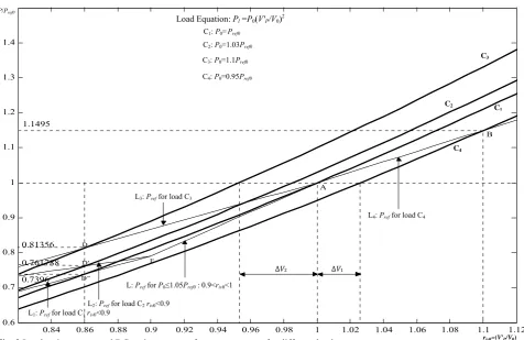
To explain the proposed method more precisely, refer to Fig. 2. In this figure, the load active power characteristic and DG active power reference are drawn
in respect to riv0=VP'/V0. The curves C1, C2, C3 and C4
are loads with P0=Pref0, P0=1.03Pref0, P0=1.1Pref0 and
P0=0.95Pref0, respectively.
By measuring the post-islanding PCC voltage and voltage deviation from nominal voltage, the curve of the
load active power in normal condition (P0) can be
determined. For instance, as shown in Fig. 2, if the
voltage deviation is equal to ΔV1>0, then, the load
active power curve is matched with curve C4. In this
Fig. 2 Load active power and DG active power reference versus riv0for different loads.
condition, Pref is determined as a linear function of
voltage that passes through point A(1, Pref0) and a point
like B. The riv0 of point B should be equal or greater
than 1.1. Therefore, the PCC voltage is deviated to point B in islanding condition. Since the islanding voltage ratio of this point is equal or greater than 1.1, the
islanding phenomenon will be detected. If riv0 of point B
is assumed to be 1.1, i.e. B(1.1, 1.21P0), the Pref is
determined as Eq. (10) for ΔV>0.
If the voltage deviation is ΔV2<0, then, the curve of
the load active power is fitted to the curve C3 with
P0=1.1Pref0, as shown in Fig. 2. In this condition, Pref is
determined as a linear function of voltage that passes
through points A(1, Pref0) and a point like D. The riv0 of
point D should be equal or less than 0.88. Therefore, the PCC voltage is deviated to point D in islanding condition. Since the islanding voltage ratio of this point is equal or less than 0.88, the islanding will be detected.
If the riv0 of point D is assumed to be 0.88, i.e. D(0.88,
0.7744P0), the Pref is determined as Eq. (11) for ΔV<0.
0 )
1 ( 1 . 0
21 . 1
0 0 0
0 − Δ >
+ − +
=P P P r V
Pref ref ref iv (10)
0 )
1 ( 12 . 0
7744 . 0
0 0 0
0 − Δ <
− +
=P P P r V
Pref ref ref iv (11)
Note that point B or point D should be the first point
of the intersection between Pref and Pload characteristics.
Additionally, these points should be stable ones, too.
The stability conditions of the operating points are discussed in Appendix A.1. For ΔV>0, point B is the
first intersection between Pref for any load that P0 is less
than Pref0. Also, because the slope of the Pl
characteristic at point B is greater than that of the Pref
characteristic, it is a stable operating point as explained in Appendix A.1.
Therefore, if islanding phenomenon occurs and ΔV is positive, the islanding will be detected. However, if islanding occurs and ΔV<0, the first stable intersection
point between Pref and Pload has a riv0 that is greater than
0.88 and also is a stable point for some loads. This
means that riv0 reaches to this stable point and settle, i.e.
the islanding is not detectable, and the NDZ of the method is not zero in islanding conditions.
To determine the NDZ of the method, the active load characteristic has been written as Eq. (12):
r P V V P
P l iv
P P l
l 2 0 2
'
0( ) =
= (12)
As mentioned before, for ΔV<0, the proposed method can detect islanding phenomenon if the first stable intersection point between curves Pl and Pref takes place at a point that riv0 is less than 0.88. This is possible if the slope of Pref is less than that of load curve at D(0.88, 0.7744P0). The slope of the load active power characteristic can be determined as follows:
0.84 0.86 0.88 0.9 0.92 0.94 0.96 0.98 1 1.02 1.04 1.06 1.08 1.1 1.12
0.6 0.7 0.8 0.9 1 1.1 1.2 1.3 1.4
1.1495
0.7396 D"
0.81356
0.761788 E
A
B
D' D
riv0=(V'P/V0) C1: P0=Pref0
C2: P0=1.03Pref0
C3: P0=1.1Pref0
C4: P0=0.95Pref0
Load Equation: Pl =P0(V'P/V0)2
C1
C3
C2
C4
ΔV1
ΔV2
L3: Pref for load C3
L: Pref for P0≤1.05Pref0 : 0.9<riv0<1
L2: Pref for load C2riv0<0.9
L4: Pref for load C4
L1: Pref for load C1riv0<0.9 P/Pref0
0 0 2
0 0 0.88 0 0 0.88
( ) 2 1.76
iv iv
iv r iv r
iv
d
P r P
P r
dr = = = = 0 (13)
In order to detect the islanding, the slope of the
active power load at point that has riv0=0.88 should be
greater than that of Pref .
P P
or P P
P0 ref0 0.12 0 0 1.0146 ref0
7744 . 0 76
.
1 > − > (14)
Then, for P0≤1.0146Pref0, the islanding phenomenon
is not detectable by the method. In other words, the NDZ of the proposed method is as follows:
0 1.46%
DG
P P
Δ
≤ ≤ (15)
The Pref that is shown in Eq. (11) cannot detect the
islanding phenomenon for P0<1.0146Pref0. In order to
reduce the NDZ to zero, the Pref is determined as two
linear functions of voltage for P0<aPref0 which a is a
coefficient and should be greater than 1.0146. As
previously mentioned, for load with P0<1.0146Pref0, Pref
as defined in Eq. (11) intersects the load curve at two
points. The riv0 of the first point is greater than 0.88 and
is stable; the riv0 of the second point is less than 0.88 and
is an unstable operating point. Therefore, the PCC voltage decreases and reaches to the stable operating
point (riv0>0.88) in islanding condition. If a is greater
than 1.0146, the riv0 of the intersection points of the
load curve and Pref are less than 0.88; the first point that
has a greater riv0 is stable operating point and the other
one is unstable. Note that if a is a little greater than 1.0146, these two points are near together. Therefore, because of the transient behavior of islanding
phenomenon, riv0 may pass through the riv0 of the
unstable operating point. In other words, instability will occur in the PCC voltage. Simulation results show that if a is selected 1.05 or greater, the PCC voltage will be settled in the stable intersection point and then instability will not occur. Also for detecting the
islanding phenomenon with high reliability, riv0 of point
D can be selected less than 0.88 (for instance 0.86, as it
is specified in Fig. 2). In this case, Pref for ΔV<0 and
P0>1.05Pref0, which is defined in Eq. (11), will change
to Eq. (16).
0 V ) 1 ( 14 . 0
7396 . 0
0 0 0
0 − Δ <
− +
= ref ref iv
ref r
P P
P
P (16)
In order to reduce the NDZ to zero, Pref is selected
as piecewise linear function of voltage for
Pref0<P0<1.05Pref0; the first section of Pref for loads that
Pref0<P0<1.05Pref0 is determined in such a way that
passes through A(1, Pref0). The slope of this line (i.e. m)
at point A should be greater than that of the load curve
at this point (m>2P0). In this situation the operating
point of A is unstable in islanding condition as
discussed in Appendix A.1. If m takes 2.1 P0, the first
section of Pref for P0≤1.05Pref0 is determined as Eq. (17).
Point E along this section of Pref is determined in such a
way that the first intersection point of the second section
of Pref with load active power curve passes through
point like D'; the riv0 of D' should be greater than or
equal to o.88. Point E is not unique and a lot of points can satisfy the above condition. In other words, the above condition can be satisfied if point E is on line L
and 0.88<riv0<0.95. For example, if the riv0 of point D' is
assumed to be 0.88 and E is selected with riv0=0.9, the
line that passes through points E and D' is formulated as Eq. (18).
Pref=2.1Pref0(riv0-1)+Pref0 (17)
0 0
0
0 ( 0.9) 0.79
02 . 0
7744 . 0 79 . 0
ref iv
ref
ref r P
P P
P = − − + (18)
where 0.9<riv0≤1 and riv0<0.9 in Eqs. (17) and (18),
respectively.
Note that if point D' (as shown in Fig. 3) is selected
as D' (0.86, 0.7396P0), Eq. (18) changes to Eq. (19) for
riv0<0.9.
0 0
0
0 ( 0.9) 0.79
04 . 0
7396 . 0 79 . 0
ref iv
ref
ref r P
P P
P = − − + (19)
In Fig. 2, line L which is drawn as Eq. (17) is the
first section of Pref for loads that their active powers are
between Pref0 and 1.05Pref0. The second section of Pref is
line L1 for curve C1 which is drawn as Eq. (19).
Therefore, if Pref is determined as Eq. (10) for
P0<Pref0, Eq. (16) for P0>1.05Pref0 and Eq. (17) and Eq.
(19) for Pref0<P0<1.05Pref0, the NDZ of the proposed
method reduces to zero. In fact, the NDZ is only one
point in which P0 is exactly equal to PDG. Note that, the
slope of line L is only dependent on Pref0 for loads that
satisfy the inequality Pref0<P0<1.05Pref0. For example, in
Fig. 2, lines L and L2 are Pref for load C2
(P0=1.03Pref0<1.05Pref0) in which line L2 passes through
point E on line L and point D"(0.86, 0.7396P0) on curve
C2. Line L3 is Pref for load C3 that passes through points
A and D. Also, line L4 is Pref for load C4 that passes
through A and B.
In order to determine the equation of Pref, first, the
load active power in nominal voltage (P0) should be
calculated. If islanding phenomenon occurs, the post-islanding PCC voltage is different from the pre-islanding PCC voltage, depending on the difference
between the DG active power generation (PDG=Pref0)
and the local load active power ΔP. Equation (20) will
result by substituting riv0 in Eq. (7):
r P
PDG= ref0= iv2 Pl0=riv20P0 or 2
0 0 0
iv ref r P
P = (20)
In normal condition, if the PCC voltage does not
vary, then riv=1 and Pl0=Pref0. However, if the voltage
varies, then riv≠1 and P0 and Pl0 can be computed from
Eq. (20).
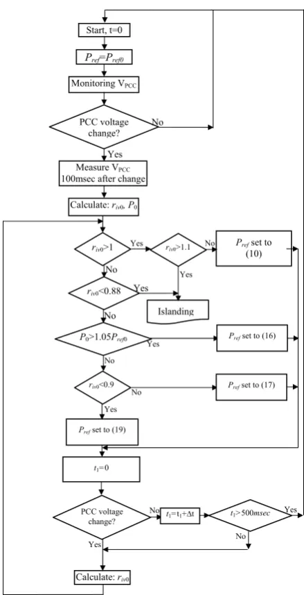
In the proposed method, when the active power imbalance between DG and the local load in nominal voltage is high enough that the voltage deviation in post-islanding is less/more than U/O voltage relay settings, the islanding is detected by this relay. On the other hand, when the active power imbalance is low, application of the proposed method is highlighted. So, in the simulation results which are presented in the next section, some cases are considered in which the power exchange between the DG and the grid satisfies inequality (9). The flowchart of the proposed method is shown in Fig. 3.
Based on Eq. (1), at the nominal system frequency
and voltage, the active power of the load is P0. When
the system frequency is changed the load active power will be changed too, and in nominal voltage, it is equal to P0(1+kpΔf). As mentioned earlier, the method has
been formulated for kp=0. The active power reference
(Pref) formula is a function of Pref0, riv0 and P0.
WhenkP=0, the value that is computed from Eq. (20) is
P0. However in condition that kp≠0, the computed value
will be equal to P0(1+kpΔf). Regardless of the value of
kP, the method uses the computed value of Eq. (20) for
determining the active power reference of DG. In other words, the method formulation is irrelevant to the value
of kP. In general, if the voltage change is sensed, the
active power reference will be switched from Pref0 to the
new designed Pref. Then, islanding phenomenon is
detected if it takes place.
It is generally accepted that the parallel RLC load (p=2) which has a high quality factor and operates at resonance condition (unity power factor) is the worst case for islanding detection [9, 18, 20]. Therefore, in the simulation results, the DG is designed to operate at unity power factor and the local load is modeled as a constant RLC load.
4 EvaluationoftheProposed Method
In abnormal conditions, the voltage variation has a transient behavior. When the voltage deviation is sensed by the voltage measurement equipment and the relay, a little time is required until the voltage reaches to a new stable value. Various simulations in different conditions show that a delay of 100 msec is sufficient for this purpose in islanding conditions. Therefore, in simulation results, the PCC voltage will be considered
as post-islanding PCC voltage and is denoted by V'P0,
100msec after sensing of voltage changes. Also, the
islanding voltage ratio in this situation (riv0=V'P0/V0) is
named riv01. Using measured data (V'P0, riv01), P0 will be
calculated from Eq. (20). Therefore, the active power
reference of DG is determined as Eq. (10) for P0<Pref0
(ΔV>0) and as Eq. (16) for P0>1.05Pref0 (ΔV<0). Also, it
is determined as Eq. (17) and Eq. (19) for P0≤1.05Pref0,
dependent on riv0. In order to evaluate the proposed
method, islanding and non-islanding conditions are simulated. In non-islanding phenomena, if the proposed
Fig. 3 The flowchart of the proposed islanding detection
method.
method is used and the PCC voltage changes, the DG active power generation changes according to Eq. (10), Eq. (16), Eq. (17) and Eq. (19). In such cases, if the PCC voltage stays between the thresholds and remains
stable for more than 500msec, the Pref of DG can change
into initial setting (Pref0). The obtained results are
presented and discussed in the following subsections.
4.1 Islanding Conditions
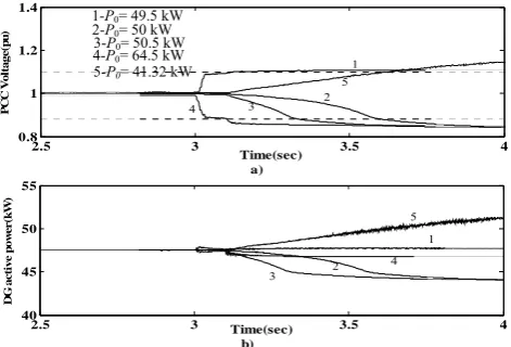
The proposed method is implemented on the study system shown in Fig. 1. The islanding phenomenon occurs at t=3 sec. The DG active power generation
(PDG) is considered to be 50 kW while the local load is
assumed to have different values like 50 kW (fully matched), 49.5 kW and 50.5 kW (a little mismatch), 64.5 kW (lower bound of U/O voltage relay setting or
Calculate: riv0
No
riv0>1
riv0<0.88
P0>1.05Pref0
riv0<0.9
riv0>1.1 Prefset to (10)
Islanding
Yes
No Yes
No
No
Yes
Yes
No
No
Yes
Prefset to (16)
Prefset to (17)
Prefset to (19)
t1=0
t1>500msec
Yes
Start, t=0
Monitoring VPCC
Pref=Pref0
Measure VPCC 100msec after change
PCC voltage change?
Calculate: riv0, P0
PCC voltage change?
Yes No
t1=t1+∆t Yes
No
ΔP=0.2913PDG), 41.32kW (upper bound of U/O voltage
relay setting or ΔP = 0.17355PDG) at nominal voltage.
Note that kP and kQ are considered to be zero in the
simulation results.
If Pload is assumed to be 50kW in nominal voltage
(380 V) and islanding phenomenon occurs, then before voltage deviation and 100msec after that, the PCC voltage is equal to 379.949V and 378.217V,
respectively. The riv01 and P0 can be computed and are
equal to 0.997 and 50.25kW, respectively. The P0 is less
than 1.05Pref0 and then Pref should be determined from
Eq. (17) until riv0≥0.9, and from Eq. (19) when riv0≤0.9.
For different load active powers, riv01, P0 and Pref are
calculated and summarized in Table 2.
The variation of PCC voltage and DG active power using the proposed method for loads in Table 2 (50, 50.5, 64.5, 49.5 and 41.32 kW) are depicted in Fig. 4. If the proposed method is not used, the PCC voltage
variations will not be enough to detect islanding (riv01 in
Table 2 less than 1.1 or greater than 0.88) for local loads that inequality (9) is satisfied. However, by using the proposed method, the voltage variations are enough for U/O voltage relay to detect the islanding phenomenon, which is shown in Fig. 4. Also, the DG active power variation is zero if the proposed method is not used. However, if the proposed method is used, the DG active power variation depends on the PCC voltage. The DG active power decreases or increases until the PCC voltage exceeds from U/O voltage relay thresholds.
It can be shown from Fig. 4 that using the proposed method, the post-islanding voltage variations are about 0.88/1.1 of the PCC nominal voltage for any loading conditions and the over voltage is not high. Note that all of the above simulation results show that islanding phenomenon is detected by the presented technique at the permitted time.
Fig. 5 shows the PCC voltage for different active
power load voltage exponent (p) and Pload=Pref0=50 kW
with Qf =2.5. It is shown that the islanding detection for
p =0 and 1 is much simpler and faster than that of p =2. This is due to the fact that as the p for local load decreases, the PCC voltage deviation from nominal value increases more in islanding condition. In Fig. 6 the performance of the proposed method is shown for
non-zero kP (kP=3) and it is compared with kP=0. The
resonance frequency of the local load (fr) is considered
to be 60.4 and simulations are done for P0=50kW and
49kW (P0=49kW is the worst case of islanding
detection for kP=3 and fr=60.4Hz when the DG
Table 2 Determining Preffor different loading cases.
Ca ses
Pload
(kW) VP V'P0 riv01
P0
(kW) Pref (kW)
1 50 379.9 379.0 0.9975 50.2 58.4riv0-13
2 50.5 379.8 377.4 0.9932 50.6 50.3riv0-5.76
3 64.5 376.4 336.0 0.8843 63.9 19.33riv0+30.
4 49.5 380.0 380.8 1.0022 49.7 102.3riv0-52.3
5 41.3 381.8 414.8 1.0918 4.19 7.54riv0+42.5
generation is 50 kW). For different p and kP, riv01 and P0
are calculated and summarized in Table 3; Pref for these
cases will be calculated as explained in section 3. P0 in
the cases 1 to 6 are less than 1.05 Pref0 and greater than
Pref0, therefore, Pref is piecewise linear function of
voltage for these cases which is determined from Eq.
(17) as 105riv0-55 for riv0≥0.9 and from Eq. (19) for
riv0≤0.9 that are shown in Table 3.
For case 5 of Table 3, load active power is 49 kW in nominal voltage and frequency, but 100msec after islanding; its calculated value is 50.3kW. This value is
equal to P0 for case 3. This can be seen in curves 2 and
3 of Fig. 6 that islanding is detected almost in the same time for these cases after islanding. On the other hand, because of the load frequency dependency, the case 5 in Table 3 is also the worst case for islanding detection, as case 3.
Fig. 5 PCC voltage in islanding condition for p = 0, 1 and 2, kP
= 0 and Pload = 50 kW
Fig. 6 PCC voltage in islanding condition for p = 2, kP = 0, 3
and P0 = 50, 49 kW
2.5 3 3.5 4
0.4 0.6 0.8 1
Time(sec)
PCC Vo
lt
a
g
e
(p
u
)
2.5 3 3.5 4
0.8 1 1.2 1.4
Time(sec)
P
C
C V
o
lt
a
g
e
(pu)
Fig. 4 Evaluation of the proposed method for different loadings:
(a) PCC voltage and (b) DG active power.
2.5 3 3.5 4
0.8 1 1.2 1.4
Time(sec) a)
PCC Vo
lt
a
g
e
(p
u
)
2.5 3 3.5 4
40 45 50 55
Time(sec) b)
DG
a
c
ti
v
e
p
o
we
r
(k
W
)
3 2
4 1 5
4 3
1
2 5
p=2
p=1 p=0
1 P0=50kW and kP=3
2 P0=49kW and kP =3
3 P0=50kW andkP=0
4 P0=49kW andkP =0
1 2
3 4
3-P0= 50.5 kW 5-P0= 41.32 kW
1-P0= 49.5 kW 2-P0= 50 kW 4-P0= 64.5 kW
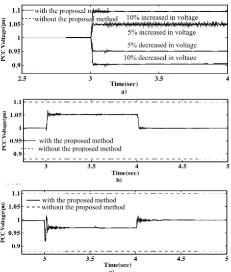
4.2 Non-islanding Conditions
In this section the performance of the proposed method has been tested on the system under study in non-islanding phenomena. The load is a 50 kW RLC load. The phenomena like system voltage variation, capacitor bank switching and variation of local load have been considered. Results of the examining of the phenomenon are presented in Fig. 7. The Fig. 7(a) shows the PCC voltage variation when the system voltage decreases and increases 10% and 5% at t=3sec as a step function, whether the proposed method is used
or not. The voltage deviation is sensed, then Pref,
switches to the determined Pref at t=3.1sec, as mentioned
above. Fig. 7(b) shows the curve of the PCC voltage variation for capacitor switching; at t=3sec a 400μF capacitor bank (21.78 kVAr) has been paralleled to the local load and at t=4sec it is switched off. At t=3sec the
voltage variation has been sensed, therefore Pref changes
from Pref0 to the determined Pref at t=3.1sec. The PCC
voltage deviation is not enough for islanding detection
and also it is constant; after 500 msec, Pref jumps to
Pref0. At t=3sec, because of the capacitor bank switching
off, another voltage deviation is sensed; after 100msec,
Pref is switched to a new one. The simulation is done in
condition whether the proposed method is used or not. Also, Fig. 7(c) illustrates the results when another 50
kW load with Qf =1.8 is switched on in parallel with the
existing load at t=3sec and switched off at t=4sec. Note
that, Pref changes like capacitor bank switching case, at
t=3.1sec, t=3.5sec and t=4.1sec. In Table 4 riv01, V'P0 and
Pref are calculated and summarized for non-islanding
conditions.
The simulation results in non-islanding conditions show that in all cases (decreasing or increasing of system voltage, switching the capacitor bank and load), only operating point has been changed and the condition has not been detected as islanding. It can be seen from
Fig. 7 that there is a small difference on the PCC voltage variation in the condition that the proposed method is used or not. However, because the DG active power reference depends on the PCC voltage, the impact of the proposed method on the DG active power generation is significant. So, if the PCC voltage changes, DG active power generation changes too. If necessary, the DG active power generation can be returned to the previous setting.
4.3 Effects of Load Quality Factor on the Performance of the Proposed Method
Quality factor (Qf) is an important parameter in the
islanding detection behavior techniques. Therefore, this has been mentioned in different references. For
instance, it is emphasized that for loads with Qf less than
1.8, the islanding should be detected in less than two seconds [10, 18, 20-22]. In fact, islanding detection is
difficult for the load with high Qf [10]. Also based on
IEEE Std. 929, the islanding should be detected in case
of the loads with Qf less than 2.5 [18]. In addition, the
applied method should be capable to detect the islanding
for loads with Qf greater than 0.5, as stated in [23]. In
this paper, in order to investigate the performance of the
proposed method, different load quality factors have
been considered. Islanding phenomenon is simulated for
50 kW load active power and different Qf like 0.5, 1.5,
2.5 and 4. In these conditions, riv01, P0, VP, V'P0 and Pref
are calculated and presented in Table 5. For cases of
Table 5, Pref has been calculated from Eq. (19) until
riv0≥0.9 and from Eq. (21) when riv0<0.9. Fig. 8 shows the simulation results. It can be seen that for all considered quality factors, islanding phenomenon is detected at the permitted time.
Table 4 Determining Preffor non-islanding conditions.
Cases Conditions VP V'P0 riv01 P0 (kW) Pref (kW)
1 5% increase in system voltage 379.613 397.765 1.0467 45.6 52.2riv0-2.16
2 10% increase in system voltage 379.613 416.731 1.097 41.6 3.36riv0+46.6
3 5% decrease in system voltage 379.613 361.86 0.952 55.1 65.8riv0-15.83
4 10% decrease in system voltage 379.613 343.119 0.9029 61.3 33.1riv0+16.9
5 400 µF capacitor switch on at t=3sec 379.613 400.381 1.0536 45 45riv0+5.03
6 400 µF capacitor switch off at t=4sec 398.891 379.613 0.999 50.1 61.1riv0-15.5
7 50kW load switched on at t=3sec 379.613 368.927 0.971 53 76.9riv0-26.9
8 50kW load switched off at t=4sec 368.927 379.458 0.9986 50.1 51.9riv0-7.2 Table 3 Determining Pref for different p and kP.
Cases fr(Hz) Qf Pload (kW) VP V'P0 riv01 P0 (kW) Pref0(kW)
1 (p=0, kp=0) 60 2.5 50 379.63 377.32 0.993 50.7 50.057riv0-5.551
2 (p=1, kP=0) 60 2.5 50 379.63 378.33 0.996 50.4 55.604riv0-10.544
3 (p=2, kP=0) 60 2.5 50 379.63 378.75 0.997 50.3 57.453riv0-12.208
4 (p=2, kP=3) 60.4 2.5 50 378.54 375.21 0.987 51.2 40.812riv0-2.769
5 (p=2, kP=3) 60.4 2.5 49 378.16 378.85 0.997 50.3 59.302riv0-13.8718
6 (p=2, kP=0) 60.4 2.5 50 378.54 378.05 0.995 50.5 53.755riv0-8.88
7 (p=2, kP=0) 60.4 2.5 49 378.16 381.64 1.0043 49.6 100.16riv0-50.16
Fig. 7 Evaluation of the proposed method for non-islanding
conditions: (a) system voltage change, (b) capacitor switching and (c) load switching.
Fig. 8 Effect of load quality factor on the performance of the
proposed method.
Table 5 Determining Pref for different Qf when Pload is equal to 50kW.
Cases Qf VP V'P0 riv01 P0 (kW) Pref (kW)
1 0.5 379.908 379.388 0.998 50.16 60riv0 - 14.5
2 1.5 379.579 378.782 0.997 50.3 57riv0 - 11.8
3 2.5 379.96 378.799 0.9968 50.3 57riv0 - 11.8
4 4 380.358 378.54 0.9962 50.4 55.8riv0 -
10.7
4.4. Comparing with the Presented Technique in [8]
In this subsection the proposed method is compared with the presented technique in [8]. As mentioned in Table I of [8], the NDZ of the presented method is not zero. Two cases are considered for simulations; first, the active power reference of DG is demonstrated by a linear function of the PCC voltage as described in
reference [8] (Pref =0.1riv0-0.05). Then, another case is
considered where Pref is determined by the proposed
method in section 3. Simulation results show that the NDZ of the presented method in [8] is approximately
2.5 3 3.5 4 4.5 5 5.5 0.8 0.9 1 1.1 1.2 1.3 PCC V ol tag e(p u )
2.5 3 3.5 4 4.5 5 5.5 0.8 0.9 1 1.1 1.2 1.3 PCC V ol tag e(p u )
2.5 3 3.5 4 4.5 5 5.5 0.8 0.9 1 1.1 1.2 1.3 Time(sec) P CC V ol tag e( pu )
2.5 3 3.5 4 4.5 5 5.5 0.8 0.9 1 1.1 1.2 1.3 Time(sec) P CC V ol tag e( pu )
c) P0=49.8kW d) P0=49.9kW
Fig. 9 Comparing the proposed method with the presented
method in [8].
between 49.68 kW and 49.95 kW. The active power
generation of DGis assumed to be 50 kW, while local
load is considered in the NDZ of [8] with Qf =1.8 and
islanding simulation will be done for two mentioned cases. Fig. 9 illustrates the results when islanding phenomenon occurs at t=3 sec. It is evident that the presented method in [8] is failed; meanwhile, islanding is detected by the proposed method in all loading conditions.
5 Conclusion
In this paper a new islanding detection technique for inverter based DG is presented. The method is based on the change in DG active power reference and is an
adaptive one. If the PCC voltage does not change, Pref is
equal to Pref0. If the PCC voltage changes, the Pref will
change, too. The Pref is determined adaptively by
computing load active power and post-islanding PCC voltage. The DG active power reference is determined as a linear function of PCC voltage. When islanding phenomenon occurs, the proposed method reaches the PCC voltage to the upper or lower thresholds of the U/O voltage relay. The proposed method does not have any NDZ. If the PCC voltage is changed due to non-islanding phenomena, the effect of the proposed method in voltage variation will be almost zero. Also, the proposed technique is reliable, i.e. it detects islanding when it is and it does not detect when it is not. The effectiveness of the proposed algorithm is demonstrated by simulation results. In addition, it is shown that for all cases, islanding phenomenon is detected at the permitted time.
Appendix
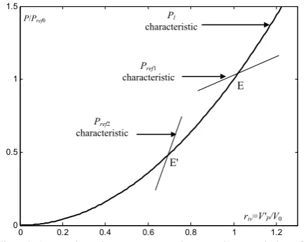
A.1 Stability Conditions of the Operating Point
If the slope of the load characteristic (Pl) at the
operating point is greater than that of the load active
power reference (Pref), this point will be a stable
operating point. Also, if the slope of Pl at the operating
point is smaller than that of the Pref, this point is
unstable. More details can be found in Fig. A.1.
2.5 3 3.5 4
0.9 0.95 1 1.05 1.1 Time(sec) a) PCC V o lt a g e (p u ) 0 054
3 3.5 4 4.5 5
0.9 0.95 1 1.05 1.1 Time(sec) b) P CC Vo lt a g e (p u )
3 3.5 4 4.5 5
0.9 0.95 1 1.05 1.1 Time(sec) c) PCC V o lt a g e (pu )
2.5 3 3.5 4
0.8 0.9 1 1.1 1.2 Time(sec) ) P C C Vo lt a g e (p u )
a) P0=49.68kW b) P0=49.7kW
10% increased in voltage
10% decreased in voltage 5% increased in voltage 5% decreased in voltage
4
1
2, 3
1-with the presented method in [8]
2-with the proposed method 2
1 2 1 2 1 1 2
with the proposed method without the proposed method
with the proposed method without the proposed method
with the proposed method without the proposed method
1-Qf = 0.5
2-Qf =1.5
3-Qf= 2.5
4-Qf= 4
0 0.2 0.4 0.6 0.8 1 1.2 0
0.5 1 1.5
P (MW)
Fig. A.1 Load active power and Pref characteristics for showing the stability condition of the operating points.
Suppose Pref1 is the Pref characteristic. The slope of
the load characteristic is greater than that of the Pref
characteristic at point E, then, this point is a stable operating point. For showing the stability of point E, suppose this point to be the operation point and a small positive deviation takes place in voltage. Therefore, in
this case Pl>Pref, Pl is decreasing to reduce the
difference between Pl and Pref. In order to decrease Pl,
voltage should decrease, too. It means that for positive voltage deviation, operating point will come back to point E.
The same procedure will be applied if the voltage deviation is negative. Hence, it can be concluded that
point E in Fig. A.1 is stable. On the other hand, if Pref2 is
the Pref characteristic at point E', the slope of the load
characteristic is smaller than that of the Pref
characteristic. Therefore, this point is an unstable operating point. For showing the instability of point E', suppose this point to be the operating point and a small positive deviation take place in voltage. Therefore, in
this case Pl <Pref, Pl is increasing to reduce the
difference between Pl and Pref. In order to increase the
Pl, voltage should increase too. It means that operating
point will have more deviation from E'. The same procedure will be applied if the voltage deviation is negative. Thus, point E' is an unstable operating point.
A.2 System Parameters
The parameters of the grid system, line and transformer are presented in Tables A-1 and A-2.
Table A-1 Parameters of the grid system. Nominal voltage 380 V System frequency 60 Hz Internal resistance 0.06 Ohm Internal inductance 0.9 mH
Table A-2 Line and transformer characteristics. 380V line reactance 0.2734Ω 380V line resistance 0.05937 Ω Transformer short circuit impedance 4%
References
[1] IEEE Standard for interconnecting distributed
resources with electric power systems, 1547-2003, Jul. 2003.
[2] Salman S. K., Kin D . J. and Weller G., “New
loss of main detection algorithm for embedded generation using rate of change of voltage and changes in power factors”, Developments in Power System Protection, IEEE Conference, Amesterdam, pp. 82-85, Apr. 2001.
[3] Refern M. A., Usta O. and Fielding G.,
“Protection against loss of utility grid supply for a dispersed storage and generation unit”, IEEE Trans. on Power Del., Vol. 8, No. 3, pp. 948-954, Jul. 1993.
[4] Ropp M., Aaker K., Haigh J. and Sabhah N.,
“Using power line carrier communications to prevent islanding”, Proc. 28th IEEE Photovoltaic Specialist Conference, Anchorage, Ak, pp. 1675-1678, Sep. 2000.
[5] Xu W., Zhang G., Li C., Wang W., Wang G. and
Kliber J., “A power line signaling based technique for anti-islanding protection of distributed generators-part I: scheme and
analysis”, IEEE Trans. on Power Del., Vol. 22,
No. 3, pp. 1758-1766, Jul. 2007.
[6] Wang W., Kliber J., Zhang G., Xu W., Howell B.
and Palladino T., “A power line signaling based scheme for anti-islanding protection of distributed generators -part II: field test results”, IEEE Trans. on Power Del., Vol. 22, No. 3, pp. 1767-1772, Jul. 2007.
[7] Mahat P., Chen Z. and Bak-Jensen B., “A hybrid
islanding detection technique using average rate of voltage change and real power shift”, IEEE Trans. on Power Del., Vol. 24, No. 2, pp. 764-771, Jul. 2009.
[8] Zeineldin H. H. and Kirtley J. L., “A simple
technique for islanding detection with negligible non-detection zones”, IEEE Trans. on Power Del., Vol. 24, No. 2, pp. 779-786, Apr. 2009.
[9] Bower W. and Ropp M., “Evaluation of
islanding detection methods for photovoltaic utility interactive power systems”, Int. Energy Agency Implementing Agreement on Photovoltaic stems, Tech. Rep. IEA PVPS T5-09, Mar. 2002.
[10] Hernandez-Gonzalez G. and Iravani R., “Current
injection for active islanding detection of electronically-interfaced distributed resources”, IEEE Trans. on Power Del., Vol. 21, No. 3, pp. 1698-1705, Jul. 2006.
[11] Ma T.T., “Novel voltage stability constrained
positive feedback anti-islanding algorithm for the inverter-based distributed generator systems”, IET Renew. Power Gener., Vol. 4, No. 2, pp. 176-185, Mar. 2010.
P/Pref0
E'
E
riv=V'P/V0
Pref1 characteristic
Pref2 characteristic
Pl
characteristic
[12] Liu F., Kang Y., Zhang Y., Duan S. and Lin X., “Improved SMS islanding detection method for
grid-connected converters”, IET Renew. Power
Gener., Vol. 4, No. 1, pp. 36-42, 2010.
[13] Smith G. A., Onions P. A. and Infield D. G.,
“Predicting islanding operation of grid connected PV inverters”, Proc. IEE Electric Power Applications, Vol. 147, No. 1, pp. 1-6, Jan. 2000.
[14] Kunte R. S. and Wenzhong G., “Comparison and
review of islanding detection techniques for distributed energy resources”, 40th North American Power Symposium (NAPS '08), Calgary, AB, pp. 1-8, Sep. 2008.
[15] Velasco D., Trujillo C. L., Garsera G. and
Figueres E., “Review of anti-islanding techniques in distributed generators”, Renewable and Sustainable Energy Reviews, Vol. 14, No. 6, pp. 1608-1618, Aug. 2010.
[16] Wang X., Freitas W., Xu W. and Dinavahi V.,
“Impact of DG interface controls on the sandia frequency shift anti-islanding method”, IEEE Trans. on Energy Convers., Vol. 22, No. 3, pp. 792-794, Sep. 2007.
[17] Kundur P., Power System Stability and Control,
McGraw Hill Inc., Newyork, 1994.
[18] IEEE Recommended practice for utility interface
of photovoltaic systems, IEEE Standard 929-2000.
[19] Tsili M. and Papathanassiou S., “A review of
grid code technical requirements for wind
farms,” IET Renewable Power Generation, Vol.
3, No. 3, pp. 308-332, Sep. 2009.
[20] UL 1741 Standard for Static inverter and charge
controllers for use in photovoltaic systems, UL 1741 Standard, 2001.
[21] UL 1741 Standard for Converters and controllers
for use in independent power systems, UL 1741Standard, 2001.
[22] Schauder C. and Mehta H., “Vector analysis and
control of advanced static VAR compensators”, Proc. Inst. Elect. Eng., Vol. 15, No. 3, pp. 299-306, Jul. 1993.
[23] Woyte A., Belmans R. and Nijs J., “Testing the
islanding protection function of photovoltaic
inverters”, IEEE Trans. on Energy Convers.,
Vol. 18, No. 1, pp. 157-162, Mar. 2003.
Ebadollah Kamyab was born in
Larestan, Iran. He received the B.Sc. and M.Sc. both from Ferdowsi University of Mashhad, Mashhad, Iran. He served as a high voltage Electrical Engineer at the Khorasan Regional Electric Company, Mashhad, Iran from 1992. Since 2007 he has been studying toward his Ph.D. degree at Ferdowsi University of Mashhad, Mashhad, Iran. His research interests are Distributed Generation, Power System Protection and Transformer.
Javad Sadeh was born in Mashhad, Iran
in 1968. He received the B.Sc. and M.Sc. with honour both in Electrical Engineering from Ferdowsi University of Mashhad, Mashhad, Iran in 1990 and 1994, respectively and obtained his Ph.D. in Electrical Engineering from Sharif University of Technology, Tehran, Iran with the collaboration of the electrical engineering laboratory of the Institut National Polytechnique de Grenoble (INPG), France in 2001. He is currently an associate professor in the Department of Electrical Engineering at Ferdowsi University of Mashhad, Mashhad, Iran. His research interests are Power System Protection, Dynamics and Operation.
![Table 1 Response to abnormal voltages [9, 18, 20].](https://thumb-us.123doks.com/thumbv2/123dok_us/213874.2015806/3.595.81.254.97.159/table-response-to-abnormal-voltages.webp)