Please cite this article as: H. Zivarian, M. Soleimani, M. H. DoostMohammadi, Field Programmable Gate Array–based Implementation of an Improved Algorithm for Objects Distance Measurement, International Journal of Engineering (IJE), TRANSACTIONS A: Basics Vol. 30, No. 1, (January 2017) 57-65
International Journal of Engineering
J o u r n a l H o m e p a g e : w w w . i j e . i rField Programmable Gate Array–based Implementation of an Improved Algorithm
for Objects Distance Measurement
H. Zivarian, M. Soleimani, M. H. DoostMohammadi*
Department of Electrical Engineering, Hamedan University of Technology, Hamedan, Iran
P A P E R I N F O
Paper history: Received 02 October 2016
Received in revised form 20 November 2016 Accepted 28 December 2016
Keywords: Distance measurement image processing
field programmable gate array implementation
machine vision
A B S T R A C T
In this work, the design of a low-cost, field programmable gate array (FPGA)-based digital hardware platform that implements image processing algorithms for real-time distance measurement is presented. Using embedded development kit (EDK) tools from Xilinx, the system is developed on a spartan3 / xc3s400, one of the common and low cost field programmable gate arrays from the Xilinx Spartan family. Latency of the hardware is less than 100μs in 5000 clock cycles with 50MHz maximum frequency which is way less than MATLAB software performance about 82ms. Simulation and experimental results clearly indicate the potential of the presented FGPA-based platform for real-time distance measurement of images acquired from our camera setup. Thus, this platform can be used in any system with the needs of real-time or semi real-time machine vision.
doi: 10.5829/idosi.ije.2017.30.01a.08
1. INTRODUCTION1
Assertive technology has always been demanded for machines and robots in industry and basic technology. One of the most important demands is to enhance the intelligent vision of these systems. However, with the advancement of technology, the development of such devices has been possible, and of course, fundamental. Also in this field, the real-time imaging under dynamic conditions is very important. Given this scenario, the smart vision of mechanized robots is one of the most important factors to consider in today's industry. For example, this is very important to know the distance of the obstacles around the robot in a chemical plant or a sensitive production line of a factory.
Some efforts have been made to develop these devices, to equip these robots with virtual vision, and making them informed of more environmental information. Most of these new tools to achieve this goal are based on ultrasound technology. Wu et al. used sonar system together with some filtering method to
1*Corresponding Author’s Email:[email protected] (M. H. DoostMohammadi)
detect objects on seafloor with appropriate resolution [1]. Fei-yu also used sonar system to measure obstacle distance [2]. Unfortunately in most cases, the distance measured by these devices and their response time in some applications, is not accurate and fast enough. Improvement of these systems with the high
measurement accuracy and the appropriate
accountability, entails costly measures. Chang et al. presented an ultrasonic devices for distance measurement which was fabricated and test to improve the distance measurement limitation [3]. Kim et al. presented a new distance measurement method with the use of a single camera and a rotating mirror. A camera in front of a rotating mirror acquires a sequence of reflected images, from which distance information is extracted [4]. Rahman et al. proposed a novel distance measuring system based on eye-distance. The distance between centers of two eyes is used for measuring the person to camera distance [5]. Mohammad used the infrared (IR) together with ultrasonic (US) sensors to improve the overall vision systems of mobile robots [6]. Xiaoming et al. proposed a real-time method which can measure distance using a modified camera. This method can only be performed within 3.21ms to achieve
acceptable accuracy [7]. Shrivastava et al. presented a distance measurement of an obstacle using separate ultrasonic transmitter, receiver and a P89C51RD2 microcontroller [8]. Jinjin et al. introduced a single bit cross correlation method to improve the range resolution of the ultrasonic distance measurement [9].
The accuracy of these works are good but not acceptable enough when accurate calculation of distance is needed. Therefore, in this paper, we are looking for an accurate implementation of a distance measuring system which can be used as a part of robot vision. One of the reasons is that embedded image processing is usually used in various industrial applications in computing platforms. Nowadays, one of the efficient platforms for implementing algorithm is the FPGA platform. FPGA-based implementation of various systems have been done in different literatures. Mekhilef and Rahim presented a FPGA-based implementation of the regular symmetric sampled three-phase PWM inverter waveform [10]. Yuan investigated the possibility and effectiveness of multi-mode vibration control of a plate through real-time FPGA implementation [11]. Mandal and Mishra proposed a FPGA-based pipelined CORDIC architecture for digital demodulation in high performance, low power frequency modulated CW Radar [12]. Romero-Troncoso et al. have implemented a monitoring system for the squirrel-cage induction motor to accurately detect different faults in an incipient state [13].
Ashorian et al. implemented a license plate recognition algorithm on FPGA considering morphological approaches and improved them by using adaptive techniques to achieve more compatibility with practical applications [14]. It should be noticed that placement process is one of the vital stages in physical design. In this stage, modules and elements of circuit are placed in distinct locations according to optimization basis. There are some works such as [15] which present different methods for FPGA placement optimization.
So, the main objective of this study is to implement a distance measurement algorithm on FPGA platform and also to evaluate the performance of the implemented image processing system working together with a CMOS camera and a laser transmitter. If the desired performance is achieved, this technique could be used for robot and machine vision applications and also, for a variety of applications that require a virtual smart vision. In this work, we also provided time consumption of the entire process to clear picture of why FPGA is an attractive option for implementing a real-time scheme. The basic idea is that FPGA can process images at 15 frames per second up to 30.
The rest of the paper is organized as follows. Section 2 describes our experimental setup for image acquisition, and explains why field programmable gate arrays (FPGAs) are an appealing choice for implementation of the distance measurement part of the
system. Section 3 covers our FPGA-based
implementation system and also gives simulation and experimental results. Section 4 concludes the paper.
2. MATERIALS AND METHOD
2. 1. Methodology
2. 1. 1. Design Idea There are various methods to measure the distance of objects using camera. In this work, a laser transmitter alongside a camera has been used. Laser transmitter and camera have been located in a same horizontal direction. Laser light is emitted to the desired object. Due to the distance of the desired object from camera, the horizontal location of the laser light in the image is different. Thus, the distance to the subject can be easily calculated by laser light processing and extraction of its horizontal location in the image and using a simple mathematical model based on the displacement of the laser light [16, 17].
2. 1. 2. Laser Displacement Model, Based on The Barrier Distance Now, a solution should be presented to detect the distance to the object in front of the equipment. It is possible when a mathematical model is presented to show the relation of the laser position on screen and real distance of desired object to the equipment [18]. This model is presented in Figure 1. To determine the distance and the relationship between cases which have been told, 5 following parameters are introduced which are the main parameters of this connection.
dA: The minimum distance to an obstacle that can be detected by the camera. It can be calculated by Equation (1).
tan tan x dA (1)dB: The maximum distance to an obstacle that can be detected by the camera. It can be calculated by Equation (2).
3
tan tan x dB (2)
D: Determine the distance between the obstacle and the camera. This value can be calculated from Equation (3).
(tan tan ) 2 tan
x D p (3)
P: An auxiliary variable to show the ratio of the laser light in the image to the horizontal length of the whole image. It can be calculated from Equation (4).
v p
l
Figure 1. The mathematical model for calculating the distance between the object and the camera.
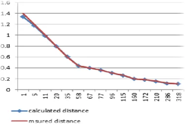
Figure 2. Comparison between the actual distance and the
calculated distance in MATLAB. The parameters used are: α 17.8,β 20.5, x 7.5 cm .
L: A variable that indicates the actual length of the image at a distance d. It can be calculated from the Equation (5).
2 tan
l d (5)
In these equations, l, represents the actual distance between the laser and the left boundary of the image at a distance d, in fact, the same number that pops out of the image processing. Also, in this model, Equations (6) and (7) should also be considered:
(6)
0 p 1 (7)
Finally, the value of X represents the distance between the center of the laser and the camera. The results based on the mentioned parameters are presented in Figure 2. The results are presented in Figure 2 along with the corresponding parameters. The parameters α and β should be set based on certain experimental setup. In this work, these parameters were achieved as α 17.8,β 20.5 . Using these parameters, the values of
dA and dB were obtained as dB1.4 m and 10.7
dA cm. The value of x is achieved by measuring the distance between the camera and the laser. Α is also obtained by experimental simulation in MATLAB and β is presented to limit the maximum calculated distance.
In Figure 2, the x-axis is the number of pixels that the laser beam is located in and the y axis indicates the distance to the desired object for each pixel of the image.
2. 2. FPGA-Based Implementation
2. 2. 1. The Advantages of an FPGA-Based Implementation Several kinds of computer hardware platforms can be considered to implement the processing of optical signals imaging systems; The common choice for implementation as a single processor system is a digital signal processor (DSP), or an application-specific integrated circuit (ASIC). The advantages of microprocessors such as being inexpensive, easily programmable and being off-the-shelf devices are satisfactory. In contrast, an ASIC is used for a specific expensive design which is inflexible and non-programmable [19].
With recent advancements in technology, FPGAs have become a perfect choice to implement a variety of computational systems. In fact, FPGAs are new interface between the microcontrollers and ASIC in terms of computational performance and cost requirements. Such as microcontrollers, FPGAs are inexpensive, off-the-shelf devices, and easily reprogrammable for new applications. Also, they have provided a high degree of control over the reference computer hardware as well as ASIC. As a result, it allows the system designer to implement predetermined hardware architecture with respect to computational volume of the program in hand [19].
In the past few years, made or proposed systems for a variety of applications dominated by mathematical calculations, including crosscorrelator for radio astronomy [20], a beam sonar [21], a two-dimensional convolvers [22, 23], fast Fourier transform [24] etc. prove that the FPGA-based implementations are typically at least one rank faster than CPU-based implementations without incurring the high cost of construction and development requirements for ASICs.
converted to white, otherwise to black. Then, the white pixels density is compared with each other and between them (if any) some range is reported as the laser light which has the same density and size of laser beam (a few pixels located next to each other in a circle form) [16].
3. RESULTS AND DISCUSSION
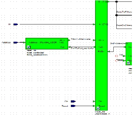
3. 1. Implementation of the Proposed Algorithm First, the image data are stored in external memories of the lab board, and then sent to the FPGA chip. Figure 3 shows RTL viewer of the interior architecture design using embedded development kit (EDK) tools from Xilinx Inc. In the following, the design of image processing blocks will be discussed.
It is assumed that the color information per pixel divided into three packages of 8-bit numbers which are the RGB components of the pixels. Therefore, the color information of the image from left to right is swept to three 8-bit numbers which are RED, GREEN and BLUE, respectively and saved in the 8-bit registers of external memory available on the Lab Board.
Now, the whole design process is presented by explaining the function of each module. The function of
First_controler module is to cut the color data from the place where the laser light is and to import them to the internal memory of the FPGA. It should be noted that, with respect to the laser and camera mounted to a fixed position towards each other, the laser light is relocated only horizontally by changing the distance between the object and the camera, and not vertically. To be sure, the image is vertically cut from the location of the laser light to 5 pixels and saved in the internal memory. Because of the isolated image size of 5 x 320, the internal memory should be with the depth of 48008-bit registers.
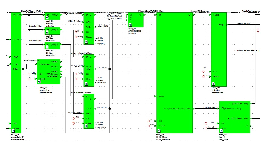
With the decree issued by the Controller module, the color data is passed through three filters simultaneously by the Memdata module which has the isolated image data. These filters are responsible for detecting the red color of the laser spot.
By passing through these filters, the 8-bit data are converted to zero and one, thus if the color was diagnosed one and zero otherwise. The First_controller
and Memdata modules are shown in Figure 4.
With the decree issued by the Controller module, three small memory r_mem, g_mem, b_mem save the information of filtered colors associated with them into their registers. These memories are shown in Figure 5.
Figure 3. RTL viewer blocks (total) of distance measurement algorithm in EDK tools.
Figure 5. Schematic of RGB_Mem blocks.
When all three filtered characteristics of each pixel is prepared, they will be AND together immediately. With the decree issued by the Controller module, the output data will be saved into a single bit memory, rgb_mem, with the depth of 1600.Therefore, the filtered image is stored in this memory. The tasks of the Controller module are to read the data correctly from the outside, to filter the color information appropriately and to import them into rgb_mem without any data loss. The
rgb_mem memory block has two outputs. With each clock, the output O sends the data of filtered color to the main output. The output L1 send the number of register which its data is sent out. The task of the detector module is to identify the rising edge of the output O of the rgb_mem module. In other words, detecting the red light during the scanning of each row, the detector
module would set the edge signal to one on its output. This signal sends the command of data reception to the average module.
The output of rgb_mem module, l1, which establishes the number of image pixels, is sent to a divider module called Div1 as its input. One of the output of Div1 is the residue of dividing l1 by 320 (image length), named L, which is the number of pixels from the left edge of image to the edges of circle of the red light. What we need is to calculate the number of pixels from the edge of image to the center of the red light circle. Thus, using the edge signal as mentioned before, estimated values of real L are saved in the
average module and the mean value is calculated. The schematic of average module is shown in Figure 6.
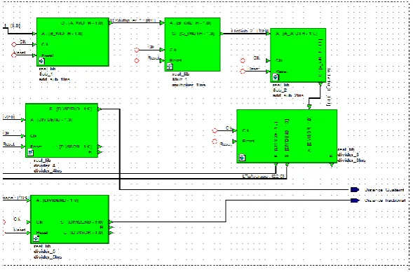
The other output of Div1 module, the integer part of the division, is a number between -1 and 5 and is sent to concatenation module. This module separates the least significant bit of the number and sends it to another
detector which produces the signals for indicating the passage of one row to another. The output of average module is sent to sub1, sub2, mult1 and mult2 to perform arithmetic operations needed for estimation of distance between the object and camera.
The output signals from these modules give us an integer and floating point value per row which is the estimation value of distance. For more accuracy, the values of each row are stored in the average fractional
and average quateint modules and their mean value is calculated to present the more accurate value of distance
to the object. The schematic of distance estimation blocks is shown in Figure 7.
3. 2. The Performance of the Implemented System
The numeric results of the implemented system using Xilinx EDK tools is shown in Figure 8. As can be seen, the period of system clock has been simulated considering delay of the Elements, gates and registers. It is done by adding a User Constraint to the project. In this work, first a default value is given to the system as a clock period. Then, according to the architecture and hardware of design, the software determines that whether or not it can make the relevant period. Then it provides the result as Figure 8 where it has been determined how much is the lowest clock period that can be applied to the system according to the design.
Also, it declares the difference with the default value, which can be positive or negative. This work was also carried out for the output delay.
As shown in Figure 8, a minimum clock period that can be applied to the system is19.57ns and differs from the default value, 0.43 ns respectively. The output delay is 4.86 ns, which is appropriate. With these explanations, the system can easily be fed with a 50 MHz clock that is appropriate for our work.
Figure 7. Schematic of distance estimation blocks in EDK tools.
In Figure 9, the data of one frame of image is given to the scheme for simulation and corresponding simulation is done in Modelsim software. The output has two parts including integer part and the decimal part which were obtained from distance measured from the input image. As seen in the figure, the run-time of one frame of the image is approximately 100 microseconds. This performance is useful for processing images at a rate of 30 frames per second and the response time of the system is satisfactory even without using the maximum processing power of FPGA.
As seen in the Figures 10, with the fact that the center for laser and camera lens are in the same direction, the location of the laser light in the vertical direction of image has been estimated. Then, this section has been cut off from main picture, so, less
pixels of image will be sent to processing blocks. Moreover, random objects that are the same color as laser may be separated from the image. Also, for more accuracy of detecting laser light in the picture and to unit it as a standalone object, a series of filtering blocks have been used even to fill the cavity inside the object. The result is shown on Figure 11.
Finally, the performance of the proposed algorithm is compared with other methods in different literatures. The result of this comparison is presented in Table 1. As can be seen, the proposed algorithm has better distance measuring performance and accuracy versus other methods from different literatures. It should be considered that some of these methods have also acceptable distance measuring performance such as [9].
Figure 9. Processing simulation of one frame of image in Modelsim software.
Figure 10. Laser light where there is a possibility of error.
Figure 11. Result of Image processing blocks based on a color
pixel even in a red area.
TABLE 1. Comparison of distance measuring performance of
various methods from different literature
References Accuracy rate of distance measurement Up to Method or device used
[3] 94% Ultrasound device
[4] 96% Rotating mirror
[5] 94.11% eye-distance
[6] 97.0% IR & Ultrasonic sensor
[7] 97.3% Modified Camera
[8] 97.1% Ultrasound sensor
[9] 99.48% cross correlation + ultrasound
Proposed
methods 99.62%
Laser transmitter & CMOS camera
3. 3. The Performance of Camera and Laser This device has good performance for indoor environments, factories, workshops, etc. which are benefitting from favorable light.
system may inform the wrong distance or laser detection, which, as stated above, causes damage to the system used. In the case of the environment with the light more than usual, it is difficult for the camera to detect the laser light and it may reduce the maximum distance of obstacle detection which also means reducing the performance of the system.
4. CONCLUSION
In this paper, an accurate and fast scheme for real – time distance measurement based on FPGA was presented. First, an algorithm was presented to measure the distance from the object back to the camera. Then the algorithm was implemented using Verilog language and corresponding simulation was done in Modelsim software.
The output has two parts including integer part and the decimal part which were obtained from distance measured from the input image. Using spartan3 / xc3s400 Xilinx family, the design was implemented relatively simple, fast and inexpensive. As shown, the run-time of one frame of the image is approximately 100 microseconds. This performance is useful for real time image processing at a rate of more than 30 frames per second.
5. ACKNOWLEDGMENTS
The authors would like to thank Prof. R. A. Naghizadeh for his valuable comments and suggestions which helped enhance the quality of the paper.
6. REFERENCES
1. Wu, L.H., Xu, W.H. and Li, Y.P., "Detection parameters design for compound survey seafloor targets by multibeam sonar",
Indonesian Journal of Electrical Engineering and Computer
Science, Vol. 11, No. 8, (2013), 4306-4316.
2. Fei-yu, L., "Research on obstacle recognition for uuv based on multi-beam forward looking sonar", Indonesian Journal of
Electrical Engineering and Computer Science, Vol. 11, No. 5,
(2013), 2657-2662.
3. Chang, C.C., Lin, C.C., Wang, J.H., Der Jeng, M. and Tseng, S.H., "The study of ultrasonic distance measurement device for a teleoperated robotic manipulator system", IEEE Conference and Exhibition,. Vol. 2, (2001), 1054-1057.
4. Kim, H., Lin, C., Song, J. and Chae, H., "Distance measurement using a single camera with a rotating mirror", International
Journal Of Control Automation And Systems, Vol. 3, No. 4,
(2005), 542-550.
5. Rahman, K.A., Hossain, M.S., Bhuiyan, M.A.-A., Zhang, T., Hasanuzzaman, M. and Ueno, H., "Person to camera distance measurement based on eye-distance", in Multimedia and Ubiquitous Engineering. MUE'09. Third International Conference on, IEEE. (2009), 137-141.
6. Mohammad, T., "Using ultrasonic and infrared sensors for distance measurement", World Academy of Science,
Engineering and Technology, Vol. 51, (2009), 293-299.
7. Xiaoming, L., Tian, Q., Wanchun, C. and Xingliang, Y., "Real-time distance measurement using a modified camera", in Sensors Applications Symposium (SAS), IEEE. (2010), 54-58.
8. Shrivastava, A., Verma, A. and Singh, S., "Distance measurement of an object or obstacleby ultrasound sensors using P89C51RD2", International Journal of Computer Theory and
Engineering, Vol. 2, No. 1, (2010), 64.
9. Wang, J., Yuan, D. and Cai, P., "Range resolution of ultrasonic distance measurement using single bit cross correlation for robots", in Information and Automation (ICIA), International Conference, IEEE. (2010), 917-923.
10. Mekhilef, S. and Rahim, N., "Generation of three-phase pwm inverter using xilinx fpga and its application for utility connected pv system (research note)", International Journal of
Engineering-Transactions B: Applications, Vol. 17, No. 3,
(2004), 273.
11. Yuan, M., "Field programmable gate array implementation of active control laws for multi-mode vibration damping",
International Journal of Engineering-Transactions B:
Applications, Vol. 29, No. 2, (2016), 229.
12. Mandal, A. and Mishra, R., "Design and implementation of digital demodulator for frequency modulated cw radar",
International Journal of Engineering Transactions A: Basics,
Vol. 27, No. 10, (2014), 1581-1590.
13. Romero-Troncoso, R.J., Saucedo-Gallaga, R., Cabal-Yepez, E., Garcia-Perez, A., Osornio-Rios, R.A., Alvarez-Salas, R., Miranda-Vidales, H. and Huber, N., "FPGA-based online detection of multiple combined faults in induction motors through information entropy and fuzzy inference", IEEE
Transactions on Industrial Electronics, Vol. 58, No. 11,
(2011), 5263-5270.
14. Ashourian, M., Daneshmandpoura, N., Tehrania, O.S. and Moallemb, P., "Real time implementation of a license plate location recognition system based on adaptive morphology",
International Journal of Engineering, Vol. 26, No. 11, (2013),
1347-1356.
15. Akbarpour, H., Karimi, G. and Sadeghzadeh, A., "Discrete multi objective particle swarm optimization algorithm for fpga placement (research note)", International Journal of
Engineering-Transactions C: Aspects, Vol. 28, No. 3, (2014),
410-417.
16. Poon, T.-C. and Banerjee, P.P., "Contemporary optical image processing with matlab, Elsevier, (2001).
17. Gonzalez, W. and Woods, R.E., "Eddins, digital image processing using matlab", Third New Jersey: Prentice Hall, (2004).
18. Yuan, D. and Manduchi, R., "Dynamic environment exploration using a virtual white cane", in Computer Society Conference on Computer Vision and Pattern Recognition (CVPR'05), IEEE. (2005), 243-249.
19. Carletta, J., Giakos, G., Patnekar, N., Fraiwan, L. and Krach, F., "Design of a field programmable gate array-based platform for real-time de-noising of optical imaging signals using wavelet transforms", Measurement, Vol. 36, No. 3, (2004), 289-296. 20. Von Herzen, B., "Signal processing at 250 mhz using
high-performance FPGA'S", in Proceedings of the ACM fifth international symposium on Field-programmable gate arrays, ACM., (1997), 62-68.
21. Graham, P. and Nelson, B., "Fpga-based sonar processing", in Proceedings of the ACM/SIGDA sixth international symposium on Field programmable gate arrays, ACM., (1998), 201-208. 22. Bosi, B., Bois, G. and Savaria, Y., "Reconfigurable pipelined
Transactions on Very Large Scale Integration (VLSI) Systems, Vol. 7, No. 3, (1999), 299-308.
23. Singh, S., "Accelerating adobe photoshop with reconfigurable logic", in IEEE Symposium on FPGA Custom Computing Machines, Citeseer., (1998).
24. Shaditalab, M., Bois, G. and Sawan, M., "Self-sorting radix-2 FFT on FPGAs using parallel pipelined distributed arithmetic blocks", in FPGAs for Custom Computing Machines,. Proceedings. Symposium on, IEEE., (1998), 337-338.
Field Programmable Gate Array–based Implementation of an Improved
Algorithm for Objects Distance Measurement
TECHNICAL NOTE
H. Zivarian, M. Soleimani, M. H. DoostMohammadi
Department of Electrical Engineering, Hamedan University of Technology, Hamedan, Iran
P A P E R I N F O
Paper history: Received 02 October 2016
Received in revised form 20 November 2016 Accepted 28 December 2016
Keywords: Distance measurement image processing
field programmable gate array implementation
machine vision
ديكچ ه
هلصاف ماگنهب متیروگلا یزاس هدایپ یارب ،راک نیا رد تخس رتسب کی ،یجنس
رب ینتبم هفرص هب نورقم یرازفا
FPGA
هئارا
مرن زا هدافتسا اب یداهنشیپ متیروگلا .تسا هدش تکرش هعسوت یاهرازفا
Xilinx
پیچ یور رب
spartan3 / xc3s400
هدایپ
پیچ زا یکی هدافتسا دروم پیچ .دش یزاس تکرش ناتراپسا هداوناخ زا نازرا و لومعم یاه
Xilinx
یم .دشاب ریخأت
تخس زا رتمک هدش هئارا رازفا 100
رد هیناثورکیم 5000
سناکرف اب تعاس لکیس 50
یم زترهاگم زا رتمک بتارم هب هک دشاب
شزادرپ نامز 82
یلیم هیناث مرن رد نآ یا رازفا
MATLAB
هیبش و یلمع جیاتن .تسا هب یزاس
یم ناشن حوضو هک دهد
تخس رب ینتبم یداهنشیپ رازفا
FPGA
هلصاف تیلباق ، یجنس
ماگنهب هدمآ تسدب ریواصت یم اراد ار نیبرود زا
.دشاب
یم ار رتسب نیا ،نیاربانب نیشام ییانیب هب هک یمتسیس ره رد ناوت
ماگنهب هبش ای ماگنهب .دومن هدافتسا ،دراد زاین