TECHNICAL NOTE
EFFECT OF DIRECT INJECTION DIESEL ENGINE CONVERT
TO SEQUENTIAL INJECTION CNG ENGINE IN INTAKE
PORT GAS FLOW PRESSURE PROFILE
S. Semin*, A.R. Ismail, R.A. Bakar and I. Ali
Automotive Excellent Center, Faculty of Mechanical Engineering University Malaysia Pahang, Locked Bag 12, 25000 Kuantan
Pahang, Malaysia
[email protected] - [email protected] - [email protected] - [email protected]
*Corresponding Author
(Received: February 28, 2008 – Accepted in Revised Form: May 9, 2008)
Abstract The one dimension computational model of a sequential injection engine, which runs on compressed natural gas (CNG) with spark ignition, is developed for this study, to simulate the performance of gas flow pressure profile, under various speed conditions. The computational model is used to simulate and study of the steady state and transient processes of the intake manifold. The sequential injection CNG engine model is developed using GT-Power software. The size of this model engine is developed from the real diesel engine data and was input into the software's' library. The simulation model engine runs with various speeds from 1000 up to 4000 rpm. The simulation results of the performance with gas flow pressure, in the intake manifold are collected from two data sets; the GT-Post post processing plots for pressure performance versus crank angle, and post processing cases RLT for pressure performance versus engine speed. The simulation results of the intake manifold and the performance of the gas flow pressure profile, with various engine speed, for the CNG sequential injection engine are shown by characters. The Pressure profile of the engine and the numerical accuracy of the model is verified and validated by comparing the average total of the intake manifold pressure, with the measured intake manifold pressure, of a CNG sequential injection engine. The simulation results show that, the conversion of diesel engine to a CNG sequential injection engine with spark ignition will increase the pressure performance in the intake manifold of the engine.
Keywords Diesel Engine, Intake Manifold, Pressure, Sequential Injection CNG Engine
ﻩﺪﻴﮑﭼ
ﻩﺪـﺷ ﻩﺩﺮﺸـﻓ ﯽﻌﻴﺒﻃ ﺯﺎﮔ ﯽﺒﻴﺗﺮﺗ ﺭﻮﺘﮐﮋﻧﺍ ﯼﺍ ﻪﻗﺮﺟ ﺭﻮﺗﻮﻣ ﯼﺪﻌﺑ ﮏﻳ ﯽﺿﺎﻳﺭ ﻝﺪﻣ (CNG)
ﻪﻴﺒـﺷ ﯼﺍﺮـﺑ
ﺪﺷ ﻩﺩﺍﺩ ﻂﺴﺑ ﻖﻴﻘﺤﺗ ﻦﻳﺍ ﺭﺩ ﺭﻮﺗﻮﻣ ﺖﻋﺮﺳ ﻒﻠﺘﺨﻣ ﻂﻳﺍﺮﺷ ﺭﺩ ﺯﺎﮔ ﻥﺎﻳﺮﺟ ﺭﺎﺸﻓ ﻞﻴﻓﻭﺮﭘ ﯼﺯﺎﺳ .
ﯽـﺿﺎﻳﺭ ﻝﺪـﻣ ﺭﺩ
ﯽﻣ ﻪﺘﻓﺮﮔ ﺮﻈﻧ ﺭﺩ ﯼﺩﻭﺭﻭ ﺪﻠﻔﻴﻧﺎﻣ ﯼﺍﺭﺬﮔ ﯼﺯﺎﺳ ﻪﻴﺒﺷ ﻪﺳﻭﺮﭘ ﻭ ﺖﺧﺍﻮﻨﮑﻳ ﺖﻟﺎﺣ ﺩﻮﺷ
. ﻣ ﯽـﺒﻴﺗﺮﺗ ﺭﻮﺘﮐﮋﻧﺍ ﺭﻮﺗﻮﻣ ﻝﺪ
CNG ﺭﺍﺰﻓﺍ ﻡﺮﻧ ﮏﻤﮐ ﻪﺑ GT-Power
ﺪﺷ ﻩﺩﺍﺩ ﻂﺴﺑ .
ﯽـﻌﻗﺍﻭ ﻝﺰﻳﺩ ﺭﻮﺗﻮﻣ ﻪﺑ ﻁﻮﺑﺮﻣ ﺕﺎﻋﻼﻃﺍ ﺯﺍ ﺭﻮﺗﻮﻣ ﻝﺪﻣ ﻩﺯﺍﺪﻧﺍ
ﺪﺷ ﻩﺩﺍﺩ ﺭﺍﺰﻓﺍ ﻡﺮﻧ ﻪﺑ ﻭ ﺝﺍﺮﺨﺘﺳﺍ .
ﺯﺍ ﻒﻠﺘﺨﻣ ﯼﺎﻫ ﺖﻋﺮﺳ ﺭﺩ ﺭﻮﺗﻮﻣ ﻝﺪﻣ ﯼﺯﺎﺳ ﻪﻴﺒﺷ ١٠٠٠
ـﺗ ﺎ rpm ٤٠٠٠ ﻡﺎـﺠﻧﺍ
ﺪﺷ . ﻧ
ـﮔ ﻥﺎﻳﺮﺟ ﺭﺎﺸﻓ ﺩﺮﮑﻠﻤﻋ ﯼﺯﺎﺳ ﻪﻴﺒﺷ ﺞﻳﺎﺘ ﺞﻳﺎـﺘﻧ ﺵﺯﺍﺩﺮـﭘ ﺯﺍ ﯼﺩﻭﺭﻭ ﺪـﻠﻔﻴﻧﺎﻣ ﺭﺩ ﺯﺎ
GT-Post ﻦﻴـﻴﻌﺗ ﯼﺍﺮـﺑ
ﺪﺷ ﻞﺻﺎﺣ ﺭﻮﺗﻮﻣ ﺖﻋﺮﺳ ﺐﺴﺣ ﺮﺑ ﺭﺎﺸﻓ ﺩﺮﮑﻠﻤﻋ ﻦﻴﻨﭽﻤﻫ ﻭ ﮓﻨﻟ ﻞﻴﻣ ﻪﻳﻭﺍﺯ ﺐﺴﺣﺮﺑ ﺭﺎﺸﻓ ﺩﺮﮑﻠﻤﻋ .
ﻪﻴﺒﺷ ﺞﻳﺎﺘﻧ
ﯽﺒﻴﺗﺮﺗ ﺭﻮﺘﮐﮋﻧﺍ ﺭﻮﺗﻮﻣ ﯼﺩﻭﺭﻭ ﺪﻠﻔﻴﻧﺎﻣ ﯼﺯﺎﺳ CNG
ﯼﺩﻭﺭﻭ ﺪﻠﻔﻴﻧﺎﻣ ﺯﺎﮔ ﻥﺎﻳﺮﺟ ﺭﺎﺸﻓ ﻞﻴﻓﻭﺮﭘ ﺩﺮﮑﻠﻤﻋ ﯼﺎﻫ ﯽﮔﮋﻳﻭ ،
ﺍﺮﻴﻴﻐﺗ ﺭﺩ ﺍﺭ ﯽﻣ ﻥﺎﺸﻧ ﺭﻮﺗﻮﻣ ﺖﻋﺮﺳ ﺕ
ﺪﻫﺩ . ﻭ ﯼﺩﻭﺭﻭ ﺪـﻠﻔﻴﻧﺎﻣ ﻞـﮐ ﺭﺎﺸـﻓ ﻦﻴﮕﻧﺎـﻴﻣ ﻪﺴـﻳﺎﻘﻣ ﺎـﺑ ﻝﺪﻣ ﯼﺩﺪﻋ ﺖﻗﺩ
ﯽﺒﻴﺗﺮﺗ ﺭﻮﺘﮐﮋﻧﺍ ﺭﻮﺗﻮﻣ ﺭﺩ ﯼﺩﻭﺭﻭ ﺪﻠﻔﻴﻧﺎﻣ ﺭﺎﺸﻓ ﻩﺪﺷ ﯼﺮﻴﮔ ﻩﺯﺍﺪﻧﺍ ﺮﻳﺩﺎﻘﻣ CNG
ﺭﺍﺮﻗ ﺪﻴﻳﺎﺗ ﺩﺭﻮﻣ ﺖﻓﺮﮔ
. ﻪﻴﺒـﺷ ﺞﻳﺎﺘﻧ
ﻥﺎﺸﻧ ﯼﺯﺎﺳ ﺩﺍﺩ
ﯽﺒﻴﺗﺮﺗ ﺭﻮﺘﮐﮋﻧﺍ ﯼﺍ ﻪﻗﺮﺟ ﺭﻮﺗﻮﻣ ﻪﺑ ﻝﺰﻳﺩ ﺭﻮﺗﻮﻣ ﻞﻳﺪﺒﺗ ﻪﮐ CNG
ﻮﺳ ﺭﺎﺸﻓ ﺩﺮﮑﻠﻤﻋ ﺶﻳﺍﺰﻓﺍ ﺚﻋﺎﺑ ﺯ
ﯽﻣ ﺭﻮﺗﻮﻣ ﯼﺩﻭﺭﻭ ﺪﻠﻔﻴﻧﺎﻣ ﺭﺩ ﺩﻮﺷ
.
1. INTRODUCTION
Environment protection and economical fuel
industries and transportations [1-5]. There is an increasing need to research and employ new technology to design a new engine or its components that can use alternative fuels other than gasoline and diesel, which will in turn be more environmental friendly, high in power and efficient in fuel consumption.
To link the performance of the internal combustion engine theory with the computer modeling of the engine thermodynamics, for engine simulations is a great challenge, since the latter makes the most complete use of the former and the use of this model is becoming widespread. Engine modeling is a very popular subject, in part because of the ranges of possible engine configurations, and the variety of alternative analytical techniques which can be applied, or sub-models in overall engine sub-models [1]. Engine modeling is a fruitful research area, and as a result many universities have produced their own engine thermodynamic models, of varying degrees of complexity, scope and easy to use. There are also a number of fairly comprehensive models developed by engineers, which have a wider, more general usage with refined inputs and outputs to facilitate their usage. Most of these models originated from university-developed models [6]. They include WAVE from the U.S.A., PROMO from Germany and TRANSEG/ICENG/ MERLIN from the U.K. [1]. A new code covering completes engine systems have emerged recently, that is the GT-Suite [1].
The steady state and transient simulation of gas flow in the intake manifold of sequential injection compressed natural gas (CNG) engine uses GT-Power software. This research focuses on single cylinder four strokes sequential injection dedicated CNG engine with spark ignition. The aim is to give an insight into the engines' intake manifold gas flow thermodynamics performance, by using the GT-Power simulation model could find how the engine model developed and the components interacts.
The sequential injection CNG engine has an injector for each cylinder, so these injectors can be placed in close proximity to the cylinder's intake port. It also enables fuel to be delivered precisely as required to each individual cylinder (called sequential) and enables more sophisticated technologies such as skip-firing to be used.
Skip-firing is when some cylinders operate and others skip. This enables even more efficient use of the fuel at low loads, further lowering fuel consumption and unburned hydrocarbon emissions [7-12]. The gas fuel is usually injected at high velocity as one or more jets, through small orifices or nozzles at the injector tip, via intake port into the combustion chamber. The gas fuel mixes at high temperature and high air pressure, in cylinder. The air is supplied from intake port of the engine. Since the temperature and pressure of the air and gas are near the ignition point, thus the spark ignites of portions of already-mixed gas fuel and after air input a delay period of few crank angle degree occurs. The cylinder pressure increases as the combustion of gas-air mixture occurs [1,12,13].
The major design problem in the combustion chamber of a spark ignition CNG engine is, achieving sufficiently rapid mixing between the injected gas fuel and the air from intake port of the cylinder, to complete combustion in the appropriate crank angle interval close to top-center [8,12,14-17]. Horsepower output of an engine can be dramatically improved with a good design and manufacturing of the intake port [18].
To determine the condition of the gas flow right through the engine is the essence of modeling at small time interval. Gas flow condition through the engine basically means pressures, temperatures, gas composition and mass or energy flow. The core of any model is the energy equation for each control volume in the engine [1]. The first essential item in a model engines' performance, is the energy for a control volume, which is derived from the first law of thermodynamics and the perfect gas law. The first law states that, the rate of change of internal energy of the volume from connected gas flow, minus any net heat transfer out through the volume walls and also minus any work done by the control volume gas, against its surroundings as shown in Equation 1.
( )
⎟⎠ ⎞ ⎜ ⎝ ⎛ − − ∑ =
dt dV P dt dQ l himi dt
uM d
& (1)
flow rate mi and negative for outflow. Net heat transfer out of the control volume is dQ/dt, M is the mass of gas in the control volume at pressure P and this gas carries out a net work of its surroundings PdV/dt, where dV/dt is the control volume’s current rate of change of volume and zero for manifold control volume and not for cylinder control volume.
To determine the flow through a pipe and its constriction the orifice equation is needed, in an internal combustion engine [1]. The stagnation or total temperature Tt at any point in a flow is given by Equation 2,
2 2 v T p c t T p
c = + (2)
Where, Tt is the temperature that the gas flows at the velocity v with static temperature T would reach if it were brought to rest adiabatically, the equation is simply an energy balance, cpT being a measure of the static energy, v2/2 the kinetic energy and cpTt the total energy or enthalpy. And to determine the mach number Ma is using equation (3), where c is velocity of sound, γ is equal with cp/cv and cp-cv = R.
(
γRT)
v c v a
M = = (3)
Relationship of total to static temperature is obtained using Equation 4 and 5. Then the total static pressure equation is shown in Equation 6. The total static pressure will increase if the total temperature in any point Tt and gas flow velocity v is increase. p 2c 2 a γRTM 1 p 2c 2 v 1 T t T + = +
= (4)
(
)
2 2 a M 1 γ 1 T t T − += (5)
1 γ γ 2 a M 2 1 γ 1 1 γ γ Tt T Pt P − ⎥ ⎦ ⎤ ⎢ ⎣ ⎡ ⎟ ⎠ ⎞ ⎜ ⎝ ⎛ − + = − ⎟ ⎟ ⎠ ⎞ ⎜ ⎜ ⎝ ⎛
= (6)
2. MATERIALS AND METHODS
The computational modeling of four stroke sequential injection CNG engine with spark ignition is developed using GT-POWER software, based on real engine selected data. According to [6,7,15,19,20-24], the specification of the engines and intake parameter of diesel engine and CNG engine are shown in Table 1. In the GT-POWER engine model development, a typical intake manifold is modeled using Inport, while engine is modeled using EngCylinder and EngineCrankTrain, the component objects are the Valve*Conn and EngCylConn connection objects [25].
The diesel engine converted or designed to run on dedicated natural gas engines are optimized for the natural gas fuel. They can be derived from spark ignition engines or may be designed for this purpose. Since Original Equipment Manufacturer (OEM) engines are more readily available, the practice of converting diesel engines to spark ignition CNG engine will continue, which involves the replacement of diesel fuelling equipment by a gas sequential injection system with the addition of an ignition system and spark plugs.
TABLE 1. Specification the Engine
.
Engine and Intake Parameter Diesel Engine CNG Engine
Bore (mm) 86.0 86.0
Stroke (mm) 70.0 70.0
Displacement (cc) 407.0 407.0
Compression Ratio 20.28 14.5
Intake Valve Close (CA) 496 496
Exhaust Valve Open (CA) 191 191
Intake Valve Open (CA) 361 361
Exhaust Valve Close (CA) 325 325
Ignition System Compression Spark
Fuel System Direct Injection Port Injection
Fuel Diesel Natural Gas
Intake Port Diameter in (mm) 40.69 40.69
Intake Port Diameter out (mm) 32.78 32.78
Intake Port Length (mm) 55.2 55.2
Discreatization Length (mm) 34.4 34.4
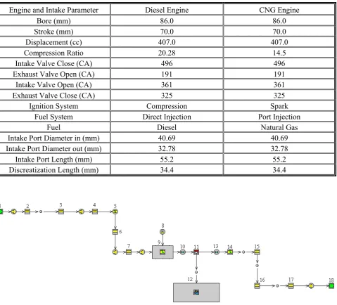
Figure 1. Sequential injection CNG engine model using GT-POWER.
1. Is intake environment, 2. Is intake pipe 1, 3. Is air cleaner, 4. Is intake pipe 2, 5. Is throttle, 6. Is intake pipe 3, 7. Is intake runner, , 8. Is fuel injector, 9. Is intake port, 10. Is intake valve, 11. Is engine cylinder, 12. Is engine crank train, 13. Is exhaust valve,
14. Is exhaust port, 15. Is exhaust runner, 16. Is muffler, 17. Is exhaust pipe and 18. Is exhaust environment. Components 1 to 10 are intake system, components 11 to 12 are engine,
and components 13 to 18 are exhaust system.
used to define the basic geometry and characteristics of engine. These objects further refer to several reference objects, for more detailed modeling information on such attributes as gas flow temperature. Intake manifold is connected to the
engine cylinder with the Valve*Conn and engine cylinder must be connected to the engine with the EngCylConn part, which is made of predefined object, available in the template library.
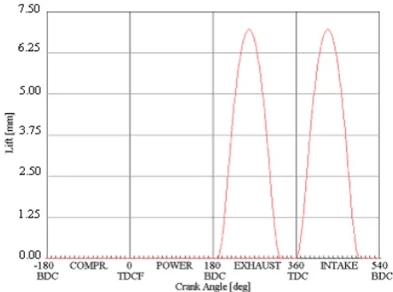
Figure 2. Intake and exhaust valve lift of CNG engine and diesel engine.
defined attributes, the global cylinder number for cylinder is assigned by the port number where the EngCylConn connection is attached to the engine. Cylinder are connected to intake and exhaust ports with Valve*Conn connections. Many Valve*Conn connection templates are available to define different types of valve, port and their characteristics.
Solver of GT-POWER determines the performance of an engine model simulation, based on engine speed mode in the EngineCrankTrain object [25]. Speed mode is the most commonly used mode of engine simulation, especially for steady states cases [13,25]. This research imposes the engine speed as either constant or by a dependency reference object. This method typically provides steady-state results very quickly because the speed of the engine is imposed from the beginning of the simulation, thus eliminating the relatively long period of time that a loaded engine requires for the crankshaft speed to reach steady-state.
3. RESULTS AND DISCUSSION
The investigation of the four stroke sequential injection CNG engine with spark ignition system is running in 4 different cases of engine speed for GT-Post post processing plot and 7 different cases of engine speeds for GT-Post post processing casesRLT. For post processing plot, case 1 is engine running at 1000 rpm, case 2 is engine running at 2000 rpm, case 3 is engine running at 3000 rpm and case 4 is engine running at 4000 rpm. GT-Post post processing plot result is the intake manifold static pressure versus crank angle degree based on engine speed. GT-Post post processing casesRLT results are the intake manifold pressure, versus engine speed based on any speed, engine speeds varies from 1000 rpm-4000 rpm.
Both sequential injection CNG engine spark ignition and diesel engine are operated in the same valve timing and combustion start. So, the valve timing profile of both engines is the same. The valve timings' open and close angles data are shown in Table 1 and the valve lift profile of both engines are shown in Figure 2. In the diesel
combustion, the fuel injection start is, at-22.0 crank angle degree and the combustion start is at-21.1 crank angle degree. In the sequential injection CNG engine, the combustion starts at-21.1 of crank angle degree, which is the same as diesel engine. Gas fuel is injected during the intake strokes and would follow the intake valve lift profile, where the gas fuel injection process started at 30.4 BTDC, and the injection duration is, at 7.4 crank angle degrees.
The static pressure characteristics in the intake manifold pressure profile of four stroke sequential injection CNG engine, and simulations results from GT-Post post processing plots compared with direct injection diesel engine are shown in Figures 3 and Figure 10.
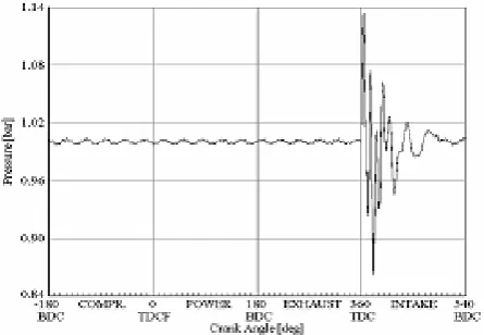
Figure 3. Diesel engine intake port static pressure in 1000
rpm.
Figure 4. Diesel engine intake port static pressure in 2000
rpm.
Figure 5. Diesel engine intake port static pressure in 3000
rpm.
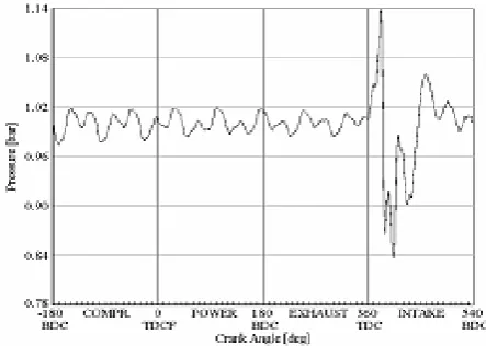
the diesel engines' intake manifold static pressure, versus crank angle profile at 4000 rpm engine speed. Figure 7 shows the sequential injection CNG engines' intake manifold static pressure versus crank angle profile at 1000 rpm. Figure 8 shows the sequential injection CNG engine intake manifold static pressure versus crank angle profile at 2000 rpm. Figure 9 shows the CNG engine intake manifold static pressure versus crank angle in 3000 rpm and Figure 10 shows the sequential injection CNG engine intake manifold static pressure versus crank angle profile at 4000 rpm engine speed. Figures 3 and 6 show the intake manifold static pressure profile versus crank angle profile at 1000-4000 rpm of the diesel and CNG engines. In this speed for both of the engine, nominal static pressure in the intake manifold is the most extreme, when compression stroke is compared with the power and exhaust strokes. The intake stroke, started from static pressure when the intake valve started to open. The intake valve opened and the static pressure extremely increased because during the stroke, the cylinder needs to suck the air in, to mix with the fuel, for the engine combustion to produce power. When the intake valve is closed, the static pressure is very low, because in this process the gas flow in the intake manifold is crass with back static pressure from closed intake valve. Then the static pressure lowers in compression stroke, when power and exhaust stroke are the lowest.
The highest static pressure in the intake port, during an intake stroke of a diesel engine, is 1.335 bars, observed at 4000 rpm, as shown in Figure 6. This is because of the excellent combustion at the said speed, needing most air for the process. The minimum static pressure is 0.624 bar, also observed at 4000 rpm as a shown in Figure 6 .In this investigation the combustion and the intake valve lift, closes quickly. Thus the air flow backs up and the static pressure from closing of intake valve is higher than the other engine speed.
Figure 6. Diesel engine intake port static pressure in 4000
rpm.
Figure 7. CNG engine intake port static pressure in 1000 rpm.
Figure 8. CNG engine intake port static pressure in 2000 rpm.
Figure 9. CNG engine intake port static pressure in 3000 rpm.
Figure 10. CNG engine intake port static pressure in 4000 rpm.
valve lift and close very quickly so that the air flow backs up static pressure from the intake valve and closes faster than other lower engine speed.
0.9945 0.9955 0.9965 0.9975 0.9985 0.9995 1.0005
1000 1500 2000 2500 3000 3500 4000
Engine Speed (rpm)
A ve rag e P res su re In le t (B ar)
. CNG EngineDiesel Engine
Figure 11. Average pressure inlet at intake manifold.
0.9933 0.9954 0.9975 0.9996 1.0017
1000 1500 2000 2500 3000 3500 4000
Engine Speed (rpm)
A verag e P res su re O ut le t (B ar) CNG Engine Diesel Engine
Figure 12. Average pressure outlet at intake manifold.
1.0 1.1 1.2 1.3 1.4 1.5 1.6
1000 1500 2000 2500 3000 3500 4000
Engine Speed (rpm)
Ma xi m um P res su re In le t (B ar) CNG Engine Diesel Engine
Figure 13. Maximum pressure inlet at intake manifold.
1.0 1.1 1.2 1.3 1.4 1.5 1.6
1000 1500 2000 2500 3000 3500 4000
Engine Speed (rpm)
M ax im um P res su re Ou tlet (B ar )
. CNG Engine
Diesel Engine
Figure 14. Maximum pressure outlet at intake manifold.
0.5555 0.6055 0.6555 0.7055 0.7555 0.8055 0.8555 0.9055 0.9555 1.0055
1000 1500 2000 2500 3000 3500 4000
Engine Speed (rpm)
M in imu m P re ss ur e In le t (B ar) CNG Engine Diesel Engine
Figure 15. Minimum pressure inlet at intake manifold.
0.5 0.6 0.7 0.8 0.9 1.0
1000 1500 2000 2500 3000 3500 4000
Engine Speed (rpm)
M in im um P re ss ur e Ou tle t (B ar) CNG Engine Diesel Engine
0.00 0.20 0.40 0.60 0.80 1.00 1.20
1000 1500 2000 2500 3000 3500 4000
Engine Speed (rpm)
Pres
su
re A
m
pl
it
ud
e
In
le
t (Bar
) CNG Engine
Diesel Engine
Figure 17. Pressure amplitude inlet at intake manifold.
0.10 0.30 0.50 0.70 0.90 1.10
1000 1500 2000 2500 3000 3500 4000
Engine Speed (rpm)
Pr
essur
e A
m
pl
itu
de
O
ut
le
t (
B
ar
) CNG Engine
Diesel Engine
Figure 18. Pressure amplitude outlet at intake manifold.
0.9985 0.9990 0.9995 1.0000 1.0005 1.0010 1.0015 1.0020
1000 1500 2000 2500 3000 3500 4000
Engine Speed (rpm)
A
ve
ra
ge
T
ota
l P
re
ssur
e
In
le
t (
B
ar
) CNG Engine
Diesel Engine
Figure 19. Average total pressure inlet at intake manifold.
and outlet pressure in the intake port at 1000-4000 rpm.
Figure 11 shows the average inlet pressure to the intake manifold from the intake runner, the highest is at 1000 rpm, for both CNG and diesel engines. The trend of the average inlet pressure in intake manifold both of CNG and diesel engines will decrease if the engine speed increases. The average inlet pressure at intake manifold of CNG engine is higher than diesel. The average outlet pressure from the intake manifold to the engine cylinder is shown in Figure 12. The lowest average outlet pressure is at 4000 rpm for diesel and 2500 rpm for CNG engines. Average outlet pressure at intake manifold of CNG engine is higher than diesel.
0.9990 0.9995 1.0000 1.0005 1.0010 1.0015
1000 1500 2000 2500 3000 3500 4000
Engine Speed (rpm)
A
ver
ag
e To
tal
P
res
su
re
Ou
tl
et
(B
ar
)
. CNG Engine
Diesel Engine
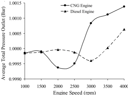
Figure 20. Average total pressure outlet at intake manifold.
0.9990 0.9995 1.0000 1.0005 1.0010 1.0015 1.0020
1000 1500 2000 2500 3000 3500 4000
Engine Speed (rpm)
Pr
es
su
re i
n In
ta
ke
M
an
ifo
ld
(B
ar) .
CNG Engine Model Diesel Engine CNG Engine Developed
Figure 21. Pressure of gas flow at intake manifold.
outlet pressure from intake manifold to the engine cylinder. Minimum pressure inlet/outlet of CNG engine is higher than diesel engine.
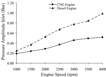
Figures 17 and 18 are show the inlet/outlet amplitude pressure at intake manifold. The highest nominal for maximum inlet/outlet amplitude are shown at 4000 rpm and the lowest at 1000 rpm. The gap of CNG and diesel engine inlet and outlet amplitude pressure are zero at 1000 rpm, thus increasing the engine speed will increase inlet and outlet amplitude pressure.
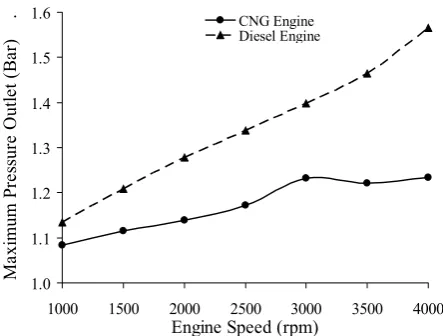
Average total pressure is minimum pressure added to maximum pressure and then divided by two. Average total pressure from the inlet process to intake port and outlet process from the intake manifold to the engine cylinder is shown in Figures 19 and 20. Figures 19 and 20 show that, the highest average inlet pressure to intake manifold is at 4000 rpm both for CNG and diesel engines. The lowest total average inlet pressure is at 3000 rpm for diesel engine and 2000 rpm for CNG engine. The total average inlet pressure at intake manifold of CNG engine is higher than diesel engine. The highest total average outlet pressure from intake manifold is at 4000 rpm for both CNG and diesel engine .The lowest total average outlet pressure from intake manifold is at 3000 rpm for diesel engine and 2000 rpm for CNG engine. The total average outlet pressure of CNG engine is higher than diesel.
The pressure of gas flow at the intake manifold is the mean average total pressure inlet and outlet. Figure 21 shows the pressure of gas flow at intake manifold of sequential injection CNG engine model, compared with diesel engine. The final result shows that the trend of CNG engine model with CNG engine developed is equal, and increasing engine speed will increase the gas flow at intake manifold. The minimum pressure of gas flow at the intake manifold is at 2000 rpm and after that, by increasing engine speed up to 4000 rpm will increase the pressure of gas flow at the intake manifold. The intake manifold gas flow pressure of CNG engine both, the model and the developed are higher than the diesel engine. It means that the sequential injector in the intake manifold will increase mass flow, thus the effect of increasing mass flow increases pressure. Theoretically, to increase the CNG engine is to increase the intake of gas flow and pressure.
4.CONCLUSSION
both for CNG and diesel engine. Both maximum and minimum inlet/outlet pressure in the intake manifold, for CNG engine is lower than diesel. The total average inlet and outlet pressure developed in the intake manifold of CNG engine model is higher than diesel engine, so the use of CNG fuel for engine will increase the intake pressure at the intake port of the engine. The model performance is higher than the other, because in model the ambient effect is zero, but in the real engine it will have nominal effect. Increasing gas flow pressure in intake manifold is caused by the development of gas fuel sequential injector in the intake manifold of sequential injection CNG engine, the effect is the increase of mass flow and pressure in the intake manifold. In diesel engines using direct injection causes the combustion duration to be shorter after the injection starts. In CNG engine combustion is delayed because the injection duration of sequential injection CNG fuel, takes longer time in the early stages of the intake stroke compared with direct injection diesel fuel at the end stage of its compression stroke.
5. REFERENCES
1. Challen, B. and Baranescu, R., “Diesel Engine Reference Book”, Elsevier, Oxford, U.K., (2003). 2. Ganesan, V., “Internal Combustion Engines 2nd
Edition”, Tata McGraw-Hill, New Delhi, India, (1999). 3. Heywood, J. B., “Internal Combustion Engine
Fundamentals”, McGraw-Hill, Singapore, (1998). 4. Poulton, M. L., “Alternative Fuels for Road Vehicles.
Computational”, Mechanics Publications, U.K., (1994). 5. Shasby, B. M., “Alternative Fuels: Incompletely
Addressing the Problems of the Automobile”, MSc Thesis, Virginia Polytechnic Institute and State Univ., U.S.A., (2004), 5-13.
6. Semin., Bakar, R. A. and Ismail, A. R., “Steady-State and Transient Simulation of Gas Flow Pressure in Intake Port Engine”, J. of Eng. and App. Sci., Vol. 3, No. 1, (2008), 47-54.
7. Bakar, R. A., Semin., Ismail, A. R. and Ali, I., “Computational Modeling of Compressed Natural Gas as an Alternative Fuel for Diesel Engines”, 2nd ANGVA Conference, Bangkok, Thailand, (November 27-29 2007).
8. Cho, H. M. and He, B. Q., “Spark Ignition Natural Gas Engines-A Review”, Energy Conversion and Management, Vol. 48, (2007), 608-618.
9. Czerwinski J., Comte, P., Janach. W. and Zuber P., “Sequential Multipoint Trans-Valve-Injection for Natural Gas Engines”, SAE Technical Paper, (1999),
0501-0565.
10. Kato, K., Igarashi, K., Masuda, M., Otsubo, K., Yasuda, A., Takeda, K. and Sato, T., “Development of Engine for Natural Gas Vehicle”, SAE Paper, (1999), 0501-0574.
11. Klein, M. and Eriksson, N., “Compression Estimation from Simulated and Measured Cylinder Pressure”, SAE Paper, (2002), 0801-0843.
12. Sera, M. A., Bakar, R. A. and Leong, S., “CNG Engine Performance Improvement Strategy through Advanced Intake System”, SAE Paper, (2003), 1901-1937. 13. Blair, G. P., “Design and Simulation of Four Stroke
Engines”, SAE Inc., U.S.A., (1999), 153-313.
14. Bakar, R. A., Idris, A. and Semin., “An Overview of Compressed Natural Gas as Alternative Fuel for Internal Combustion Engines”, MARINE, Vol. 4, No. 2, (2007), 1-6.
15. Bakar, R. A., Semin and Ismail, A. R., “The Internal Combustion Engine Diversification Technology And Fuel Research for the Future”, A Review, Proceeding of AEESEAP Symposium, Kuala Lumpur, Malaysia, (2007), 57-62.
16. Hollnagel, C., Borges, L. H. and Muraro, W., “Combustion Development of the Mercedes-Benz MY1999 CNG-Engine M366LAG”, SAE Paper, (1999), 3501-3519.
17. Shashikantha and Parikh P. P., “Spark Ignition Producer Gas Engine and Dedicated Compressed Natural Gas Engine-Technology Development and Experimental Performance Optimization”, SAE Paper, (1999), 3501-3515.
18. Jawad, B. and Dragoiu, A., “Intake Design for Maximum Performance”, SAE Paper, (2003), 2201-2277.
19. Bakar, R. A., Semin and Ismail, A. R., “Development of Intake and Exhaust Stroke Flow Simulation in an Engine Cylinder Using CFD Model”, Proceeding of NACSEC Conference, Malaysia, (2007), ID: 124. 20. Ismail, A. R., Semin and Bakar, R. A., “Valve Flow
Discharge Coefficient Investigation for Intake and Exhaust Port of Four Stroke Diesel Engines”, Journal of Engineering and Applied Sciences, Vol. 2, No. 12, (2007), 1807-1811.
21. Semin, Ismail, A. R. and Bakar, R. A., “In An Engine Valve Lift Visualization and Simulation Performance Using CFD”, Proceeding of CADME, Malaysia, (2007), 149-154.
22. Semin, Bakar, R. A. and Ismail, A. R., “Air Flow Analysis of Four Stroke Direct Injection Diesel Engines Based on Air Pressure Input and L/D Ratio”, Research Journal of Applied Sciences, Vol. 2, No. 11, (2007), 1135-1142.
23. Semin and Bakar, R. A., “Nozzle Holes Effect on Unburned Fuel in Injected and In-Cylinder Fuel of Four Stroke Direct Injection Diesel Engine”, Research Journal of Applied Sciences, Vol. 2, No. 11, (2007), 1165-1169.
(2007), 1812-1817.
25. Gamma Technologies, “GT-POWER Manual”, Gamma Technologies, Inc., Illinois, U.S.A., (2003).
26. Kowalewicz, A., “Combustion System of High-Speed Piston I. C. Engines”, Wydawnictwa Komunikacji
Lacznosci, Warszawa, Poland, (1984).