O R I G I N A L A R T I C L E
Novel Door-opening Method for Six-legged Robots Based on Only
Force Sensing
Zhi-Jun Chen1•Feng Gao1•Yang Pan2
Received: 25 June 2016 / Revised: 27 February 2017 / Accepted: 20 July 2017 / Published online: 8 August 2017 ÓThe Author(s) 2017. This article is an open access publication
Abstract Current door-opening methods are mainly developed on tracked, wheeled and biped robots by applying multi-DOF manipulators and vision systems. However, door-opening methods for six-legged robots are seldom studied, especially using 0-DOF tools to operate and only force sensing to detect. A novel door-opening method for six-legged robots is developed and imple-mented to the six-parallel-legged robot. The kinematic model of the six-parallel-legged robot is established and the model of measuring the positional relationship between the robot and the door is proposed. The measurement model is completely based on only force sensing. The real-time trajectory planning method and the control strategy are designed. The trajectory planning method allows the maximum angle between the sagittal axis of the robot body and the normal line of the door plane to be 458. A 0-DOF tool mounted to the robot body is applied to operate. By integrating with the body, the tool has 6 DOFs and enough workspace to operate. The loose grasp achieved by the tool helps release the inner force in the tool. Experiments are carried out to validate the method. The results show that
the method is effective and robust in opening doors wider than 1 m. This paper proposes a novel door-opening method for six-legged robots, which notably uses a 0-DOF tool and only force sensing to detect and open the door.
Keywords Door-openingSix-legged robotsForce sensing0-DOF tool
1 Introduction
Legged robots are believed to have better mobility in rough terrain than tracked and wheeled robots, because they can use isolated footholds to optimize support and traction [1]. So in disasters, such as earthquakes, nuclear and toxic explosions which are too dangerous for human, legged robots are expected to take the place of human to perform rescue tasks. In indoor rescue, door-opening is a funda-mental and essential task, which has already been studied for more than two decades [2]. However, current researches on door-opening mostly focus on tracked [3, 4] and wheeled [5–7] robots. In the field of legged robots, few examples of biped and quadruped robots can be found. An early example is the HRP2 [8] in 2009 which was allowed to hit a door open with its whole body. In recent years, under the influence of the Defense Advanced Research Projects Agency(DARPA) Robotics Challenge, more rela-ted examples of biped robots opening doors can be found, such as the HUBO [9], the ATLAS [10] and the COMAN [11]. In 2015, Gonza´lez-Fierro, et al. [12] proposed a method for humanoid robots to learn from demonstrations of human opening doors, and defined a multi-objective reward function as a measurement of the goal optimality. Boston Dynamics’ MINISPOT [13] and Ghost Robotics’ MINITAUR [14] can open doors, but there is no related
Supported by National Natural Science Foundation of China (Grant Nos. U1613208, 51335007), National Basic Research Program of China (973 Program, Grant No. 2013CB035501), Science Fund for Creative Research Groups of the National Natural Science Foundation of China (Grant No. 51421092), and Science and Technology Commission of Shanghai-based ‘‘Innovation Action Plan’’ Project (Grant No. 16DZ1201001).
& Feng Gao
1 State Key Laboratory of Mechanical System and Vibration,
Shanghai Jiao Tong University, Shanghai 200240, China
2 Shanghai GQY Robot Limited Company, Shanghai 201206,
China
paper about the details, and no related research on six-legged robots can be found. On the other hand, six-six-legged robots can also adapt to complicated scenarios well and are more stable when walking and operating. Therefore, it is essential and helpful to develop a new method for six-legged robots to realize the function of opening doors.
When opening doors, robots mainly encounter two issues. The first one is how to recognize and locate the door and the handle in real time precisely in unknown envi-ronments. In order to recognize and locate the handle, vision systems such as laser scanners, cameras and infrared sensors are always used. A few related works realize the recognition of various door handles of unknown geome-tries. Moreno, et al. [15] investigated different handle types and applied a morphological filter adapted to the charac-teristic shape of different handles to realize the recognition. Klingbeil, et al. [16] used a computer vision and supervised learning to identify 3D key locations on any handle, thus choosing a manipulation strategy. Ignakov, et al. [17] extracted the 3D point cloud of any unknown handle by using the optical flow calculated from images taken with a single CCD camera. Most other methods assume the geometry of the handle is already known and the vision systems are just used to locate. Adiwahono, et al. [18] used a Microsoft Kinect sensor and a 2D laser scanner to esti-mate the handle position, thus planning the trajectory to open the door. Petrovskaya, et al. [19] presented a unified, real-time algorithm that simultaneously modeled the posi-tion of the robot within the environment, as well as the door and the handle. Kobayashi, et al. [20] applied an IP camera and IR distance sensors to calculate the position of the handle, which could be cylindrical with its diameter 48 mm to 56 mm or lever type. However, vision systems are frequently subject to calibration errors, occlusions and sight ranges, making it inevitable for scholars to apply force sensing to additionally double-confirm the contact position with the handle [21–23]. In fact, it is completely competent for robots to use only force sensing to detect the positional relationship with the door and the handle by touching at different positions and different directions, just like humans acting in the darkness. To simplify the system and supplement relevant study, it is essential to develop a new door-opening method based on only force sensing. If the robot is far away from the door in an undiscovered room, vision systems [24], human-computer interaction or some other methods may be applied to help the robot distinguish the door from the wall and navigate the robot to the door, but not involved in measuring the positional relationship.
The second issue is how to release the inner force in the manipulator that occurs during turning the handle and pushing the door because of the positional error and the imprecise modeling of the environment. The inner force
occurs because the motion of the manipulator cannot fol-low the position of the handle exactly due to the positional error. In order to meet the positional accuracy require-ments, the manipulator must have at least three DOFs theoretically, and specific mechanisms or control strategies need to be applied. Farelo, et al. [25] designed a 9-DOF wheelchair mounted robotic arm system to open doors by keeping the end-effector stationary while moving the base through the door. Ahmad, et al. and Zhang, et al. developed a compact wrist which could switch between active mode and passive mode as task requirements differed [26], and applied the wrist to a modular re-configurable robot mounted to both a tracked mobile platform [27] and a wheeled one [28] to open doors. Winiarski, et al. [29] applied a direct impedance controller and a local stiffness controller to a 7-DOF manipulator to robustly open doors. Karayiannidis, et al. [30] proposed a dynamic force/ve-locity controller which adaptively estimated the door hin-ge’s position in real time, thus properly regulating the forces and velocities in radial and tangential directions during opening doors. Guo, et al. [31] simulated a hybrid position/force controller for a manipulator mounted to a wheeled platform to open doors. The PR2 [32,33] could both push and pull room doors and cabinets open by applying vision systems, tactile sensors and an impedance controller. However, the positional error cannot be elimi-nated completely. The inner force still always occurs, as long as the manipulator is compelled to follow the handle exactly by a firm grasp. Considering that the firm grasp is not essential for all cases, this paper applies a 0-DOF tool which can effectively release the inner force by providing a loose grasp and allowing relative movement between the handle and the tool. By integrating with the 6-DOF body of the robot, the 0-DOF tool mounted to the body has enough DOFs and workspace to operate.
In this paper, a novel method for six-legged robots to open doors autonomously is proposed and implemented to the six-parallel-legged robot [34, 35]. The method makes the following contributions:
(1) It is a novel method developed for six-legged robots to open doors.
(2) The robot autonomously identifies its positional relationship with the door and the handle in real time based on only force sensing.
(3) The robot uses a 0-DOF tool to operate, making a good use of the robot’s DOFs and workspace. The loose grasp of the tool effectively releases the inner force.
six-parallel-legged robot; in Section3we define the coordinate systems and build the kinematic model of the robot; in Section4we present the approach of opening a door and introduce the subtasks in detail; in Section5we provide the experiment results and discuss about them; in Section6 we conclude this paper.
2 System Overview
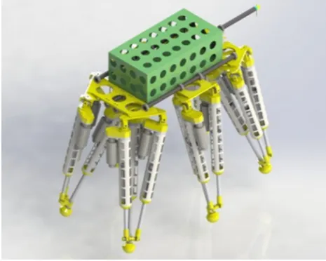
Parallel mechanisms have been researched intensively and applied widely [36–38]. But for robots with parallel legs, few related examples can be found [39,40]. The platform we study on is a six-parallel-legged robot as shown in Fig.1. The robot is a 6-DOF mobile platform with six legs arranged symmetrically along the sagittal plane of the body. Each leg of the robot is a 3-DOF parallel mechanism with three chains: one universal joint - prismatic joint (UP) chain, and two universal joint - prismatic joint - spherical joint (UPS) chains. The prismatic joint of each chain is the active input joint driven by a servo motor. A resolver is mounted to each motor to feedback the real position of the motor. At the head of the robot body, a 0-DOF tool with a 6D force sensor is mounted. The tool is composed of a horizontal rod and a vertical rod, which are parallel to the sagittal and vertical axis of the robot body respectively. The 6D force sensor is the ATI Mini58 IP68 F/T Sensor. Upside the body, a cabinet contains components of the onboard control system, including the battery, the onboard computer and the drivers.
Users control the robot by sending commands via a remote terminal unit, which communicates with the onboard computer via Wi-Fi. The resolvers provide the real positions of all motors, and the 6D force sensor feeds back the contact forces with the environments. The onboard
computer analyzes the positions and the forces data, and accordingly plans the trajectories of the body and the feet. According to the planed trajectories, the computer calcu-lates the parameters of all motors at every millisecond by running the real-time Linux OS. After the calculation, the onboard computer sends the parameters to the drivers via EtherCAT. Finally, each driver generates a current pro-portional to the received parameter and provides the cur-rent to drive the relevant motor.
3 Coordinate Systems and Kinematic Model
3.1 Coordinate Systems Definition
In order to well express the positional relationships among the door, the robot and the ground, it is essential to establish five coordinate systems (Figures2 and 3). The first one is the Robot Coordinate System(RCS), which locates at the center of the body and is fixed to the body.YR
andZR are parallel to the vertical and sagittal axis of the
body respectively. The second one is the Ground Coordi-nate System(GCS), which superposes the RCS at anywhere the user sets and is fixed to the ground. So the RCS moves together with the body and the GCS keeps still to the ground. Here the GCS is set to superpose the RCS as the door-opening task starts. The third one is the Door Coor-dinate System(DCS), which locates at the intersection of the handle axis and the door plane. The DCS is fixed to the door, withZD normal to the door plane andYDparallel to
the door hinge. The fourth one is the Leg Coordinate System(LCS), which locates at the Ui1 joint of the UP
chain and is fixed to the body. When Ui1 is at its initial
position where every prismatic joint of legishrinks to the shortest, XiL is along the prismatic joint, YiL and ZiL are
along the first and second axis ofUi1respectively. The LCS
Figure 1 Model of the six-parallel-legged robot
S41
S51
S61
S11
S21
S31
Q Door CS
ZD
YD
XD
OD
Robot CS
OR
XR
ZR
YR
Ground CS
ZG
YG
XG
OG
has a fixed relationship with the RCS defined by the geometry of the robot, which can be denoted by R
iLTði¼
1;2;. . .;6Þ: The fifth one is the Ankle Coordinate Sys-tem(ACS), which locates at each ankle with the same orientation as the LGS when Ui1 is at its initial position.
The ACS is fixed to the foot and moves as the leg moves.
3.2 Kinematic Model
Based on these coordinate systems, the kinematic model of the robot can be built in the GCS, which is indispensable for controlling the robot. The inverse kinematic model is essential for assigning the position value of each actuation in real time to generate the planed trajectories of the body and the feet, and the forward kinematic model is essential for calculating the real-time position of the robot.
As shown in Figure3, let si denote OiASi1, hi1 andhi2
denote the first and second angle ofUi1, 2dUiand 2dSidenote the lengths ofUi2Ui3andSi2Si3,hUiandhSidenote the dis-tances fromOiLtoUi2Ui3andOiAtoSi2Si3. LetLi(li1,li2,li3)T
denote the lengths ofUi1Si1,Ui2Si2andUi3Si3, which is the
input of legi. LetSi1(xi,yi,zi)Tdenote the coordinates of foot i, which is the output of legi. The output of the body can be denoted by the pose matrix of the RCS in the GCS:
G
RT¼
G
RR
GO
R
O13 I11
; ð1Þ
where GRT—Pose matrix of the RCS in the GCS,GRR— Orientation matrix of the RCS in the GCS,GOR—Origin of
the RCS expressed in the GCS.
3.2.1 Inverse Kinematic Model
When given the output of the coordinates of all six feet and the pose matrix of the RCS, the input of all prismatic joints can be calculated in real time by
lij¼ iiLAR
iAS
ijþiLOiAiLUij
2; ð2Þ
wherei—Leg number,i¼1;2;. . .;6;j—Chain number of leg i,j=1, 2, 3,
iL
iAR¼
coshi1coshi2 coshi1sinhi2 sinhi1
sinhi2 coshi2 0
sinhi1coshi2 sinhi1sinhi2 coshi1 0
@
1 A;
iAS
i1 iASi2 iASi3
¼
si 0 0 0 hSi hSi 0 dSi dSi
0 @
1 A;
iL
OiA¼
ffiffiffiffiffiffiffiffiffiffiffiffiffiffiffiffiffiffiffiffiffiffiffiffiffiffiffiffiffiffiffiffiffiffi
iLx2
i þiLy
2
i þiLz
2
i
q
si
coshi1coshi2
sinhi2
sinhi1coshi2 0
@
1 A;
iLU
i1 iLUi2 iLUi3
¼
0 0 0
0 hUi hUi 0 dUi dUi
0 @
1 A:
The hi1 andhi2 here can be calculated from the output G
RTand
GS
i1(Gxi,Gyi,Gzi)Tby
hi1 ¼arctan
iLz
i iLx
i
;
hi2 ¼arcsinð
iLy
i
ffiffiffiffiffiffiffiffiffiffiffiffiffiffiffiffiffiffiffiffiffiffiffiffiffiffiffiffiffiffiffiffiffiffi
iLx2
i þiLy2i þiLz2i
p Þ;
iLS
i1
1
¼R
iLT 1G
RT
1 GSi1
1
:
8 > > > > > > > < > > > > > > > :
ð3Þ
3.2.2 Forward Kinematic Model
When given the input of all prismatic joints, either the output coordinates of all six feet or the pose matrix of the RCS must be known so that the other one can be derived. If the pose matrix of the RCS is known, the output coordi-nates of all six feet can be expressed by
GS
i1
1
¼G RT
R
iLT
iLS
i1
1
;
iLS
i1¼iiLAR
iAS
i1þiLOiA; 8
<
: ð4Þ
wherei—Leg number,i¼1;2;. . .;6:
If the output coordinates of all six feet are known, the pose matrix of the RCS can be calculated by the coordinates of three stance-feet in 3-3 gait. Here we derive the equation using legs 1, 3, 5, and it is similar for legs 2, 4, 6: YiL
OiL
ZiL
XiL Leg CS
Si1 li1 li2
li3
OiA
XiA YiA
ZiA Si2 Si3 Ui1 Ui2
Ui3
Ankle CS OiA
Si2 Si3
2dSi
hSi
OiL
Ui2 Ui3
2dUi hUi
RS
i1¼RiLT
iL
iAR
iAS
i1þiLOiA
;
GS
i1GOR
2¼ RS
i1
k k2;
G
RR¼
GS
11GOR
GS
31GOR
GS
51GOR
0 @ 1 A T R S11 RS 31 RS 51 0 @ 1 A T ; 8 > > > > < > > > > :
ð5Þ
wherei—Leg number,i=1, 3, 5.
Here in Eqs. (4) and (5), the iiLAR, iLSi1 and iLOiA are
defined the same as in Eq. (2), but thehi1 andhi2 here are
calculated from the inputLi(li1,li2,li3)Tby
hi2¼arcsinð Þ xi arctan
hSi
li1si
;
hi1¼arcsin
/i
dUiððli1siÞcoshi2hSisinhi2Þ
; 8 > > < > > :
ð6Þ
where x4
i þaix3i þbixi2aixiþci¼0;
ai¼
2ui
hUi
ffiffiffiffiffiffiffiffiffiffiffiffiffiffiffiffiffiffiffiffiffiffiffiffiffiffiffiffi
li1si ð Þ2þh2
Si
q ;
bi¼ u2
i d
2 Uid
2 Si
h2
Ui ðli1siÞ
2
þh2 Si
1;
ci¼ /2id2
Siþ u
2
i d
2 Uid
2 Si
li1si ð Þ2þh2
Si
h2
Ui ðli1siÞ2þh2Si
2 ;
ui¼
li1si ð Þ2þd2
Uiþd2Siþh2Uiþh2Si
2
l2
i2þl2i3
4 ;
/i¼
l2
i2l 2 i3 4 : 8 > > > > > > > > > > > > > > > > > > > > > > < > > > > > > > > > > > > > > > > > > > > > > :
4 Door-opening Method
The approach of the door-opening method is shown in Figure4, which can also be applied to pull doors with some revisions on the trajectory planning. The task can be decomposed into five subtasks: locating the door, rotating to align, locating the handle, opening the door and walking through. Here we useQto denote the end-effecter of the tool, andQis fixed to the tool. The positions ofQat dif-ferent transients along the trajectory are marked by other letters, and these marks are fixed to the ground.
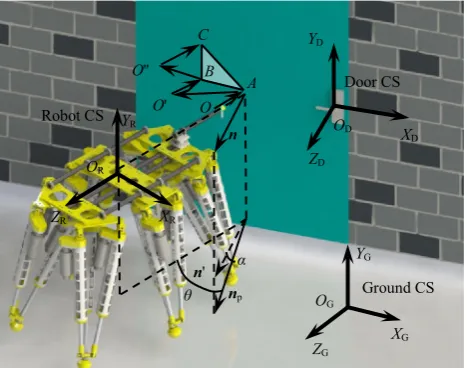
4.1 Locating the Door
The first subtask is locating the door (O?A?B ?C), in which the robot identifies the orientation matrix of the DCS in the GCS(GDR) by touching three non-collinear points on the door, as shown in Figure5.
Three non-collinear points define a plane. According to this basic principle, the robot firstly moves its body forward
(–ZR) until Q touches the first point A on the
door (O?A). Then, the robot moves its body both backward and leftward to a different point (A?O’), and forward again to touch the second point B(O’?B). Finally, the robot moves its body both backward and upward (B?O’’), and forward again to touch the third pointC(O’’?C). By making the backward and leftward distance duringAO’ equal, the backward and upward dis-tance duringBO’’ equal, the maximum angle between the sagittal axis of the robot body and the normal line of the door plane is allowed to be 45.
4.1.1 Trajectory Generation
The 6D trajectory of the robot body is generated by a discrete force control model:
MS€k¼FkCS_k1; _
Sk¼S_k1þS€kDt; Sk¼Sk1þS_kDt;
8 <
: ð7Þ
whereSk—6D coordinates of the robot body at time k,
Sk¼ðxk;yk;zk;ak;bk;ckÞ
T
;
Fk—6D force at timek, Task starts
Rotate to align Locate the door
Touch door
Change position
3
Locate the handle
Touch handle Rightward Legs follow Touch handle Downward N Y Touch door N Change direction to leftward Task ends If force exceeds
the limit
Task stops
Open the door
Turn handle
Push door
Walk through
Walk into door range
Walk through Adjust
Y
Fk¼ Fxk;Fyk;Fzk;Mxk;Myk;Mzk
T
;
M—Mass matrix,C—Damp matrix.
The robot determinesMandCaccording to the required accelerations and velocities, and generates different tra-jectories by applying different Fk. During locating the door, theFkis
Fk¼
G
RROð0;0;1ÞT
G
RROð0;0;0Þ
T
; if Q2OA[O0B[O00C;
G
RROð1;0;1ÞT
G
RROð0;0;0ÞT
; if Q2AO0;
G
RROð0;1;1Þ
T
G
RROð0;0;0Þ
T
; if Q2BO00;
8 > > > > > > > < > > > > > > > :
ð8Þ where G
RRO—GRR at point O, derived by Eq. (5),
Q2OA[O0B—Qis on line segmentOAorO’B.
4.1.2 Orientation Matrix Calculation
By applying Eq. (5), GOR at A, B, C can be derived and
denoted as GORA(xA, yA, zA)T, GORB(xB, yB, zB)T and GO
RC(xC, yC, zC)T. Let n(xn, yn, zn)T denote the normal vector of the door plane. Thenncan be calculated by
xAxB
yAyB
zAzB
xCxB
yCyB
zCzB
0 @
1 A
T G
xn
Gy
n
Gz
n
0 @
1
A¼0: ð9Þ
Transferring the vectornfrom the GCS to the RCS, we can get
Rx
n Ryn Rzn
T
¼GRR 1
O
Gn:
ð10Þ Then projectingn into theXRORZRplane, we can get Rn
p¼ ðRxn 0 RznÞ
T
: ð11Þ
Here the Tait-Bryan angle, which includes roll, pitch and yaw, is used to express the orientation of the DCS in the GCS. The yaw angle is
Ya¼h¼arctan Rx
n
Rz
n
: ð12Þ
Taking into account that there may be stairs or slopes along the direction ofZDin front of the door, making the
door plane not normal to the ground plane, the pitch angle exists betweennandnp:
Pi¼a¼ arcsin Ry
n n k k2
: ð13Þ
Considering there is nearly no doors with stairs or slopes along the direction ofXD, we can reasonably assume that
the roll angleRo¼0:
So, the orientation matrix can be calculated from the Tait-Bryan angle by
G
DR¼GRRODRRYX10Z00;
D
RRYX0Z00ðYa;Pi;RoÞ ¼
cosh sinhsina sinhcosa
0 cosa sina
sinh coshsina coshcosa
0 B @
1 C
A:
8 > > > < > > > :
ð14Þ
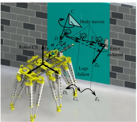
4.2 Rotating to Align
The second subtask is rotating aroundXRandYRto align
with the door plane (C?D). As shown in Figure 6, the robot moves its body, both transferring and rotating, from CtoD, and at the same time moves the feet to follow the body (CL?DL). The point OR atDsuperposesOR atO,
which determines the 6D trajectory as
CD¼
GO
ROGORC
Ro Pi Ya
ð ÞT
: ð15Þ
After the alignment, the horizontal rod of the tool will always keep normal to the door plane when the body translates, which guarantees the tool not to collide with the door plane during the process of locating the handle.
4.3 Locating the Handle
The third subtask is locating the han-dle (D?E?F?G), in which the robot identifies translational parameter GOD by three touches in three
orthogonal directions.
In order to touch the handle, the robot has to decide the height and the moving direction of the tool first. A
Door CS
ZD
YD
XD
OD
Robot CS
OR
XR
ZR
YR
O O'
O''
n'
np
n
Ground CS
ZG
YG
XG
OG
statistical analysis [15] of the most frequent size of handles shows that the height of the handle is in a range from 99 cm to 103 cm. Based on this acknowledgement, the robot keeps the vertical rod of the tool in this range. Then the robot chooses right as its target direction to touch the handle. If the robot confirms that the handle is not in the current direction, it changes its direction to left and per-forms the process of locating the handle again. Here we present the process of the localization and confirmation of the handle in the direction of right, and it is similar for left. As shown in Figure6, in case that the robot is far from the handle, the robot needs to move rightward cyclically. In every cycle except the final one, the robot successively moves the body forward (–ZR) until touching the door plane,
backward for a short constant distance to avoid rubbing with the door plane, rightward for a constant distance decided by the workspace of the tool, and moves the legs to follow the body, thus finishing the process ofD?E. The purpose of moving forward to touch and backward for a constant dis-tance at the beginning of every cycle is to initialize the
distance of the current cycle and eliminate the error accu-mulated in last one. When the robot starts too far from the handle, a very little angular error will cause a large transla-tional error along ZD, even though the robot has already
rotated to align. The large error makes it highly possible for the tool to fail to enter the space between the door and the handle considering its narrowness, thus failing to open the door. Because the distance of every rightward cycle is lim-ited to an acceptable constant value which will never be too far, the translational error along ZD can be limited well.
Furthermore, by applying multiple three-points contacts of locating the door and reducing the distance of every right-ward cycle, the detection accuracy can be guaranteed even if there are embossments or grooves on the door.
In the final cycle (E?F?Gin Figure7), after touching something at F, the robot moves its body leftward for a constant distance shorter than the handle, and downward to touch the handle. If the tool touches nothing until it gets lower than the minimum height, the robot treats it as a con-firmation that the handle is not in this direction. If the tool touches something, the robot treats it as a signal of suc-cessfully locating the handle and goes on to next subtask.
The trajectory is generated by Eq. (7) in every cycle. TheFkof every cycle duringD?Eis similar to theFkof E?Fin the final cycle, and in the final cycle theFkis
Fk¼
G
RREð0 0 1ÞT
G
RREð0 0 0Þ
T
;if Q2EE0;
G
RREð0 0 1ÞT
G
RREð0 0 0ÞT
;if Q2E0F0;
G
RREð1 0 0Þ
T
G
RREð0 0 0ÞT
;if Q2E0F0;
G
RREð1 0 0ÞT
G
RREð0 0 0Þ
T
;if Q2FG0;
G
RREð0 1 0ÞT
G
RREð0 0 0ÞT
;if Q2FG0:
8 > > > > > > > > > > > > > > > > < > > > > > > > > > > > > > > > > :
ð16Þ
The location of ODon the handle can be expressed by
Robot CS
OR
XR
ZR
YR n
F
ZD
Error reduced Body moves
Legs follow
L L
L
Figure 6 Rotating to align and approaching the handle
F
'
F'
'
dz
dy dx
Axis of the handle
OD
Door plane
Figure 7 Final cycle of locating the handle
I
y x
I
GO D
1
¼G RTE
RO
D
1
;
RO
D¼ROREþ
GO
RFGORF0
2
GO
RGGORG0
2
GO
REGORE0
2
0 B @
1 C A:
8 > > > > > < > > > > > :
ð17Þ
4.4 Opening the Door
The fourth subtask is opening the door (G?H?I), in which the robot firstly moves along a circular line in the door plane to turn the handle until it reaches the end (G?Hin Figure8), and then moves forward to try to push the door open (H?Iin Figure8). When moving forward, the robot keeps detecting the contact force. If it exceeds the maximum force the robot can apply, the robot treats it as a signal of door blocked and stops the task. The trajectories of turning and pushing are both generated by Eq. (7), and theFkis
Fk¼
G RRG sin
2vk
pr
cos 2vk
pr
0
T
G
RRGð0 0 0ÞT
0 B @
1 C
A;ifQ2_
GH;
G
RRGð0 0 1ÞT
G
RRGð0 0 0ÞT
!
;ifQ2HI;
8 > > > > > > > < > > > > > > > :
ð18Þ wherev—Average linear speed planed along the arc,r— Radius of the arc,Q2_
GH—Qis on the arc_GH.
The simpler mechanism of the 0-DOF tool plays a sig-nificant role here, in releasing the inner force in the tool when turning the handle. The open-loop structure of the end-ef-fecter cannot achieve a firm grasp of the handle like widely used closed-loop multi-DOF grippers, which takes a notably positive effect on the subtask but not negative, because the inner force is effectively released. The inner force occurs because the motion of the manipulator cannot follow the position of the handle exactly due to the positional error and the imprecise modeling of the door, while a firm grasp compels the manipulator to follow. And it is nearly impos-sible to completely solve this confliction only if a firm grasp is applied. However, the firm grasp is not essential for all cases. When applying the loose grasp, the contact point of the tool and the handle can slide along themselves, so that the tool does not have to follow the handle exactly, thus releasing the inner force. And because of the large areas the tool can move in (red areas in Figure8), it will not be a trouble for the tool to keep contacting with the handle when moving.
4.5 Walking Through
The fifth subtask is walking through(I?J?K?L), in which the robot adjusts its body back to the sagittal plane,
walks leftward into the door range, and then walks forward to get through the door (Figure9). The robot keeps detecting the contact force during the whole process. If the contact force exceeds the maximum force the robot can apply, the robot treats it as a signal of door blocked and stops the task.
When adjusting, the tool translates parallel to the wall plane (I?J) to release the handle and prepare for the left walking. The pointJis in the sagittal plane like the pointE, but higher thanEforhto avoid colliding with the handle, so the adjustment trajectory is
IJ¼
G RRI
G RRIRXR
T G
EGI
ð Þ
G RRIRYR
T G
EGI
ð Þ þh
0
0 B @
1 C A
G
RRIð0 0 0Þ
T 0
B B B @
1 C C C
A; ð19Þ
whereRXR;RYR—Basis vector ofX,Y-axis of the RCS,
RX
R¼ð1;0;0ÞT; RYR¼ð0;1;0ÞT;
GE;GI—Coordinates of pointE,Iin the GCS.
During the leftward walking, the robot keeps the end-effecterQtouching the door plane to prevent the door from closing automatically because of the door closer. Consid-ering the high load capacity, the robot can deal with doors with large rebounding forces. The trajectory is
I h
Feet trajectory Door trajectory
Body trajectory
L L
L
S41
JK¼
G RRJ
G RRJRXR
T G
ODGOR
ð Þ wR
2 0
0
0 B @
1 C A
G
RRJð0 0 0ÞT
0 B B B @
1 C C C A;
ð20Þ wherewR—Width of the robot.
During the process of walking forward, the robot uses its body to push the door open, making a good use of the high load capacity. The forward trajectory is
KL¼
G RRK
0 0
G RRKRZR
T GO
DGS41
ð Þ lR
0 @
1 A
G
RRKð0 0 0Þ
T 0
B B @
1 C C A;
ð21Þ whereRZ
R—Basis vector ofZ-axis of the RCS, R
ZR¼ð0;0;1Þ T
;
GS
41—Derived by Eq. (3),lR —Length of the robot.
5 Experiment Results
In order to verify the proposed method, experiments were carried out on the robot. The robot did not know the detailed parameters of the environment and autonomously planed its motion to open the door completely based on only the force feedbacks in real time. The unknown environment here means that the size of the door, the position of the handle, the required force et al. are all unknown. The door is 2025 mm high and 1130 mm wide, with a door closer to provide rebound tendency, as shown in Figure10. Figure11shows the process of opening the door in the experiment.
During locating the door, the robot adjusted its position to prepare for next touch every time when the force sensor detected a force pulse alongZRwhich indicated the robot had
already touched the door. The robot only moved its body to touch and kept its feet still on the ground. After detecting the third touch, the robot calculated the positional relationship with the door and rotated to keep the tool normal to the door plane. During the alignment, the robot moved both its body and feet. Figure 12shows the positions of the feet and the tool, and Figure13shows the force detected. Here we can use the motions of feet 2 and 5 to show the motions of all feet, because feet 2 and 5 move alternately in 3-3 gait.
Then, the robot moved rightward to touch the handle and made different decisions based on different force feedbacks. If no force pulse fed back, the robot moved its legs to follow the body. If the force pulse along XR was
detected, the robot knew it had touched the handle, and started to adjust its position to detect the handle alongYR.
During this process, the robot moved its body and feet separately. Figure14 shows the positions of the feet and the tool, and Figure15shows the force detected.
After detecting the force pulse along YR indicating that
the robot had touched the handle, the robot started to turn the handle. Once the force feedback from the handle Figure 10 Door and door closer in the experiments
exceeded the threshold indicating that the handle had reached the end, the robot moved forward to push the door open. Finally, the robot walked leftward into the door range
0 0.5 1 1.5 2 2.5 3 3.5 4 4.5
Time t/ms 104
-1 -0.7 -0.4 -0.1 0.2 0.5
Position
P
/m
Foot 2-X Foot 2-Y Foot 2-Z Foot 5-X Foot 5-Y Foot 5-Z Tool-X Tool-Y Tool-Z
Figure 12 Feet and tool positions during locating the door and rotating to align
0 0.5 1 1.5 2 2.5 3 3.5 4 4.5
Time t/ms 104
-15 -5 5 15 25 35
Force
F/N
Force-X Force-Y Force-Z
Figure 13 Feedback force during locating the door and rotating to align
3 4 5 6 7 8 9
Time t/ms 104
-1 -0.6 -0.2 0.2 0.6 1
Position
P
/m
Foot 2-X Foot 2-Y Foot 2-Z Foot 5-X Foot 5-Y Foot 5-Z Tool-X Tool-Y Tool-Z
Figure 14 Feet and tool positions during locating the handle
3 4 5 6 7 8 9
Time t/ms 104
-30 -20 -10 0 10 20 30
Force
F
/N
Force-X Force-Y Force-Z
Figure 15 Feedback force during locating the handle
7.5 8 8.5 9 9.5 10 10.5 11 11.5 12
Time t/ms 104
-2.5 -2 -1.5 -1 -0.5 0 0.5 1
Position
P/m
Foot 2-X Foot 2-Y Foot 2-Z Foot 5-X Foot 5-Y Foot 5-Z Tool-X Tool-Y Tool-Z
Figure 16 Feet and tool positions during turning the handle and walking through
7.5 8 8.5 9 9.5 10 10.5 11 11.5 12
Time t/ms 104
-105 -70 -35 0 35 70 105 140
Force
F
/N
Force-X Force-Y Force-Z
according to the calculated position of the handle and then walked through. Figure16shows the positions of the feet and the tool, and Figure17shows the force detected.
6 Conclusions
(1) The method of measuring the positional relationship between the robot and the door is developed, which uses only the force sensing and the 0-DOF tool to detect and open the door.
(2) The real-time trajectory planning method for the robot to open the door is proposed, which is completely based on the real-time measuring of the force sensing.
(3) The proposed door-opening method is implemented to the six-parallel-legged robot. Experiments are carried out to validate the method and the results show that the method is effective and robust in opening doors wider than the robot (1 m) in unknown environments.
Open Access This article is distributed under the terms of the Creative Commons Attribution 4.0 International License (http://crea tivecommons.org/licenses/by/4.0/), which permits unrestricted use, distribution, and reproduction in any medium, provided you give appropriate credit to the original author(s) and the source, provide a link to the Creative Commons license, and indicate if changes were made.
References
1. M H Raibert.Legged robots that balance. Cambridge: MIT press, 1986.
2. K Nagatani, S I Yuta. Designing a behavior to open a door and to pass through a door-way using a mobile robot equipped with a manipulator. Proceedings of the IEEE/RSJ/GI International Conference on Intelligent Robots and Systems, Munich, Ger-many, September 12–16, 1994: 847–853.
3. J Craft, J Wilson, W H Huang, et al. Aladdin: a semi-autonomous door opening system for EOD-class robots.Proceedings of the SPIE Unmanned Systems Technology XIII, Orlando, USA, April 25, 2011: 804509–1.
4. B Axelrod, W H Huang. Autonomous door opening and traversal.
Proceedings of the IEEE International Conference on the Tech-nologies for Practical Robot Applications, Boston, USA, May 11–12, 2015:1–6.
5. A Jain, C C Kemp. Behavior-based door opening with equilib-rium point control.Proceedings of the RSS Workshop on Mobile Manipulation in Human Environments. Seattle, USA, June 28, 2009: 1–8.
6. W Chung, C Rhee, Y Shim, et al. Door-opening control of a service robot using the multifingered robot hand. IEEE Trans-actions on Industrial Electronics, 2009, 56(10): 3975–3984.
7. D Kim, J H Kang, C S Hwang, et al. Mobile robot for door opening in a house.Proceedings of the International Conference on Knowledge-Based Intelligent Information and Engineering Systems, Wellington, New Zealand, September 20–25, 2004: 596–602.
8. H Arisumi, J R Chardonnet, K Yokoi. Whole-body motion of a humanoid robot for passing through a door-opening a door by impulsive force. Proceedings of the IEEE/RSJ International Conference on Intelligent Robots and Systems, Saint Louis, USA, October 11–15, 2009: 428–434.
9. M Zucker, Y Jun, B Killen, et al. Continuous trajectory opti-mization for autonomous humanoid door opening.Proceedings of the IEEE International Conference on Technologies for Practical Robot Applications, Boston, USA, April 22–23, 2013: 1–5. 10. N Banerjee, X C Long, R X Du, et al. Human-supervised control
of the ATLAS humanoid robot for traversing doors.Proceedings of the IEEE-RAS International Conference on Humanoid Robots, Seoul, Korea, November 3–5, 2015: 722–729.
11. J Lee, A Ajoudani, E M Hoffman, et al. Upper-body impedance control with variable stiffness for a door opening task. Pro-ceedings of the IEEE-RAS International Conference on Huma-noid Robots, Madrid, Spain, November 18–20, 2014: 713–719. 12. M Gonza´lez-Fierro, D Herna´ndez-Garcı´a, T Nanayakkara, et al.
Behavior sequencing based on demonstrations: a case of a humanoid opening a door while walking. Advanced Robotics, 2015, 29(5): 315–329.
13. E Ackerman.Boston Dynamics’ SpotMini Is All Electric, Agile, and Has a Capable Face-Arm. New York: IEEE Spectrum, 2016[2016-10-17]. http://spectrum.ieee.org/automaton/robotics/ home-robots/boston-dynamicsspotmini.
14. E Ackerman. Ghost Robotics’ Minitaur Quadruped Conquers
Stairs, Doors, and Fences and Is Somehow Affordable. New York: IEEE Spectrum. 2016[2016-10-17]. http://spectrum.ieee. org/automaton/robotics/roboticshardware/ghost-robotics-minitaur-quadruped.
15. J Moreno, D Martı´nez, M Tresanchez, et al. A combined approach to the problem of opening a door with an assistant mobile robot. Proceedings of the International Conference on Ubiquitous Computing & Ambient Intelligence. Belfast, Northern Ireland, December 2–5, 2014: 9–12.
16. E Klingbeil, A Saxena, A Y Ng. Learning to open new doors.
Proceedings of the IEEE/RSJ International Conference on Intelligent Robots and Systems, Taipei, Taiwan, October 18–22, 2010:2751–2757.
17. D Ignakov, G Okouneva, G J Liu. Localization of a door handle of unknown geometry using a single camera for door-opening with a mobile manipulator. Autonomous Robots, 2012, 33(4): 415–426.
18. A H Adiwahono, Y Chua, K P Tee, et al. Automated door opening scheme for non-holonomic mobile manipulator. Pro-ceedings of the International Conference on Control, Automation and Systems, Gwangju, Korea, October 20–23, 2013: 839–844. 19. A Petrovskaya, A Y Ng. Probabilistic mobile manipulation in
dynamic environments, with application to opening doors. Pro-ceedings of the International Joint Conference on Artificial Intelligence, Hyderabad, India, January 6–12, 2007: 2178–2184. 20. S Kobayashi, Y Kobayashi, Y Yamamoto, et al. Development of a door opening system on rescue robot for search ‘‘UMRS-2007’’.
Proceedings of the SICE Annual Conference, Tokyo, Japan, Augest 20–22, 2008: 2062 –2065.
21. T Winiarski, K Banachowicz, D Seredyn´ski. Multi-sensory feedback control in door approaching and opening.Proceedings of the International Conference on Intelligent Systems. Warsaw, Poland, September 24–26, 2014: 57–70.
22. A J Schmid, N Gorges, D Goger, et al. Opening a door with a
Proceedings of the International Conference on Robotics and Automation, Pasadena, USA, May 19–23, 2008: 285–291. 23. M Prats, P J Sanz, A P del Pobil. Reliable non-prehensile door
opening through the combination of vision, tactile and force feedback.Autonomous Robots, 2010, 29(2): 201–218.
24. Y Pan, F Gao, C K Qi, et al. Human-tracking strategies for a six-legged rescue robot based on distance and view.Chinese Journal of Mechanical Engineering, 2016, 29(2): 219–230.
25. F Farelo, R Alqasemi, R Dubey. Task-oriented control of a 9-DoF
WMRA System for opening a spring-loaded door task.
Pro-ceedings of the International Conference on Rehabilitation Robotics, Zurich, Switzerland, June 29–July 01, 2011: 1–6. 26. H W Zhang, Y G Liu, G J Liu. Multiple mode control of a
compact wrist with application to door opening.Mechatronics, 2013, 23(1): 10–20.
27. S Ahmad, G J Liu. A door opening method by modular re-con-figurable robot with joints working on passive and active modes.
Proceedings of the International Conference on Robotics and Automation, Anchorage, USA, May 03–08, 2010: 1480–1485. 28. S Ahmad, H W Zhang, G J Liu. Multiple working mode control
of door-opening with a mobile modular and reconfigurable robot.
IEEE/ASME Transactions on Mechatronics, 2013, 18(3): 833–844.
29. T Winiarski, K Banachowicz. Opening a door with a redundant impedance controlled robot. Proceedings of the Workshop on Robot Motion and Control, Kuslin, Poland, July 03–05, 2013: 221–226.
30. Y Karayiannidis, C Smith, P O¨ gren, et al. Adaptive force/velocity control for opening unknown doors. Proceedings of the Inter-national IFAC Symposium on Robot Control, Dubrovnik, Croatia, September 05–07, 2012: 753 –758.
31. W Guo, J C Wang, W D Chen. A manipulability improving scheme for opening unknown doors with mobile manipulator.
Proceedings of the International Conference on Robotics and Biomimetics, Hanoi, Vietnam, December 5–10, 2014: 1362–1367.
32. T Ru¨hr, J Sturm, D Pangercic, et al. A generalized framework for opening doors and drawers in kitchen environments.Proceedings of the International Conference on Robotics and Automation, Saint Paul, USA, May 14–18, 2012: 3852–3858.
33. S Chitta, B Cohen, M Likhachev. Planning for autonomous door opening with a mobile manipulator.Proceedings of the Interna-tional Conference on Robotics and Automation, Anchorage, USA, May 03–08, 2010: 1799–1806.
34. Y Pan, F Gao. A new 6-parallel-legged walking robot for drilling
holes on the fuselage. Proceedings of the Institution of
Mechanical Engineers, Part C: Journal of Mechanical Engi-neering Science, 2014, 228(4): 753–764.
35. Y L Xu, F Gao, Y Pan, et al. Method for six-legged robot step-ping on obstacles by indirect force estimation.Chinese Journal of Mechanical Engineering, 2016, 29(4): 669–679.
36. J He, F Gao, X D Meng, et al. Type synthesis for 4-DOF parallel
press mechanism using GF set theory. Chinese Journal of
Mechanical Engineering, 2015, 28(4): 851–859.
37. C Z Wang, Y F Fang, S Guo. Multi-objective optimization of a parallel ankle rehabilitation robot using modified differential evolution algorithm. Chinese Journal of Mechanical Engineer-ing, 2015, 28(4): 702–715.
38. H B Qu, Y F Fang, S Guo. Theory of degrees of freedom for parallel mechanisms with three spherical joints and its applica-tions.Chinese Journal of Mechanical Engineering, 2015, 28(4): 737–746.
39. X L Ding, K Xu. Gait analysis of a radial symmetrical hexapod
robot based on parallel mechanisms. Chinese Journal of
Mechanical Engineering, 2014, 27(5): 867–879.
40. M F Wang, M Ceccarelli. Topology search of 3-DOF transla-tional parallel manipulators with three identical limbs for leg mechanisms.Chinese Journal of Mechanical Engineering, 2015, 28(4): 666–675.
Zhi-Jun Chen, born in 1991, is currently a PhD candidate atState Key Laboratory of Mechanical System and Vibration, Shanghai Jiao Tong University, Shanghai, China. He received his bachelor degree fromShanghai Jiao Tong University, China, in 2013. His research interests include control and trajectory plan of legged robots. Tel: ?86-15821788367; E-mail: [email protected]
Feng Gao, born in 1956, is currently a professor at State Key Laboratory of Mechanical System and Vibration, Shanghai Jiao Tong University, Shanghai, China. He received his PhD degree from
Beihang University, China, in 1991. His main research interests include parallel robots, design theory and its applications, large scale and heavy payload manipulator design, large scale press machine design and optimization, design and manufactory of nuclear power
equipment, legged robots design and control. E-mail: