ORIGINAL ARTICLE
Optimal Design and Force Control
of a Nine-Cable-Driven Parallel Mechanism
for Lunar Takeoff Simulation
Wangmin Yi
1,2,3*, Yu Zheng
2,4, Weifang Wang
5, Xiaoqiang Tang
1, Xinjun Liu
1and Fanwei Meng
2,3Abstract
Traditional simulation methods are unable to meet the requirements of lunar takeoff simulations, such as high force output precision, low cost, and repeated use. Considering that cable-driven parallel mechanisms have the advan-tages of high payload to weight ratio, potentially large workspace, and high-speed motion, these mechanisms have the potential to be used for lunar takeoff simulations. Thus, this paper presents a parallel mechanism driven by nine cables. The purpose of this study is to optimize the dimensions of the cable-driven parallel mechanism to meet dynamic workspace requirements under cable tension constraints. The dynamic workspace requirements are derived from the kinematical function requests of the lunar takeoff simulation equipment. Experimental design and response surface methods are adopted for building the surrogate mathematical model linking the optimal variables and the optimization indices. A set of dimensional parameters are determined by analyzing the surrogate mathematical model. The volume of the dynamic workspace increased by 46% after optimization. Besides, a force control method is proposed for calculating output vector and sinusoidal forces. A force control loop is introduced into the traditional position control loop to adjust the cable force precisely, while controlling the cable length. The effectiveness of the proposed control method is verified through experiments. A 5% vector output accuracy and 12 Hz undulation force output can be realized. This paper proposes a cable-driven parallel mechanism which can be used for lunar takeoff simulation.
Keywords: Force control, Lunar takeoff simulation, Parallel robots, Surrogate mathematical model
© The Author(s) 2019. This article is distributed under the terms of the Creative Commons Attribution 4.0 International License (http://creat iveco mmons .org/licen ses/by/4.0/), which permits unrestricted use, distribution, and reproduction in any medium, provided you give appropriate credit to the original author(s) and the source, provide a link to the Creative Commons license, and indicate if changes were made.
1 Introduction
In the third phase of the Chinese lunar exploration pro-ject, the verification of lunar takeoff technology will be completed by Chang’e V probe [1]. During the initial phase of takeoff, because sufficient initial values of iner-tial measurements cannot be obtained, the guidance, navigation, and control system does not function in con-trolling the reentry capsule. Thus, the successful launch of the reentry capsule depends heavily on the launcher design, which should be verified by ground experiments. Therefore, a ground experimental device needs to be set up to precisely simulate the low-gravity environment on
the lunar surface, the thrust of the engine, and the dis-turbing force.
Currently, the available methods for simulating the low-gravity environment on the lunar surface could be classified into four categories, namely, the inertia com-pensation method [2], the buoyancy balance method [3], the rigidity parallel mechanism simulation method [4], and the sling suspension method [5]. The inertia com-pensation method is limited by short simulation time and high cost. The buoyancy balance method can establish a broad range of stable low-gravity environments, but the dynamic performances of the test objects are severely affected by water. The workspace of the rigid paral-lel mechanism is too small, while the sling suspension method can only support force along one direction. Con-sidering that cable-driven parallel mechanisms (CDPMs) have the advantages of high payload to weight ratio,
Open Access
*Correspondence: [email protected]
1 Department of Mechanical Engineering, Tsinghua University, Beijing 100084, China
potentially large workspace, and high-speed motion [6], a parallel mechanism driven by nine cables is proposed for lunar takeoff simulation.
To perform lunar takeoff simulation experiments, a CDPM should have enough workspace to output the desired resultant force with high precision. The work-space of the CDPM is surrounded by a convex hull that is made up of fixed points [7]. The objectives of this study are to optimize the dimensions of the CDPM to meet the workspace requirements, and to design a control method to meet the force accuracy requirements.
So far, substantial progress has been made in the design of CDPMs. In Ref. [8], Ming pointed out that a cable sys-tem with j end-effector DOFs requires at least i=j+ 1 cables, since the cable can only be in tension. Verhoeven [9] studied the feasible workspace considering pull and stiffness conditions. Gosselin focused on the dynamic workspace in solving the dynamic trajectory planning problem [10]. Merlet [11] proposed an algorithm to determine a polygonal approximation of the workspace border induced by a specific constraint. Previous stud-ies on dimensional optimization design were based on workspace requirements, and the constraint condition was derived from tension and stiffness requirements [12– 14], which will greatly influence the accuracy of CDPMs. Tang et al. [15] proposed stiffness and tension may be considered as a whole to evaluate the workspace qual-ity. Tension distribution is another issue in the study of CDPM. Researchers have taken advantage of the convex method [16], tension-level index [17], and gradient pro-jection [18] to distribute tension.
Unlike previous studies, for the CDPM proposed in this paper, the distribution of cables is relatively concentrated, which means that the interactions among design vari-ables can not be neglected. The response surface method (RSM) [19–21] is a multiparameter optimization method that is based on the concept of building a surrogate math-ematical model to quantitatively describe the interac-tions among the design variables, and the relainterac-tionship between the design variables and the performance index. To obtain a more accurate surrogate mathematical model with fewer test points, the experimental design method (DOE) is used to lay out the location of the sample points [21]. Thus, the first contribution of this study is the pro-posal of a novel optimization procedure based on the DOE and RSM to drive the structure of the CDPM for a given task.
The most frequently used control strategy is to control the cable length (or the angle of motor): a feedback con-trol in the cable length is used for coordination to real-ize the desired cable length corresponding to a desired position of an end-effector. Motion convergence, using PD feedback control in the cable length coordinates, was
proven with a Lyapunov function and Vector Closure by Kawamura et al. [22]. Fang et al. [23] proposed nonlinear feedback control laws in cable length coordinates, and the optimal tension distribution was considered to the advantage of the control laws. Werner et al. established an analogous model of the CDPM, then identified system parameters, pulley friction, and load, and finally imple-mented feed-forward and integral controllers to improve control accuracy [24, 25]. Other reported algorithms used in the control of CDPMs are composite control [26], computed torque control [27], robust PID control [28], and adaptive control [29]. However, previous stud-ies could not meet the tension accuracy requirements for lunar takeoff simulation. In this study, a force loop is introduced into the traditional position control loop, and the force loop is used for the precise adjustment of tension.
The remainder of this paper is organized into six sec-tions. In Section 2, we give the function requirements and a hardware overview of the CDPM. A kinematic model of the CDPM and an iterative program to calculate its workspace are given in Section 3. In Section 4, a sur-rogate mathematical model linking the structure param-eters and the dynamic workspace is built based on the DOE and RSM. A set of optimized dimensional param-eters can be obtained by analyzing the surrogate math-ematical model. In Section 5, a hybrid force and position control method is proposed to improve the force accu-racy. The prototype and experimental results of the pro-posed control method are presented in Section 6. Finally, conclusions and an outlook are given in Section 7.
2 Task Analysis and System Overview
Given the quality of the reentry capsule, the gravity data on the lunar surface, and the thrust data on the thruster, we can obtain the acceleration, velocity, and other param-eters of the reentry capsule during the initial phase of takeoff. The maximum vertical acceleration is 2.314 m/s2,
and the maximum horizontal acceleration is 1.021 m/s2.
Therefore, the CDPM should be able to output the desired resultant force.
The index of the CDPM is derived from the scaled index of the real takeoff progress. The scaling ratios we adopted are listed as follows:
(1) The scaling ratio of acceleration is 1:1. (2) The scaling ratio of the workspace is 1:4.
(3) The scaling ratio of quality should be the cube of the scaling ratio of the workspace. Therefore, the scaling ratio of quality is set as 1:64.
(4) From the equation h= 0.5at2, the square of the
effec-tive working time is 1:2, and the effeceffec-tive working time of the CDPM is set as one second.
According to the abovementioned requirements, the function requests of the CDPM are listed next. Con-sidering the accuracy and real-time requirements, some indexes are added to a certain margin.
(1) The maximum load is 20 kg.
(2) The maximum vertical acceleration is 2.4 m/s2, and
the maximum horizontal acceleration is 1.1 m/s2.
(3) The error of the resultant force is less than 5%. (4) The moving platform should have six degrees of
freedom.
Based on the abovementioned requirements, the CDPM should output the force with high precision and have enough dynamic workspace to output the desired acceleration for the desired time. The maximum qual-ity, the maximum desired vertical acceleration, and the maximum desired horizontal acceleration of the mov-ing platform are set as 20 kg, 2.4 m/s2, and ± 1.1 m/
s2 respectively. Integrating the acceleration and the
velocity over time, and taking the safe distance of brak-ing into consideration, the dynamic workspace should contain a cylindrical area of Ф1.4 m × 2.4 m and be as large as possible. In this study, we adopt the defini-tion of dynamic workspace as presented in Ref. [30]. In order to achieve six-DOF motion control of the mov-ing platform, at least seven cables are required. Redun-dant cables can optimize the dynamic workspace and attitude control ability of the CDPM, but more cables will increase the difficulty of controlling the mecha-nism precisely.
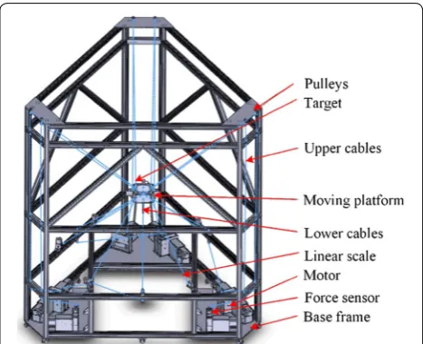
In this study, a nine-cable-driven parallel mecha-nism is introduced to perform the lunar takeoff simulation experiments. Figure 1 shows a schematic diagram of the nine-cable-driven parallel mechanism, in which the layout of connection points on the mov-ing platform is “6-3” [31]. The lower three cables are directly connected to the winches, while the upper six cables go through pulleys connected to the winches on the bottom. The motion of the moving platform is realized by the upper six cables, and the lower 3 cables are used to exert the disturbing force.
The dimensional parameters can greatly affect the dynamic workspace. Thus, the “optimal design” in this study aims at obtaining a better set of dimension parameters for the CDPM to meet dynamic workspace requirements under cable tension constraints.
3 Kinematics and Workspace Calculation
As shown in Figure 2, two coordinates are set up in the nine-cable-driven parallel mechanism: the global frame
Figure 1 Schematic diagram of proposed nine-cable-driven parallel mechanism
Kb is fixed at the base frame and the moving frame Kp is
connected to the moving platform. The symbols used in this paper are defined as follows: Bi (i= 1, 2,…, 9)
repre-sent the cable installation positions on the base frame, and Pi (i= 1, 2, …, 9) denote the cable installation
posi-tions on the moving platform. Vectors pi (i= 1, 2, …, 9)
represent the vectors connecting point o′ to points Pi,
and bi represent vectors connecting point o to points Bi. fi (i= 1, 2, …, 9) are defined as the cable tension
vectors along the i cables. fp and τp represent external
forces (except gravity) and torques acting on the plat-form. The position of the center of the end-effector in the fixed base frame Kb is defined as op= (x,y,z), and
the posture of the moving platform in Kb is defined as
(Ψ,Φ,γ). Defining R as the transformation matrix from
Kp to Kb, the expression for R is given in Eq. (1):
In Eq. (1), sΨ = sin(Ψ), cΨ = cos(Ψ), and the remaining variables are as defined previously.
The unit vector along the ith cable can be expressed as
The force and torque equilibrium for the platform can be written as
where t = [t1, t2, …, t9]T, w = [fp+ mg, τp]T, and
AT=
u1
p1×u1
· · · · · ·
u9
p9×u9
.
Considering the acceleration requirements of the mov-ing platform, the expression for fp is given in Eq. (4):
According to the parameters set in Section 2,
a1=± 1.1 m/s2, a2=± 1.1 m/s2, m= 20 kg, a3= 2.4 m/s2,
and τp= [0, 0, 0]T N·m.
To study the dynamic workspace of the CDPM, Eq. (4) must be solved. A pose is part of the dynamic work-space only if a tension distribution result t exists, and
tmax≥t≥tmin > 0, where tmax is the maximum tension and
tmin is the minimum tension. The method first proposed
by Lafourcade [32] is adopted in this study to solve Eq. (4), and the solution is shown in Eq. (5):
(1)
R=
cΦcγ −cΦsγ sΦ
sΨsΦcγ+cΨsγ −sΨsΦsγ+cΨcγ −sΨcΦ −cΨsΦcγ+sΨsγ cΨsΦsγ+sΨsγ cΨcΦ
.
(2)
ui= li
|li|
= bi−op−R·pi bi−op−R·pi .
(3)
AT·t+w=0,
(4)
fp=−ma1 −ma2 −ma3T .
(5)
t= −
AT+·w+
Im×m−
AT+AT
·td,
where td= [tdtdtdtdtdtdtdtdtd]T, (AT)+ is the MP inverse
of AT. The value of each element in t
d is identical because
the nine-cable-driven parallel mechanism is designed with modular parts.
Therefore, the dynamic workspace of the nine-cable-driven parallel mechanism can be determined using the following algorithm based on the Monte-Carlo method:
(1) The convex set of the frame is divided uniformly into 64000 parts. The center of each part is consid-ered as a sample point.
(2) Choose a sample point. (3) Calculate structure matrix AT.
(4) Choose a desired tension td.
(5)
(6) If tmax≥t≥tmin > 0, the chosen sample point belongs
to the dynamic workspace. Otherwise, ignore the chosen sample point.
(7) Repeat (2)–(5) until all sample points are calculated.
4 Optimal Design
Most of the previous studies used a single-factor method to optimize the structure of the CDPM. For the CDPM proposed in this paper, the distribution of cables is rela-tively concentrated. Thus, the interactions among the design variables, which cannot be investigated with a single-factor method, would influence the dynamic workspace. To overcome the abovementioned shortcom-ing, we used the DOE to select experimental points and the RSM to build a surrogate mathematical model link-ing the structure variables and the performance indices. Then, by analyzing the surrogate mathematical model, the optimized variables were obtained while considering the interactions among the variables.
In this paper, we define the variable SUM_DWS as the number of sample points belonging to the dynamic workspace. The positions Bi (i = 1, 2, …, 9) are distributed
around a circle with a radius of 2 m, the height of the moving platform is 0.75 m, and the height of the whole system is 3.5 m. Bi are y axial symmetry in Kb, and Pi are y axial symmetry in Kp. The circle formed by Bi and that
formed by Pi are similar.
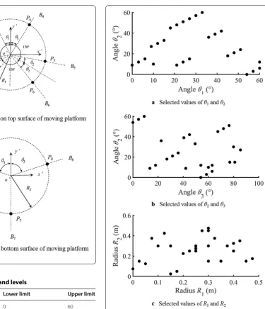
θi (i = 1, 2, 3), R1, and R2 define the optimal variables.
These variables are shown in Figure 3, and the range of values for each variable is given in Table 1.
The Latin-hypercube method [33] was used to select the experimental points. This method is based on the principle of random probability orthogonal distribu-tion. Thus, a response surface model with high precision
t= −
AT +
·w+ Im×m− AT + AT
can be obtained using fewer experimental points. The selected experimental points are shown in Figure 4.
A quadratic polynomial response surface model, as shown in Eq. (6), is used to establish the surrogate mathematical model linking the optimal variables and SUM_DWS.
(6)
y(x)=β0+
n
i=1
βixi+ n
i=1
βiix2i + n−1
i=1
n
j=i+1
βijxixj.
In Eq. (6), y(x) is the predictive value of the response sur-face model, xi is the ith component of the n-dimensional
independent variable. β0, βi, βii, and βij are the coefficients
of the polynomial, which are calculated by the least squares method. The surrogate mathematical model linking the optimal variables and the output response is given in Eq. (7):
(7)
SUM_DWS=1534.18+1167.49θ1+216.88θ2+50.07θ3
−107236R1−34549.82R2−14.56θ1θ2
−6.39θ1θ3−3980.62θ1R1−679.51θ1R2
−0.19θ2θ3+1370.92θ2R1+914.24θ2R2
+879.23θ3R1+234.25θ3R2−68441.92R1R2
+7.67θ12−5.32θ22−0.97θ32+309322R12
−20260.13R22.
Figure 3 Optimal variables
Table 1 Variable names and levels
Variable name Lower limit Upper limit
θ1 (°) 0 60
θ2 (°) 0 60
θ3 (°) 0 90
R1 (m) 0 0.5
R2 (m) 0 0.5
The determinant coefficient R2 and multiple fitting
coefficient R2
adj are used to verify the surrogate
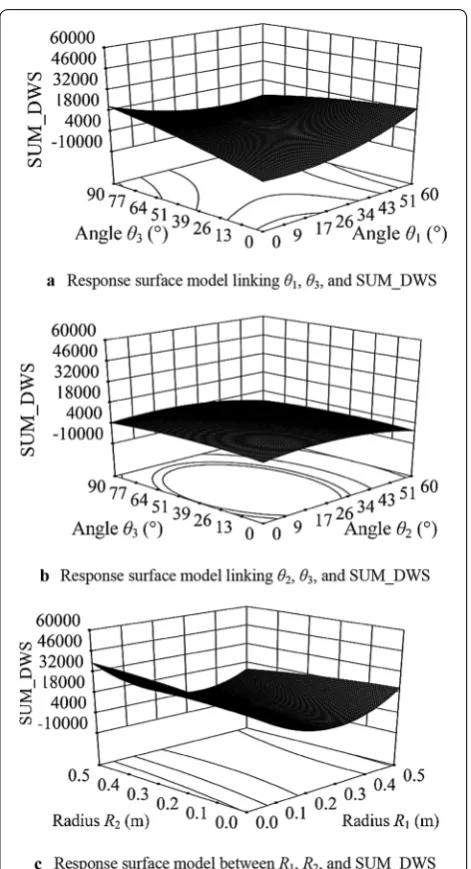
math-ematical model, and the calibration results are shown in Table 2. Considering the whole response surface model as a hypersurface in a multidimensional space, we divide the response surface model into three 3-D response surface models, as shown in Figure 5. From Table 2, we can con-clude that the response surface model meets the accuracy requirements. The mathematical relationship between the variables and the output can be approximated by a quadratic polynomial response surface.
Multiple sets of optimal solutions were obtained by searching for the maximum of the surrogate mathemati-cal model. Then, the set of final optimized dimensional parameters were obtained while considering some restrictions on production, processing, and installations. Five groups of optimal solutions are shown in Table 3. The final optimized results are shown in the last line of Table 3.
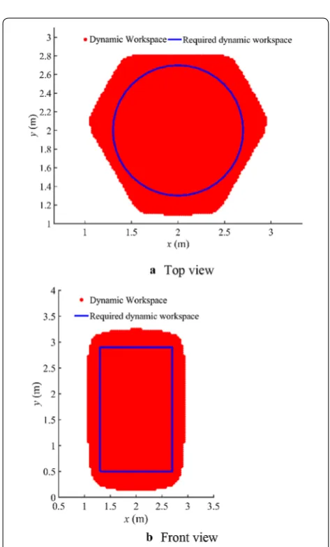
After optimization, the dynamic workspace of the CDPM is shown in Figure 6. Figure 6 indicates that the dynamic workspace can meet the requirements. The comparison of variables before and after optimization are listed in Table 4, which indicates that the volume of the dynamic workspace increases by 46% after optimization. These optimized dimensional parameters will be applied in the construction of the CDPM.
5 Hybrid Force and Position Control Method
In this study, the CDPM was built to simulate the low-gravity environment on the lunar surface, the engine thrust, and the disturbing force. The gravity and the thrust can be considered as vector forces, while the dis-turbing force can be considered as a linear combination of sinusoidal forces at different frequencies. Thus, the CDPM should have the capacity to output a vector force and a sinusoidal force with high precision. Therefore, in this study, the resultant force of nine cables was set as the control target instead of the pose of the moving platform. Only the cable length can be controlled. The tension can-not be controlled precisely. The system could easily go out of control if only the tension is controlled. Therefore, this paper proposes a hybrid force and position control method that introduces a force feedback signal into the position control circuit of the cable drive unit. The force controller can adjust the tightness of the cable slightly,
based on the cable force signals and the anticipated cable force, so as to control the cable force. The algorithm flow of the hybrid force and position control method is shown in Figure 7.
In each control cycle, the controller calculates the pose of the moving platform according to the pose sensor data. Then, the structure matrix AT is computed. According to
the expected pose (xdydzdΨd, Φd, γd) of the moving
plat-form and the expected resultant force wd, the expected
cable length Ld and the expected cable force td are
cal-culated. The force controller calculates the force control signal Δl according to the tension error e. The cable drive unit overlays the force control signal Δl, the expected
Table 2 Calibration results
Optimal variable Determinant coefficients
R2 Multiple fitting coefficient R2 adj
SUM_DWS 0.9891 0.9617
length Ld and the actual length L, and completes the
con-trol of the cable length and cable force.
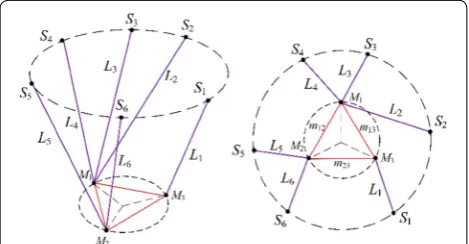
Six linear scales and six wire encoders are used to measure the pose of the moving platform, which can be calculated using the forward kinematics algorithm for the Stewart parallel mechanism. The layout of the lin-ear scales and the wire encoders are shown in Figure 8, in which Si (i= 1, 2, …, 6) represent the installation
posi-tions of the wire encoders, Li (i= 1, 2, …, 6) represent
the lengths of the linear scales, Mi (i= 1, 2, 3) represent
the measurement points on the moving platform, and mi
(i= 12, 13, 23) represent the lengths between the meas-urement points.
The forward kinematic model of the Stewart parallel mechanism is given in Eq. (8). Vectors mi represent the
vectors connecting point o’′ to points Mi, and si represent
the vectors connecting point o to point Si. In Eq. (8), R
and op are as defined in Section 3:
In Eq. (8), |Li|, mi, and si are known. The Newton–
Raphson algorithm, which is shown in Eq. (9), is used to calculate the pose of the moving platform:
The expected acceleration in each control cycle can be determined based on the expected resultant force wd
and the load mass m. By integrating the expected accel-eration with time, the expected pose (xdydzdΨd, Φd, γd)
of the moving platform could be calculated. Defining
opd= [xd, yd, zd]T, Ψd, Φd, and γd are used to calculate
Rd. Then the expected length Ld is obtained according
(8)
|Li| = |Rmi+op−si|.
(9)
x(k+1)=x(k)−F′x(k)−1Fx(k),(k=0, 1,· · ·). Table 3 Optimal solutions
Angle θ1 (°) Angle θ2 (°) Angle θ3 (°) Radius R1 (m) Radius R2 (m) SUM_DWS
1 3.25 6.62 57.56 0.26 0.05 8559.6
2 4.73 3.61 77.06 0.25 0.11 7478.7
3 5.85 6.17 62.59 0.23 0.08 7343.9
4 4.82 8.03 53.24 0.28 0.11 7554
5 2.69 4.76 54.77 0.29 0.11 8065.4
6 5 5 60 0.25 0.1 6551
Figure 6 Directional views of dynamic workspace
Table 4 Comparison of variables before and after optimization
Angle θ1 (°) Angle θ2 (°) Angle θ3 (°) Radius R1 (m) Radius R2 (m) SUM_DWS
Before optimization 30 30 30 0.2 0.2 4397
to Eq. (10). The permanent magnet synchronous motor (PMSM) in the drive unit drives the ropes to reach the desired lengths. Thus, the rough adjustment of tension is realized. The PMSM has a “current-speed-position” cascade control structure.
Meanwhile, according to the pose and the desired resultant force, the desired tension td in each control
cycle can be calculated. In the elastic range, the rela-tionship between tension change dFi and axial strain
dli/li is given in Eq. (11):
For the CDPM examined in this study, the diameter of the cable is 0.5 mm, and the modulus of elasticity is 206 GPa. Thus, if the tension changes by 5 N, the rope deforms by 0.1 mm. Therefore, control of the tension
(10)
Ld=
|l1d| |l2d| · · · |l9d|
T
,
|lid| =
bi−opd−Rd·pi
, (i=1, 2,. . ., 9).
(11)
dFi=
ES li
dli.
can be achieved by slightly controlling the deformation of the rope.
The force controller tightens or relaxes the rope based on the tension error e, so that the expected tension is achieved. The control strategy is given in Eq. (12). The precise adjust-ment of tension is realized.
The force distribution method is described next. The force distribution results are determined by Eq. (13):
where,
The desired tension of the lower cable should be set at a fixed value:
Equation (16) is derived by substituting tdown into Eq. (3):
After setting the tension of the lower cables as positive, the configuration of the nine-cable-driven parallel mecha-nism determines that the tension of upper cables is positive and the inverse matrix of J(6×6) exists. Thus, the force
distri-bution results of upper cables are determined by Eq. (17):
In the abovementioned force contribution method, the desired tension of the lower cables is set at fixed value to
(12)
�l=
0.05 mm, e<0,
tighten rope
, −0.05 mm,e>0, (relax rope).
(13)
t=tup+tdown,
(14)
tup=
t1 · · · t6 0 0 0
T
,
tdown=
01×6 t7 t8 t9
T . (15) t′ down=
t7 t8 t9T=tpre,7 tpre,8 tpre,9T.
(16)
J(6×6)t′up=w′.
(17)
t′
up=J −1
(6×6)w
′=
t1 · · · t6T.
Tension sensor Pose sensor Newton-Raphson Method PMSM Velocity Loop PID Controller Position Loop PID Controller (AT)
-Force distribution Force controller + -Desired tension Td Actual tension T Force control
signals Ƹl Actual length L
Measurement results dl Pose of the
moving platform
Desired Resultant Force w
Current Loop PID Controller
Drive unit
CDPM
1/ms2 AT
Desired length Ld + Desired pose of the
moving platform +
-+ -wd w τd τ + -e
Figure 7 Control diagram
decrease the difficulty of control. Besides, the force dis-tribution results can be adjusted by adjusting the preload value of the lower cables.
6 Force Control Experiment 6.1 Prototype Design
The prototype of the nine-cable-driven parallel mecha-nism is shown in Figure 9. The experimental platform consists of six parts: the basic frame, the drive unit, the force measurement module, the pose measurement module, the electrical control circuit, and the control software.
The aluminum alloy base frame is used to support and install the drive units, sensors, electrical circuits, and other hardware equipment.
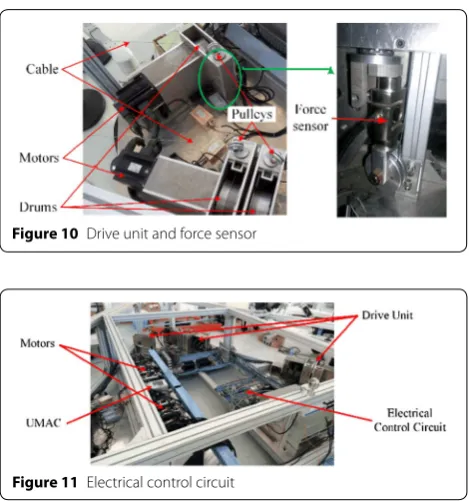
The drive unit, shown in Figure 10, rotates the drum using the servo motor. A cable guiding device is included in the drive unit to ensure that the cable winding is not involved, and to reduce the friction force at the same time. The S-shaped cable guide channel and pulley are also used for cable guidance.
The S type tension sensor is selected for the experimen-tal platform and is insexperimen-talled at the guidance channel. The tension sensor and its installation position are also shown in Figure 10. The accuracy class of the tension sensor is 0.3%.
The pose measurement module includes six linear scales and six wire encoders with the Stewart configura-tion layout. The standard resoluconfigura-tion of the wire encoder is 0.05 mm per pulse, and the accuracy of the wire encoder is ± 0.05% FS.
The core of the electrical control circuit, as shown in Figure 11, is the Turbo PMAC multi-axis controller from
Delta Tau Data Systems, Inc. The electrical circuit per-forms the functions of servo control, data acquisition of the force measurement and pose measurement modules, and load control.
6.2 Experimental Results
In this section, we briefly present the results of the force control experiments. First, the results of the constant vector force output experiments are presented. The experimental conditions were set as follows: the initial posture of the moving platform was (0°, 0°, 0°), the mov-ing platform moved upwards vertically with an accelera-tion of 0.3 m/s2, the quality of the moving platform was
20 kg, the test time was 3 s, and the control frequency was 500 Hz.
Figure 12 shows the results of the constant vector force output experiments. Figure 12(a) indicates that the error of the joint force is less than 5%. The desired and actual tensions are shown in Figure 12(b)–(d). The tensions of the upper six cables match with the expected values. The overall deviation in the tension of the upper six cables is caused by system errors, such as the deviation between the actual value and the theoretical value of the structure size, the quality of the load, and the moving platform. The tensions of the lower three cables fluctuate around the set values, and the fluctuation is less than 1.5 N.
The results of the disturbing-force output experi-ments are given in Figure 13. In these experiments, the force/position hybrid control method is used to control the lower cable to output periodic wave forces at differ-ent frequencies. The desired tension is set to a constant Figure 9 Nine-cable-driven parallel mechanism
Figure 10 Drive unit and force sensor
force of 30 N with the periodic fluctuations, and the amplitude of the undulation force is 6 N.
For wave forces of 2, 3, and 5 Hz, the fluctuation of the actual output cable force is about 5.5, 6, and 7.5 N, respectively. In the case of the 5 Hz wave force, the actual
Figure 12 Results of constant vector force output experiments
measurement glitch is larger, presumably because the inherent frequency of the cable-force-and-cable paral-lel mechanism is quite close to that of vibration cou-pling. For the wave force of 9 Hz, the fluctuation of the actual output cable force is about 7.3 N, and correspond-ing measurement glitch is relatively small. Similarly, for the wave force of 12 Hz, the actual output fluctuation is about 4.5 N, and both the cable-force average and the corresponding amplitude are less than the respective the-oretical values.
The series of disturbing-force experimental results show that the hybrid force and position hybrid control method can control cable-force fluctuations within a certain range of frequencies. When the target cable-force fluctuation frequency is controlled from 5 Hz to 9 Hz, the actual output cable-force fluctuation ampli-tude is slightly larger than that of the theoretical input. When the target cable-force frequency is less than 5 Hz or more than 9 Hz, the actual output cable-force fluc-tuation amplitude is smaller than that of the theoretical input, and the overall target cable-force is reduced by approximately 1 N.
7 Conclusions
(1) According to the requirements of lunar takeoff simulation experiments, the structure of the CDPM is presented using nine cables. The motion of the moving platform is achieved using the upper six cables, while the lower three cables are used to exert a disturbing force.
(2) For the nine-cable-driven parallel mechanism proposed in this paper, the mathematical relation-ship between the structure parameters and the dynamic workspace is described approximately by a quadratic polynomial response surface model. The nine-cable-driven parallel mechanism can cover a large dynamic workspace if the layout of the lower three cables is a regular triangle, the layout of the upper cables is similar to a triangle while the angle between the odd and even cables are 10°–20°, the radius of the installation positions of the upper cable is 0.2–0.35 m, and this radius is greater than that of the installation positions of the lower cables.
(3) A hybrid position and force control method is pro-posed for tension control. The experimental results indicate that, using this method, the cable-driven parallel mechanism can achieve 5% accuracy in the vector output and an undulation-force output of 12 Hz.
Authors’ contributions
WY put forward the basic thought of optimal design and control method. YZ optimized the structure of CDPM, analyzed experimental results and wrote the manuscript. WW designed the tension control method and carried out experi-ments. XT and XL assisted with modeling, data analyzing and manuscript writing. FM designed experiments. All authors read and approved the final manuscript.
Authors’ Information
Wangmin Yi, born in 1979, is currently a PhD candidate at Department of Mechanical Engineering, Tsinghua University, China, and the Executive Deputy Director of Beijing Engineering Research Center of the Intelligent Assembly Technology and Equipment for Aerospace Product, Beijing Institute of Space Environment Engineering, China. He received his master degree from Tsinghua University, China, in 2005. His research interests include robotic assembly technology, assembly equipment research and intelligent assembly robotic system based on compliance assembly.
Yu Zheng, born in 1993, is currently a PhD candidate at School of Mechani-cal Engineering and Automation, Beihang University, China. He received his mas-ter degree in Beijing Institute of Space Environment Engineering, China, in 2018.
Weifang Wang, born in 1989, is currently an engineer at Beijing Institute of Radio Measurement, Second Research Institute of the China Aerospace Science and Industry Group, China. He received his PhD degree from Tsinghua University, China, in 2016.
Xiaoqiang Tang, born in 1973, is currently a professor at the Department of Mechanical Engineering, Tsinghua University, China. He received his PhD degree from Tsinghua University, China, in 2001.
Xinjun Liu, born in 1971, is currently a professor and the Director of Beijing Key Laboratory of Precision/Ultra-precision Manufacturing Equipments and Con-trol, Tsinghua University, China, and the Assistant Director of the Department of Mechanical Engineering, Tsinghua University, China. He received his PhD degree from Yanshan University, China, in 1999.
Fanwei Meng, born in 1980, is currently an engineer at Beijing Institute of Space Environment Engineering, China Academy of Space Technology, China. He received his PhD degree from Tsinghua University, China, in 2012.
Competing Interests
The authors declare no competing financial interests.
Funding
Supported by National Natural Science Foundation of China (Grant No. 51405024).
Author Details
1 Department of Mechanical Engineering, Tsinghua University, Beijing 100084, China. 2 Beijing Institute of Spacecraft Environment Engineering, China Academy of Space Technology, Beijing 100094, China. 3 Beijing Engineering Research Center of the Intelligent Assembly Technology and Equipment for Aerospace Product, Beijing Institute of Spacecraft Environment Engineer-ing, Beijing 100094, China. 4 School of Mechanical Engineering and Automa-tion, Beihang University, Beijing 100191, China. 5 Beijing Institute of Radio Measurement, Second Research Institute of the China Aerospace Science and Industry Group, Beijing 100854, China.
Received: 3 July 2018 Revised: 24 February 2019 Accepted: 7 August 2019
References
[1] P J Ye, J C Huang, Z Z Sun, et al. The process and experience in the devel-opment of Chinese lunar probe. Sci. Sin. Tech., 2014, 44(6): 543–558. (in Chinese)
[3] J Zhao, N Liu, B Wu. Human motion simulation comparison research between neutral buoyancy and weightless environment. Manned Space-flight, 2014, 20(6): 517–519. (in Chinese)
[4] P Yang, H T Wu, X L Yang, et al. Study of 6 DOF microgravity simulation platform. Machinery Design & Manufacture, 2015, 3: 5–10. (in Chinese) [5] L F Li, Z Q Deng, H B Gao, et al. Active gravity compensation test bed for
a six-DOF free-flying robot. 2015 IEEE International Conference on Informa-tion and AutomaInforma-tion, Lijiang, China, August 8–10, 2015: 3135–3140. [6] X Q Tang. An overview of the development for cable-driven parallel
manipulator. Advances in Mechanical Engineering, 2014(1): 1–9. [7] W F Wang, X Q Tang, Z F Shao, et al. Design and analysis of a wire-driven
parallel mechanism for low-gravity environment simulation. Advances in Mechanical Engineering, 2014, 52(9): 1–8.
[8] A Ming, T Higuchi. Study on multiple degree-of-freedom positioning mechanism using wires (part 1) - Concept, design and control. Interna-tional Journal of the Japan Society for Precision Engineering, 1994, 28(2): 131–138.
[9] R Verhoeven. Analysis of the workspace of tendon-based Stewart platforms. University of Duisburg-Essen PhD: University of Duisburg-Essen Press, 2004.
[10] C Gosselin. Global planning of dynamically feasible trajectories for three-DOF spatial cable-suspended parallel robots. Cable-Driven Parallel Robots, Berlin: Springer, 2013: 3–22.
[11] J P Merlet. Computing cross-sections of the workspace of a cable-driven parallel robot with 6 sagging cables having limited lengths. Advances in Robot Kinematics, 2018, 8: 1–8.
[12] R Yao, X Q Tang, J S Wang, et al. Dimensional optimization design of the four-cable-driven parallel manipulator in FAST. IEEE/ASME Transactions on Mechatronics, 2010, 15(6): 932–941.
[13] Y Bo, W W Shang. Wrench-feasible workspace based optimization of the fixed and moving platforms for cable-driven parallel manipulators. Robot-ics and Computer-Integrated Manufacturing, 2014, 30(6): 629–635. [14] E Hernandez, S I Valdez, G Carbone, et al. Design optimization of a
cable-driven parallel robot in upper arm training-rehabilitation processes. Multibody Mechatronic Systems, 2018, 54(3): 413–423.
[15] X Q Tang, L W Tang, J S Wang, et al. Workspace quality analysis and application for a completely restrained 3-Dof planar cable-driven parallel manipulator. Journal of Mechanical Science and Technology, 2013, 27(8): 2391–2399.
[16] A Ghasemi, M Eghtesad, M Farid. Workspace analysis for planar and spatial redundant cable robots. American Control Conference, Seattle, Washington, USA, June 11–13, 2009: 2389–2394.
[17] W B Lim, S H Yeo, G L Yang. Optimization of tension distribution for cable-driven manipulators using tension-level index. IEEE/ASME Transactions on Mechatronics, 2014, 19(2): 676–683.
[18] W B Lim, S H Yeo, G L Yang, et al. Tension optimization for cable-driven parallel manipulators using gradient projection. IEEE/ASME International Conference on Advanced Intelligent Mechatronics, Budapest, Hungary, July 3–7, 2011: 73–78.
[19] C Y Zhang, L K Song, C W Fei, et al. Advanced multiple response surface method of sensitivity analysis for turbine blisk reliability with
multi-physics coupling. Chinese Journal of Aeronautics, 2016, 29(4): 962–971.
[20] Y Wang, S Jin, S Penugonda, et al. Variability analysis of crosstalk among differential vias using polynomial-chaos and response surface methods. IEEE Transaction on Electromagnetic and Compatibility, 2017, 59(4): 1368–1378.
[21] Y K Sui, H P Yu. Improvement of response surface methodology and its application to engineering optimization. Beijing: Science Press, 2011. (in Chinese)
[22] S Kawamura, H Kino, C Won. High-speed manipulation by using parallel wire-driven robots. Robotica, 2000, 18(1): 13–21.
[23] S Fang, D Franitza, M Torlo, et al. Motion control of a tendon-based paral-lel manipulator using optimal tension distribution. IEEE/ASME Transactions on Mechatronics, 2004, 9(3): 561–568.
[24] W Kraus, V Schmidt, P Rajendra, et al. System identification and cable force control for a cable-driven parallel robot with industrial servo drives. IEEE International Conference on Robotics & Automation, Hong Kong, China, May 31-June 7, 2014: 5921–5926.
[25] W Kraus, M Kessler, A Pott. Pulley friction compensation for winch-integrated cable force measurement and verification on a cable-driven parallel robot. IEEE International Conference on Robotics & Automation, Washington, USA, May 26–30, 2015: 1627–1632.
[26] M A Khosravi, H D Taghirad. Dynamic modeling and control of parallel robots with elastic cables: Singular perturbation approach. IEEE Transac-tions on Robotics, 2014, 30(3): 694–704.
[27] A Aflakiyan, H Bayani, M T Masouleh. Computed torque control of a cable suspended parallel robot. Proceedings of the 3rd RSI International Conference on Robotics and Mechatronics, Tehran, Iran, October 7–9, 2015: 749–754.
[28] M A Khosravi, H D Taghirad. Robust PID control of fully-constrained cable driven parallel robots. Mechatronics, 2014, 24(2): 87–97.
[29] R Babaghasabha, M A Khosravi, H D Taghirad. Adaptive control of kntu planar cable-driven parallel robot with uncertainties in dynamic and kin-ematic parameters. Cable-Driven Parallel Robots: Proceedings of the Second International Conference on Cable-Driven Parallel Robots. Berlin, Springer International Publishing, 2015: 145–159.
[30] G Barrette, C M Gosselin. Determination of the dynamic workspace of cable-driven planar parallel mechanisms. Journal of Mechanical Design, 2005, 127(2): 242–248.
[31] P H Borgstrom, B L Jordan, G S Sukhatme, et al. Rapid computation of optimally safe tension distributions for parallel cable-driven robots. IEEE Transactions on Robotics, 2009, 25(6): 1271–1281.
[32] P Lafourcade, M Libre, C Reboulet. Design of a parallel wire-driven manipulator for wind tunnels. Proceedings of the Workshop on Funda-mental Issues and Future Research Directions for Parallel Mechanisms and Manipulators, Quebec City, Quebec, Canada, October 3–4, 2002: 187–194. [33] Q S Xu, Y Yang, Y J Liu, et al. An improved Latin hypercube sampling