Application of Multi-Source Data Hybrid Technology
in Navigation and Communication Technology
https://doi.org/10.3991/ijoe.v15i01.9775
Jinzhu Xiong
Xinyang Vocational Technical College, Henan, China [email protected]
Abstract—In order to improve navigation and communication technology, multi-source data mixing technology was applied. First, the background and domestic and foreign research status were summarized. The communication technology, positioning technology in navigation, and radio orientation technology were introduced. Then, based on the multi-source data of the ship communication, the embedded hybrid platform was built. According to the configuration of the hardware, the kernel source code was modified and ported to an embedded hybrid platform. Finally, according to the FHS standard, a root file system was established. The multi-source data hybrid communication system display interface and multi-source data fusion PRONAVI system were designed. The results showed that the platform could manage and store all types of collected data. Therefore, this technology can mix and transmit multi-source data.
Keywords—Multi-source data, communication technology, navigation system, data mixing
1
Introduction
With the advent of the information age and the development of maritime communications and terrestrial navigation, civil and military communications and navigation require data transmission to ensure real-time, reliability, high-speed, and confidentiality. In addition, the diversity of data types is of concern.
and transportation of dangerous goods, multiple sources of data such as voice, pictures, and documents need to be transmitted at the same time. At present, satellite communications can transmit various types of data and is not limited by distance. However, due to its high price and high complexity of operation, it cannot be widely applied to the civilian sector. Therefore, the advantages of shortwave's low cost and the special use of medium and long-distance communication bands in maritime communications and military communications should be utilized. Hybrid communication systems and related technologies for transmitting various types of data have become new research hotspots.
In order to meet this requirement, embedded software and hardware platform and data hybrid communication and navigation technology are applied. Baseband data links are consolidated and processed. Multiple types of data such as voice, pictures, documents, etc. are processed into standard data streams, which are suitable for transmission at a higher rate in narrow bands. The mixing process uses an operating system for management control. By using the powerful analysis and management capabilities of the operating system, it is possible to uniformly manage the multiple types of data to be mixed in its file system, and to efficiently manage various types of data. The realized mixed data communication and navigation technology has high application value for maritime, military or special-purpose fields. It provides the necessary methods and technical guarantees for the development of maritime powers.
2
State of the Art
In the 1890s, wireless telegraphy was an important means of communication for marine vessels. Subsequently, narrowband (NBDP) and single sideband (SSB) technologies were gradually applied to communication between ships and shores. Vieira et al. [1] pointed out that the GMDSS (Global Maritime Distress and Safety System) conference was held at the IMO London headquarters in November 1988. Through this conference, the foundation of modern maritime communications was laid. The popularization and promotion of modern vehicle navigation systems are accompanied by the development of the United States GPS system. Chen and Lien [2] conducted a series of investigations. As far as the current situation is concerned, the most mature technologies for vehicle navigation systems worldwide are in Japan, the United States, and Europe. The status quo of its navigation technology represents the direction of research and application in the field.
However, satellite communications have not been widely applied to marine ships, especially among civilian ships. The reason for this is the high communication costs of satellite communications.
Xiong et al. [4] pointed out that the United States conducted the electronic route guidance system (ERGS) test in the late 1960s. After more than a decade of pause, the PATHFINDER system studied by the California Department of Transportation was successful in the mid-1980s. Through research, Feng et al. [5] pointed out that the United States has successively implemented a series of research projects in TI's field. The ITS system consists of six subsystems: ATMS (Advanced Traffic Management System), ATIS (Advanced Traveler Information System), AVCS (Advanced Vehicle Control System), APTS (Advanced Public Transportation System), ARTS (Advanced Suburban Transportation System) and CVOS (Commercial Vehicle Operating System). Shaikh [6] found that the navigation satellite "Navigation Star" using GPS satellite positioning technology appeared in the market. Tan et al. [7] explored the U.S. development strategy for land vehicle navigation systems. The intelligentization of highway traffic was implemented to fundamentally solve and mitigate various problems in traffic such as accidents, miscellaneous, inefficiency, and energy waste. Compared with foreign countries, the research and application of automotive navigation products started late. However, the development and research of urban traffic control systems as the basis of ITS has been started since the 1970s. Das et al. [8] pointed out that at present, in Beijing, Shanghai and other large cities, the vehicle-mounted intelligent navigation system, which is one of the core equipments of ITS, has also received the attention of some scientific research departments and enterprises. There are already several units working on similar products. However, these products are oversized and expensive. Due to the difficulty in solving the compatibility issues of electronic maps and the limitations of China’s transportation facilities and foreign countries, foreign companies have not been able to introduce products that adapt to the Chinese market.
3
Methodology
3.1 Communication technology
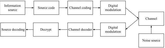
and access technologies. Digital communication refers to a communication method of transmitting messages in digital form or modulating carrier signals in digital form before transmission. The general model of a digital communication system is shown in Figure 1.
Fig. 1. General Model of Digital Communication System
The digital transmission system mainly designs ASK, PSK, FSK, QAM, MSK, OFDM and other technologies. Program-controlled switching, information transmission, communications networks, data communications, ISDN, and broadband IP technologies will all involve digital transmission technologies. Digital transmission systems can serve as a general basis for other communications and processing technologies.
3.2 Positioning technology in navigation
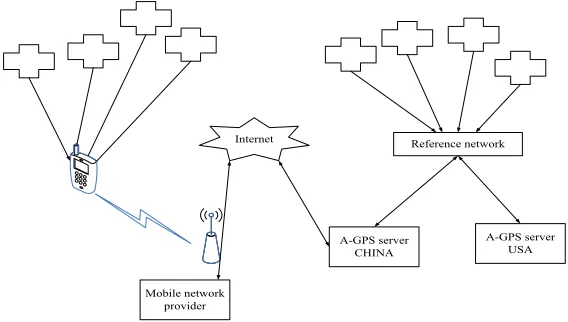
Vehicle positioning is the most critical function in the vehicle navigation system. If the location information of the current vehicle cannot be obtained, navigation will not be discussed at all. Global positioning system is a commonly used positioning technology. However, GPS positioning has many disadvantages such as large positioning error and long positioning time. In addition, even if the surrounding environment of the vehicle is complicated and the shelter is severe, the terminal may not even receive the satellite signal, and the positioning cannot be completed. In the research process of the project, the hybrid positioning technology based on it was adopted. This technology combines AGPS technology, mobile CELLID technology, and radio orientation technology to give more accurate vehicle position information and make up for many flaws in a single positioning technology. AGPS system consists of GPS positioning satellites, global satellite positioning system reference network, AGPS server, mobile communication network and AGPS terminal, as shown in Figure 2:
Information
source Source code Channel coding modulationDigital
Channel
Channel decoder Decrypt
Source decoding modulationDigital
Fig. 2. Block diagram of AGPS system
The global positioning system reference network has a number of observatories around the world. It is responsible for monitoring and recording all the GPS satellites' ephemeris data, Doppler frequency shifts, and other required positioning information over the entire area. This reference network is connected to the AGPS positioning server through a proprietary protocol, and the AGPS server periodically issues a request to dynamically refresh the stored GPS satellite database from the reference network. When the terminal needs to locate, its approximate location is reported to the AGPS server through the mobile communication network, and the server provides auxiliary information to the AGPS terminal through the mobile communication network, such as auxiliary information for calculating the position of the AGPS terminal and auxiliary information for measuring GPS pseudo range. Using this information, the terminal can quickly capture the satellite and receive measurement information, thereby calculating the current location of the AGPS terminal (terminal assisted positioning mode) or the position calculated by the server (network assisted positioning mode). In this way, the first positioning time can be greatly reduced to a few seconds. At the same time, the sensitivity of the AGPS terminal is related to the first positioning time TIFF and the number of code domain range segments to be searched. After using AGPS technology, the range of the code domain to be searched by the terminal is reduced, and it can be stored in a certain code domain for a longer period of time, thus increasing the sensitivity of the AGPS terminal.
3.3 Radio directional technology
The emergence of AGPS positioning technology has made up for many shortcomings of the global positioning system, but it still cannot solve the problem of indoor positioning. When the positioning system searches for zero satellites, only the prediction of the target position can be achieved, and the accuracy is between 500m-1500m. In order to overcome such situations, radio orientation sub-modules were independently developed during the research of the subject. When the approximate
Internet
Mobile network provider
A-GPS server
position of the terminal is determined, the use of the radio orientation module can further reduce the positioning range and achieve the purpose of precise positioning.
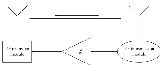
The radio directional system mainly relies on the transmission and reception of wireless radio frequency signals to transmit terminal information. The system includes a transmission module, a receiving module and a necessary power amplification module. Block diagram of radio directional system is shown in Figure 3.
Fig. 3. Block diagram of radio directional system
In Figure 3, the transmitting module is responsible for providing the specific identification information of the terminal and can modulate this identification information to the radio frequency band with a certain modulation method. The amplified RF signal is transmitted into the space via the antenna system. The identification information data format and the number of data bits here have terminal uniqueness and extensibility. In practice, the transmitting module will work in the broadcast mode, so its antenna system should have omnidirectional characteristics and should have higher gain. The receiving antenna system operates in directional mode with narrow main lobe width and high gain. The radio frequency signal received by the antenna system is first input to a receiving chip that also supports multiple modulation modes to perform demodulation, and terminal identification information is obtained therein. This information is sent into the processing unit together with the terminal position information at the antenna. According to the identification, the identity of the terminal is determined. In contrast to the reference direction, the direction of the terminal is determined.
RF receiving
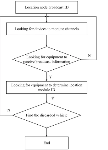
Fig. 4. Flow chart of radio directional system
The workflow of the entire radio direction system is shown in Figure 4. In the positioning terminal, the ADF7012 chip is used as the transmitting module, and the identification number ID of the positioning terminal is input to the chip. Once the system is started, the chip broadcasts the identification number ID of the owning terminal according to a certain period and a fixed power. Once the mobile device searching for personnel enters the coverage area of the RF signal transmitted by the chip, it will continuously monitor all the wireless channels. After receiving the signal sent by the directional module, the identification number ID can be determined through demodulation, the direction of the transmission source is determined by the directional antenna, and the search is completed.
3.4 The main technology of PRONAVI system
The PRONAVI system extracts the trajectory of the collected taxi passenger and matches it to a digital map. This process is called map registration and then a historical database is built. When carrying passengers, taxis have more specific destinations and more sensitive arrival time restrictions. When there is no passenger, the behavior of the taxi is very uncertain. Therefore, only the passenger data is used to build the database. The historical database contains data for a total of 9 months from January to March 2017 and October 2017 to March 2018. When establishing the history database for the travel time of each section, the statistical time interval needs to be determined. The PRONAVI system divides and adjusts 24h to the optimal statistical time interval using the description minimum length principle. For workdays
Location node broadcast ID
Looking for devices to monitor channels
Looking for equipment to receive broadcast information
Looking for equipment to determine location module ID
Find the discarded vehicle
End Y
Y
N
and rest days, the best statistical time interval is determined according to the principle of minimization (equal to the approximate error + model complexity) described in formula (1).
(1)
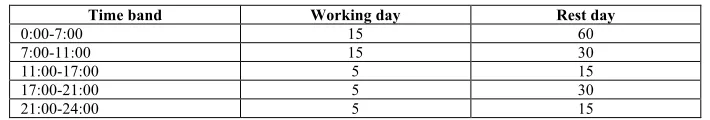
Table 1 lists the results. Most taxi rides take place between 10:00 and 24:00 daily. Therefore, more data reduces the variation in data observations. After 11:00, a shorter statistical interval is used. It should be noted that the traffic situation varies from 7:00 to 11:00 every day. The result in Table 1 is a long-time interval. This is not to say that the time interval of 15 minutes can meet the needs of observations of changes in traffic conditions. Relatively few observations must extend the statistical interval to obtain a sufficient number of samples and reduce the number of time periods in which the samples are missing. Optimal data statistics interval is shown in Table 1.
Table 1. Optimal data statistics interval
Time band Working day Rest day
0:00-7:00 15 60
7:00-11:00 15 30
11:00-17:00 5 15
17:00-21:00 5 30
21:00-24:00 5 15
4
Result Analysis and Discussion
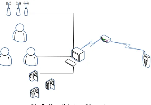
4.1 The overall design of multisource data hybrid communication system
Fig. 5. Overall design of the system
As can be seen from Figure 5, the following major tasks need to be done in the implementation of this topic: The first is the collection of multi-source data. The various sensor information, voice information, and image information are collected on a data hybrid terminal on the ship for unified storage and management. The second is a reasonable treatment of various types of data of different sizes. For the collected various types of data, it needs to be processed into a standard data stream. The third is to develop a reasonable set of data transmission solutions. After the collection of various types of data information is completed, the data must be processed and stored first. The urgency, real-time, accuracy, type, ship distance, and rate of information were specifically analyzed. Then, according to a predetermined rule, the corresponding best communication means is selected.
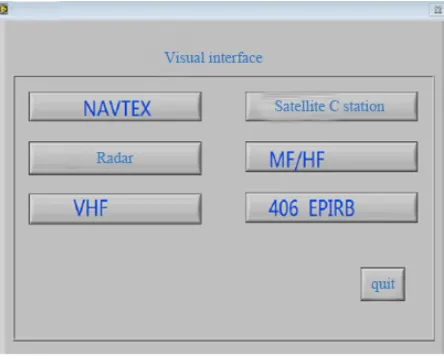
4.2 Display interface of multisource data hybrid communication system
display effect. The system structure of Figure 6 is a common medium and large ship connection.
Fig. 6. Connection mode of ship
The visual interface is the object directly touched by the ship's driver. Its design and operation are directly related to the use effect of the system. Using LabVIEW as a display method, the display content is planned for each module function. In general, radar image information and status information of various navigation devices are planned as an interface. When the chart information is to be displayed, the system switches to another display interface. The display system is convenient and quick to switch display or to deal with replacement display, as shown in Figure 7.
X-Band RADAR
GPS
AIS
Magnetic compass
S-Band RADAR
Display
Display
Display
Display CONNING
ECDIS Four
way serial
This interface only collects menus that focus on common functional devices. The advantage of this menu is the simplicity of the interface. It can directly find the target device. The disadvantage is that the interface is not fully utilized, many information is included, and switching between devices is required.
Taking into account the importance of electronic charts, electronic charts are included separately under the navigational warning framework. The electronic chart information display system can not only provide environmental information around the current location, but also plan routes to prevent deviations. It is also an important display platform that can receive and process navigation device information in the access system network. Electronic charts can be used as bottom-level images. The targets tracked by radar, AIS, and other devices are plotted on the upper layer. This is an advantageous combination of information on the environment, routes, target obstacles and so on. It is very clear for the driver to make decisions. When the electronic chart information needs to be displayed, the entire screen can also be switched.
4.3 Judgement of road conditions based on floating cars
Advanced path navigation is an effective means to facilitate people's travel and reduce traffic congestion and eventually achieve high-quality mobile network location services. Real-time acquisition of dynamic traffic status information is the basis for high quality path navigation planning. The real-time dynamic acquisition and processing of road traffic flow status information is a prerequisite for reliable assessment of the traffic conditions of the corresponding road sections. Traditionally, roadside stationary traffic detection equipment is mostly used to obtain road traffic status information. Ring coil sensors, remote sensing microwave sensors, and video-based detection devices are the most common technologies. These devices have problems such as high costs, serious losses, and poor maintenance. At present, more advanced traffic information collection methods are floating car data collection technologies.
Fig. 8. Structure diagram of floating car system
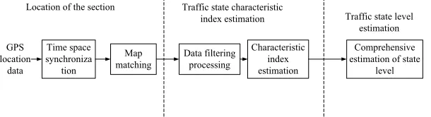
As shown in Figure 8, the floating car system is mainly composed of three parts, which are an on-vehicle device, a mobile communication network, and a traffic information processing unit. In actual work, the floating car positioning module collects and processes GPS positioning data in real time to generate road traffic flow basic feature information, such as vehicle number, time stamp, position coordinates, instantaneous speed, etc. It is synchronized in time and space. Through the map, the sections of the floating car are matched. On this basis, traffic flow status indicators such as the average speed, travel time, and congestion index of the road section are calculated. Finally, based on various index parameters, data fusion and modeling analysis methods are used to comprehensively evaluate the road traffic status level. The process flow of floating car data is shown in Figure 9.
Fig. 9. The process flow of floating car data
The data acquisition and processing technology of the floating vehicle integrates the resources of the assisted GPS satellite positioning system and the mobile communication system. It can collect the dynamic characteristics of road traffic flow and its changes from time to space in a more accurate, real-time and comprehensive manner. At present, relevant personnel of the project team are doing related research. By applying it to smart navigation systems, the navigation function is more complete
Floating car Traffic information
processing center GPS reference
receiver
Base station GPS satellite
Time space synchroniza
tion
Map
matching Data filtering processing
Characteristic index estimation
Comprehensive estimation of state
level GPS
location data
Location of the section Traffic state characteristic
index estimation Traffic state level
the difference between left and right turn times and straight-through vehicles. The system calculates the time cost of left and right transfer travel time for different combinations of traffic trunks and branch roads on weekdays and rest days, as shown in Figure 10. By considering the time cost of left and right travel, the Dijkstra method is used to retrieve the best path using the travel time cost of the combination of the inflow road section and the outbound road section. The results include the shortest path, the shortest path that must use the highway, and the shortest path that does not use the highway.
Fig. 10. Left and right travel time cost
PRONAVI is compared with the other five navigation systems on the market. The validity of the multi-source data fusion database and the cost of the left and right travel time was examined. In the experiment, six vehicles were used to load other navigation systems. For the same starting point, each vehicle simultaneously searches for a route and travels, and follows the route search results of the respective navigation devices to the destination. Through the analysis of the experimental data, the prediction errors of PRONAAVI using the historical database, left-right travel time cost, and real-time information such as JARTIC are minimized. Without the cost of left and right travel time, the absolute prediction error will increase significantly. The path search results of PRONAVI are diverse. Experiments have shown that the historical database and the time left and right travel time costs already contain daily crowding information. At the same time, the integration of real-time information such as JARTIC and rainfall can effectively improve the system's adaptability to different traffic and environmental conditions, thereby improving the accuracy of travel time prediction.
0 5 10 15 20
21:00
17:00 13:00
5:00
Left
a
nd
ri
gh
t t
ra
vel t
ime
cost
/s
5
Conclusion
With the rapid development of science and technology and the increase of marine transportation business, ship and automobile communications include analog voice, fax, business data, video images and other types of business. The communication facilities and information types between ship and ship shore are not uniform. This brings about various problems such as cumbersome operation, low terminal intelligence, and high communication costs. There is an urgent need for a unified communications platform to process and transmit multi-source data.
A ship data hybrid transmission system based on embedded technology was designed and implemented. The system can capture and store the types of information commonly used on ships (including sensor information, voice information, picture information, etc.). At the same time, these different types of data are mixed and processed. Then, the unified data stream is transmitted to the modulated transmission system. In addition, according to the actual situation, PRONAVI technology was introduced. Based on the Mesh structure, the PRONAVI network was built, which is in line with the theme of future cyber security and intelligence. It can better meet future business and network development needs.
6
References
[1] Vieira, M. A., Vieira, M., Silva, V., Louro, P., & Barata, M. (2015). Error control on spectral data of four‐wave mixing based on a‐sic technology. Physica Status Solidi, 12(1-2): 181-186 https://doi.org/10.1002/pssc.201400067
[2] Chen, K. C., & Lien, S. Y. (2014). Machine-to-machine communications: technologies and challenges. Ad Hoc Networks, 18(3): 3-23 https://doi.org/10.1016/j.adhoc.2013.03.007 [3] Meschut, G., Hahn, O., Teutenberg, D., & Ernstberger, L. (2015). Influence of the dosing
and mixing technology on the property profile of two-component adhesives. Welding in the World, 59(1): 91-96 https://doi.org/10.1007/s40194-014-0182-3
[4] Xiong, Y., Lin, J., & Qin, W. W. (2014). Research on multi-source data tourism application platform in the minority area's scenic spot. Open Cybernetics & Systemics Journal, 8(1): 553-559 https://doi.org/10.2174/1874110X01408010553
[5] Feng, X., Li, C. Y., Chen, D. X., & Tang, J. (2017). A method for defensing against multi-source sybil attacks in vanet. Peer-to-Peer Networking and Applications, 10(2): 305-314 https://doi.org/10.1007/s12083-016-0431-x
[6] Shaikh, M. (2017). Mutability and becoming: materializing of public sector adoption of open source software. Ifip Advances in Information & Communication Technology, 389: 123-140 https://doi.org/10.1007/978-3-642-35142-6_9
7
Author
Jinzhu Xiong is a Researcher of School of Automotive and Electromechanical Engineering, Xinyang Vocational Technical College, HeNan, China. His research interests include Multi-source Data Hybrid Technology.