Interactive Head Control of Embroidery Machine using
Embedded Web Server
https://doi.org/10.3991/ijoe.v13i04.6848
Hiren K Mewada
Charotar University of Science and Technology, Gujarat, India
Abstract—This paper proposes the design and implementation of prototype model to control embroidery machine using single board ARM processor. Wil-com is the software largely used for embroidery design. Designs prepared using Wilcom software are printed and supplied to the machine for further process. The proposed prototype model extracts the design data from this software by avoiding the printing and/or scanning of the user design and the design data are supplied to ARM based prototype embroidery machine for printing. In proposed model, the pencil is used as printing head and A4 size paper is used for the printing. Further to control the head, Use of web server design is also proposed using ARM processor.
Keywords— Wilcom software, Embroidery machine, ARM Processor, embed-ded web server
1
Introduction
This paper proposes the concept of single board computer based embedded web server design for embroidery machine control application. General web server are developed using general-purpose computer such as NT server or UNIX/Linux work-station. This web server requires large memory, fast processing multi-tasking operat-ing system with other resources. In contrast, embedded web server is designed usoperat-ing embedded system with support of internet software suit as well as application code to monitor and control the system. It is system which monitors and calibrates the sensors and devices using web pages through fast Ethernet communication media. In this paper, use of embedded web server to control embroidery machine using ARM pro-cessor is proposed with implementation of prototype model.
graph plotter, where the pantograph moves the frame product to the defined coordi-nates of the design expressed by the design. The coordicoordi-nates are defined based on the grids in terms of x-coordinate and y-coordinate. The embroidery machine reads these coordinates from the design to move the pantograph into the position of needle. This paper demonstrates the prototype model, where pantograph is fixed and embroidery head moves to the position defined by the coordinates from design data.
Wilcom is the software used in the textile industry to create embroidery design. It allows the designer to create, edit and output embroidery design with ease. Two methods are used to supply the design data to computer controlled embroidery ma-chine. In first method, the design exists in printed document. This design is scanned and digitized to obtain the coordinates. Design may be enlarged according to the re-quirement. Alternative method is use of software supporting online drawing.In both methods, the coordinates obtained from the design are saved into internal memory of software with "emb" filenames (filenames ending with .emb). However the process is complicated because the format specified by the software is not understandable by the embroidery machines i.e. they have different file name ending. Therefore it is re-quired to process the software file such that embroidery machine can read and under-stand. The conversion process is explained in the section 3. As textile industries are growing industries with up gradation in technology, the need arises for to control multiple machines using embedded web server. The following section 2 discusses the design of embedded web server using single computer and their applications. In sec-tion 3, the implementasec-tion of prototype model of Embroidery machine using ARM processor is presented. In last section 4, results are discussed summarized with future scope.
2
Literature Surveys
Embroidery designs are widely used on clothing and in textile industries. Wilcom is the most popular software to prepare embroidery design. These designs are supplied to the machine in a specific language where machine interprets these data to control its needle (i.e. head) to print on clothing [1]. This is vital steps for the operator of the embroidery machine. Therefore, this paper proposes an implementation which con-verts the design files which can be interpreted by the machine.
web server were presented in [7]. This web server can provide the remote monitoring and controlling of real time information at the user desk. They utilized ARM7 based microprocessor to develop web server. RTL8019AS Ethernet control chip is used for the data access over internet. By analyzing the various surveys, it is found that either improvement in controlling of embroidery machine is proposed or web server design for other application has been proposed. Presently, the controlling of embroidery machine remotely using embedded web server is basic requirement as it allows con-trolling multiple machine simultaneously. Therefore this paper proposed conceptual representation of embedded web server design for this machine and implementation of prototype model for the embroidery machine. Overall contribution in the paper is as follows:
1. Conceptual representation of embedded web server design to control em-broidery machine
2. The Wilcom software interface to the ARM processor to control the proces-sor based on information obtained from this software.
3. Display of the captured design from Wilcom software to the touch screen LCD for the verification.
3
Implementation of Prototype Model
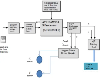
To implement prototype model of embroidery machine with embedded web server, the ARM processor based single board computer i.e. AT91SAM9G45 is utilized. Further features of AT91SAM9G45 can be obtained from the company website [3]. The ARM processor SAM9G45 allows integration of multiple communication inter-faces and it also provides a resistive touch screen controller. This touch screen is utilized to display the design read from the Wilcom software and also to draw design by the user. The design drawn on touch screen is utilized by the embroidery head to stitch. The key functionality of the embroidery machine is displacement of head. This displacement in x- and y- direction is obtained by the stepper motor which is con-trolled by the ARM SAM9G45 processor. Overall block diagram is shown in figure 1, where the design is obtained from the Wilcom software. The coordinates of displace-ment are obtained from the emb file. Using these coordinates, the ARM processor controls the displacement of stepper motor and in turn the displacement of embroi-dery head.
Fig. 1. Block diagram for prototype model of Embroidery machine control using ARM Proces-sor
The design file received at the SBC board is converted to byte array to get each hex data in separate form. Array of the data consists of functions, X-displacement and displacement consecutively. Only two information among these i.e. X- and Y-displacements are needed to control the placement of embroidery head. In Wilcom software generated file, there are positive and negative displacements in both X- and Y-directions of 2D Plan. The separation of these coordinates is required to control the stepper motor which moves the embroidery head to X and/or Y-direction. For the user interaction, the LCD touch screen is also interfaced where the design obtained from the Wilcom software is also displayed on this LCD screen. Thus in the proposed algo-rithm, the ARM processor has been programmed to perform dual task simultaneously. To make process fast for displacement of embroidery head and to display the design on LCD screen, the five stage pipelining and flexible task scheduling algorithm is proposed in the design.
3.1 Software Architecture
The web page for the embedded server is designed in software using QT embedded tool and it is interfaced with the ARM processor to control the displacement of em-broidery head. The supply the emem-broidery design, two alternatives is implemented in this prototype model. User can input the embroidery design using Wilcom software which generates corresponding emb file. In the proposed design, a touch screen LCD is also interfaced which performs dual task i.e.to display the design from the Wilcom software and to allow drawing on that screen. To display the design on LCD screen, the emb file is decoded and scaled down. The painting tool of QT Embedded tool is used to display it on LCD screen. Thus coordinates extracted from emb file are used simultaneously by the QT embedded tool to display on LCD screen and by the ARM processor to control the head displacement.
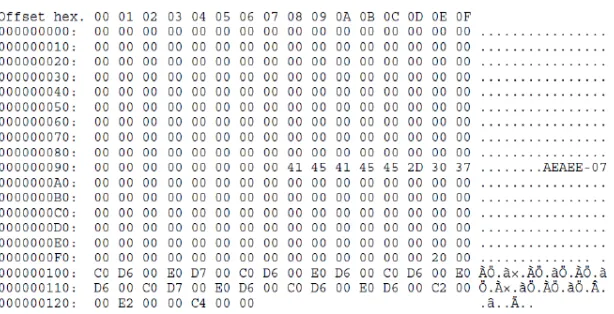
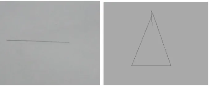
The simplest embroidery design is the design consists of either horizontal or verti-cal line. Therefore for the demonstration of implementation of prototype model, here horizontal line, vertical line and triangle design is utilized as a designer input. This design which is drawn using Wilcom or touch LCD screen is utilized by the embed-ded processor to get corresponding displacement of embedembed-ded head. These displace-ment coordinates are extracted from the emb file.The structure of this emb file gener-ated by the Wilcom software for the horizontal line is shown in figure 2.
Fig. 2. ‘emb’ file generated by the Wilcom to get coordinates for the horizontal line
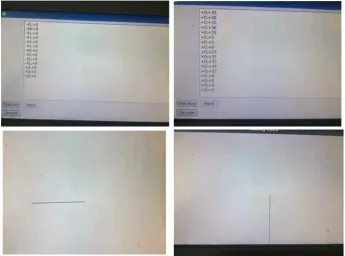
and move are used considering central pixel location as an origin of the design. The simulation results for the simplest design of horizontal and vertical lines are presented in Figure 3 where single displacement in either X- or Y- direction is required. Similar-ly, for complex design i.e. triangle design needs displacement in both directions sim-ultaneously which is challenging and basic requirement for any complex design. The simulation result for the triangle is demonstrated in Figure 4.
Fig. 3. Data generated from Wilcom’s emb file for the horizontal and vertical line and corre-sponding display on LCD screen
3.2 System hardware design
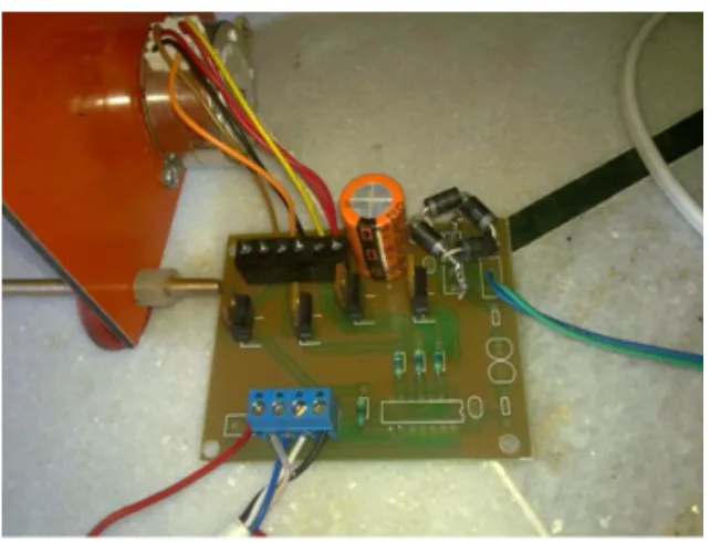
To demonstrate the hardware based controlling of embroidery head, here pencil is used as an embroidery head in prototype model. The displacement of head is con-trolled by the two stepper motors which in concon-trolled by the ARM processor SAM9G45. The screen shot of mechanical hardware used in industry based on nut-bolt mechanism for the X- displacement is shown in figure 5. Similarly for Y-displacement circular to linear conversion process is used.
Fig. 5. Model of nut-bolt mechanism for the X-displacement used in industry
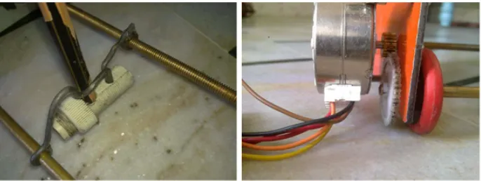
As the stepper motor rotates the screw clockwise or anticlockwise, then nut slides left to right or right to left. The head (i.e. pencil in the proposed design)is connected with the nut in the design.Similar design has been proposed in the prototype model by using solid pipe of metal and patterned the screw with 3-16-18 sized die. Same way nut is designed with same sized tub to match the nut-bolt mechanism. This proposed design is shown in figure 6(a). To obtain Y displacement, the circular motion is con-verted in linear motion by means of robotics tire mechanism as shown in below figure 6(b).
Fig. 6. (a) Nut-bolt mechanism for the X-displacement (b) circular to linear mechanism for the Y-displacement
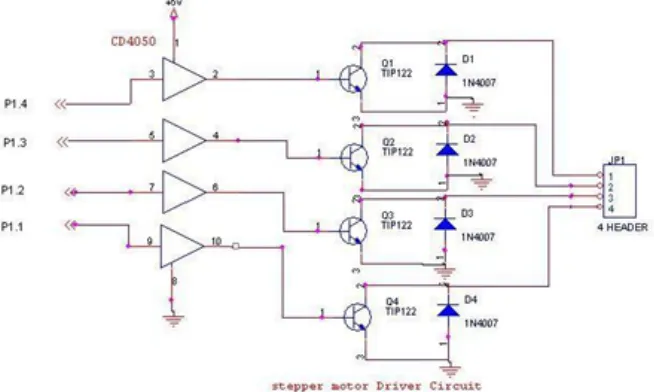
model, bipolar permanent magnet stepper motors are used. The displacements are either positive or negative from current position of the stitch; hence corresponding pulses are given to the motor to rotate either in clock wise or anticlockwise direction. The pulses to the stepper motor are transmitted by processor general purpose in-put/output (GPIO).The SBC-SAM9G45 has a 2 x 5Pin 2.54mm spaced GPIO inter-face, i.e. J1 [3]. Further specification can be obtained from the reference Guide avail-able in [3]. From the 10 pins, first eight pins are interfaced to stepper motor i.e. PA25 to PA28 are interfaced to stepper motor providing X-displacement and PA29 to PA31 and PA27_ADC are interfaced to the stepper motor providing Y-displacement. Thus four bit pattern coding is used to control the both motors. The driving circuit for the stepper motor using TIP122 driver circuit is shown in figure 7 where the TIP122 is a switching transistor with high power capabilities and can drive the stepper motors with high torque up 5Kgcm [4]. TIP122 driver circuit provides faster response in case of weak signal from the processor to pulse the motor is selected in comparison to other available driver circuit i.e. ULN2003 [5].
Fig. 7. Stepper motor driver circuit using TIP122
Here the most important task is sync between X and Y displacement when design has both the displacement simultaneously. For this the pulses should be transmitted to the stepper motors such that design is drawn with minimum error. To get the clock-wise and anti clockclock-wise rotation with high torque stepping two coins of motor are turn ON at the same time using following logical data are required from the GPIO pins.
Clockwise rotation: CH-9H-3H-6H Anti- clockwise rotation: 6H-3H-9H-CH
Table 1. Pulse sequence to be to stepper motor
Pulse Coil a1 Coil b1 Coil a2 Coil b2
1 ON ON
2 ON ON
3 ON ON
4 ON ON
Based on the data taken from design file the above sequence of pulses needs to be applied or repeated as required. The stepper motor is working on 24V operating po-tential. And hence an extra supply needs to be provided to driver circuitry. Because the SAM9G45 board output is only 3.3V which is not sufficient to drive the motor. Before doing so, we tested the GPIO by sending the bit pattern manually. The actual circuit design is shown in Figure 8. As the logical signal is supplied from the SBC’s GPIO pins which do not required clipping operation, the diodes 1N4007 at other side are omitted in the proposed design which was suggested in the circuit shown in figure 7.
Fig. 8. Stepper motor driver circuit in the proposed prototype model
Fig. 9. Practical results obtained on A4 size paper with head control for different pattern drawn in Wilcom software (a) Horizontal line (b) Triangle pattern
4
Conclusion and Future Work
This paper proposed the concept of embedded web server design using ARM based single board computer. An embedded web server design needs a GUI implementation for the user interface and controlling of several applications from that GUI. The sup-portive futures of SAM9G45 ARM processor with QT enabled software makes it suitable choice for such web server design applications. Using this concept, this paper proposed the controlling of Embroidery machines using GUI design. Use of Wilcom software is proposed as a GUI. The prototype model of embroidery machine has been implemented and Wilcom software based controlling of this machine is presented in the paper. LCD is also interfaced to see the embroidery design drawn in Wilcom software. In the proposed model, single embroidery head has been controlled to draw the design hence only single color thread can be controlled according to the user’s design. The model can be extended where multiple embroidery heads can be con-trolled or multiple embroidery machines can be concon-trolled based on use selection in Wilcom software. The hardware can also be interfaced with other devices through fast Ethernet using master-slave concept. With the tremendous capability of this SBC board in GUI, this system will provide easy and fast data acquisition and remote login when connected with the internetwork.
5
References
[1]Wilcom Sofware “https://www.wilcom.com/”
[3]ARM Processor AT91SAM9G45 specification, Core Wind Technology Co. Limited. Hong Kong, http://www.armdevs.com (Last accessed on July 2016).
[4]Stepper motor driving circuit using TIP122, http://www.embed4u.com/stepper-motor-drive-using-microcontroller/
[5]Stepper motor driving circuit using ULN2003,
http://www.elecrow.com/wiki/index.php?title=ULN2003_Stepper_Motor_Driver
[6]Changhua Lu, Xiaofei Zhang and Qingrong Sun (2010), Design of an embedded embroi-dery machine controller based on dual processors, 2nd International Conference on Ad-vanced Computer Control, Shenyang, pp. 168-171.
[7]Jianming Liu, Yunjie Zhang, Lili Xu, Jincai Wang (2013), Design and Implementation of Embedded Web Server in Industrial Control Systems, International Journal of Communi-cation and Network, Vol. 5, pp. 65-68. https://doi.org/10.1109/JCN.2003.6596680
[8]Guanghui Xu, Yongbo Huang, Jun Deng and Taiyang Xu (2013), Design and Implementa-tion of the Numerical Control Multi-Needle Quilting Embroidery Machine, Communica-tions in Information Science and Management Engineering, Vol. 3(7), PP.310-314. [9]C. Lu, M. Tian and W. Wang (2009), Design and Implementation of a Computerized
Em-broidery Machine's Controller Based on ARM and DSP, International Workshop on Intel-ligent Systems and Applications, Wuhan, pp. 1-4.
[10]Y. Y. Li, G. Z. Cao, H. Qiu, J. F. Pan and C. C. Yang (2011), Development of embroidery machine vector control speed regulation system based on DSP, 4th International Confer-ence on Power Electronics Systems and Applications, Hong Kong , pp. 1-5.
[11]Feng Lu, Shihua Gong, Xiqian Guand and Pingjiang Wang (2012), Research on the High-speed Sewing Control Technology for the Electronic Pattern Sewing Machine, 2nd Inter-national Conference on Computer Application and System Modelling, Atlantis Press, Par-is, France pp. 1030 – 1032.
6
Author
Hiren K Mewada is with Charotar University of Science and Technology,
Guja-rat, India ([email protected])