Http://www.ijetmr.com©International Journal of Engineering Technologies and Management Research [21]
PRACTICAL STUDY TO IMPROVEMENT THE PERFORMANCE OF
HEAT EXCHANGER USING PASSIVE TECHNIQUES
Farah Abdulzahra Taher *1, Dr. Zena Khalefa Kadhim 2
*1, 2 Mechanical Engineering Department, University of Wasit, Iraq
Abstract:
The aim of this study to improve the performance of heat exchanger by using the medium integral fins on the cross flow heat exchanger practically, so, two the heat exchangers from copper were manufactures with eight passes for comparison under different boundary conditions. The water flow rate flow inner the tubes with (2, 3, 4, 5, 6) L/min with inlet temperatures (50, 60, 70) oC, as for the air flow rate were passed outer the tubes by speeds (1, 1.7, 2.3) m/sec. The results show that the medium integral finned tube gives more improvement the heat transfer than the smooth tube about 203.97% and 205.1% was enhancement factor. Motivation: The aim is improvement the heat transfer coefficient for cross flow heat exchanger by using medium integral finned tube. Study the effect of various water stream rate, air speed and inlet water temperature on heat transfer coefficient for them, Finding the cases which enhanced heat transfer for various ranges of air and water as well as inlet temperatures and the speed at the entrance. Develop the empirical correlations for (Nua) of smooth and medium integral finned tubes as function of (Pra) and (Rea).
Keywords: Heat Transfer; Improvement the Performance; Medium Integral Finned Tubes; Cross Flow Heat Exchangers; Reynolds Number; Heat Transfer Coefficient.
Cite This Article: Farah Abdulzahra Taher, and Dr. Zena Khalefa Kadhim. (2019). “PRACTICAL STUDY TO IMPROVEMENT THE PERFORMANCE OF HEAT EXCHANGER USING PASSIVE TECHNIQUES.” International Journal of Engineering Technologies and Management Research, 6(8), 21-33. DOI: https://doi.org/10.29121/ijetmr.v6.i8.2019.437.
1. Introduction
DOI: 10.5281/zenodo.3370525
Http://www.ijetmr.com©International Journal of Engineering Technologies and Management Research [22] et. al. (2019) [4], 3D experimental and CFD study to the cross flow heat exchangers, employing the fluids of working (water, oil and with nanofluid SiO2) with the vary concentration Nano fluid
and their influence on the heat transfer coefficient. The outcomes appeared that heat transfer and heat transfer coefficient were higher in the tube with low fins than the smooth tube. The growing was 72.05% for oil and 104.1% for water in the finned tube. Farah and Zena (2019) [5], a practical study of the effect of fins on improving the heat transfer of a cross flow heat exchanger with integrated fins 6.2 mm height. The air flows from the outside at a speed of (1, 1.7 and 2.3) m/s. The hot water flows inside it (2, 3, 4, 5, 6) L / min with inlet temperatures of (50, 60, 70). The effect of these variables on heat transfer and optimization were the high integral finned tube the best in heat transfer about (329.9%) and the improvement factor (291%). Chen et. al. (2014) [6], the qualities of the heat transfer and pressure drop in finned tube banks through a trial open high-temperature wind. The impacts of the dimensions of the fins (width , height , pitch) and air speeds (6, 8, 10, 12 and 15) m/s on fin efficiency as well as the convective heat transfer coefficient. The result show that as the air speed, fin height and fin width increment, fin efficiency diminishes. Convective heat transfer coefficient is corresponding to fin pitch, yet conversely relative to fin height and fin width. The heat transfer limit is identified with fin efficiency, convective heat transfer coefficient and finned proportion. Pressure drop increments with the increasing the fin height and width. The relationships of the fin efficiency, Nusselt's number and Euler Number are produced in light of the empirical information. Kumar et. al. (2005) [7], an exploratory examination has been done to the condensation of R-134 vapors more than five single horizontal round integral fin tubes of 472 fpm, 417 mm length and diverse fin heights of 0.45, 1.14, 1.47, 1.92 and 2.40 mm. The roundabout fins are rectangular in style and the fin thickness of all tubes is 0.70 mm. The tube with the fin height of 0.45 mm has given the most maximum improvement factor (EF), of the request of 3.18 in compare with that anticipated by the Nusselt's demonstrate for a plain tube. Ayad Mezher et. al. (2011) [8], Examine the heat transfer qualities for cross stream air cooled single aluminum tube multi passes (smooth and integral low finned tube) and the impact of the indispensable low fins (trapezoidal or rectangular ) in upgrade the heat and concentrate all factors which have impact on heat transfer phenomena. The speeds of air over the test area are (1, 2 and 3) m/sec, the water stream rate is (5l/min) and the temperatures of the entry water to the test tube are (50, 60, 70, 80) o C. The main test area has a smooth aluminum tube of eight corridors with internal diameter 17mm and external distance across 19mm.The second test segment has an essential low finned aluminum tube of eight corridors with internal diameter 17mm, root diameter 19mm and external diameter at the tip of fin 22 mm. The corridor has a length 251mm inside the conduit with 125 fins. The fin's height is 1.5 mm with a thickness of 1mm and pitch 2mm. The test show that the air side heat transfer coefficient of the smooth tube was lower than that of the low finned tube and the improvement proportion or (Nuaf /Nuas) was (1.86 to 2.38) for eight passes. The experimental connections for the air side spoke to by Nusselt's number. The heat load of the low finned tube is higher than that of the smooth tube, by (1.8 to 2.13) times. Enhance of the outside heat transfer coefficient by increasing the air speed.
2. Materials and Methods
2.1.Theoretical Equations
Http://www.ijetmr.com©International Journal of Engineering Technologies and Management Research [23] 𝑄 = 𝑚𝑤̇ 𝐶𝑝ℎ(𝑡ℎ1− 𝑡ℎ2) = 𝑚𝑎̇ 𝐶𝑝𝑐(𝑡𝑐2− 𝑇𝑐1) 1
𝑄 = 𝑈𝐴𝜃𝑚 2
The overall heat transfer coefficient
𝑈 = 1 ℎ𝑜+
1 𝐾+
1
ℎ𝑖 3
Log mean temperature difference (LMTD)
𝐿𝑀𝑇𝐷 = 𝜃1−𝜃2 ln(𝜃1
𝜃2
⁄ ) 4
Calculations heat transfer coefficient for smooth tube, [10]
For smooth tube
ℎ𝑜 = 1
1
𝑈𝑜 −
𝑑𝑜 𝑙𝑛(𝑑𝑜⁄ )𝑑𝑖
2𝑘 −
𝑑𝑜 ℎ𝑖𝑑𝑖
5
For integral finned tubes
𝐴𝑜𝑓 = 𝐴𝑜𝑠 = 𝜋 𝑑𝑜𝐿 , Clean surfaces, [11, 12]. From eq. (3) we get ho
ℎ𝑜 = 1
1
𝑈𝑖 −
𝑑𝑖 𝑙𝑛(𝑑𝑟⁄ )𝑑𝑖
2𝐾 −
1 ℎ𝑖
6
Reynolds number, Prandtle number and Nusselt's number for air side:
𝑅𝑒𝑎 = 𝑈𝑎𝑖𝑟𝑑ℎ
𝑣𝑎 7
𝑃𝑟𝑎 = 𝜇𝑎𝐶𝑝𝑎
𝛫𝑎 8
𝑁𝑢𝑎 = ℎ𝑜𝑑𝑜
𝛫𝑎 9
Reynolds number, Prandtle number and Nusselt’s number for water
𝑅𝑒𝑤 = 𝑢𝑤 𝑑𝑖
𝑣𝑤 10
𝑃𝑟𝑤 = 𝜇𝑤𝐶𝑝𝑤
DOI: 10.5281/zenodo.3370525
Http://www.ijetmr.com©International Journal of Engineering Technologies and Management Research [24] 𝑁𝑢𝑤 =
ℎ𝑖 ×𝑑𝑖
𝐾𝑤 12
To turbulent flow by Dittus and Boelter, [13]:
𝑁𝑢𝑤 = 0.023𝑅𝑒𝑤0.8𝑃𝑟𝑤𝑛 13
(0.6 <Pr<100)
The actual heat transfer for the counter flow exchanger can be calculated from equ.1
𝑄𝑚𝑎𝑥 = 𝐶𝑚𝑖𝑛(𝑡ℎ1− 𝑡𝑐1) 14
For cross flowCmax mixed and Cmin unmixed or vice versa
𝜀 = (1
𝐶) {1 − exp[−𝐶(1 − 𝑒
−NTU)]} 15
𝜀 = 1 − exp {− (1
𝐶) [1 − 𝑒𝑥𝑝 − (NTU ∗ 𝐶)]} 16
Where, the heat capacity ratio is,
𝐶 = 𝐶𝑚𝑖𝑛 𝐶𝑚𝑎𝑥
The number of transfer units (NTU)
NTU =𝑈𝑜∗𝐴𝑜𝑠
𝐶𝑚𝑖𝑛 17
Enhancement factor:[14]
𝐸. 𝐹 % = ℎ𝑜,𝑓𝑖𝑛− ℎ𝑜,𝑠𝑚𝑜𝑜𝑡ℎ
ℎ𝑜,𝑠𝑚𝑜𝑜𝑡ℎ × 100 18
2.2.Experimental Apparatus
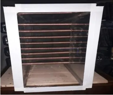
A laboratory device involved design and manufacturing the laboratory apparatus and test models, which consist of a test section made of Pyrex glass with dimensions (250×500×1200) mm. The test tubes with a length of 2 meters, description of the smooth and medium integral finned tube with 384fpm shown in table (1). The copper tubes that were joined by arrangement eight passes, the one passes are gone by horizontally through the test section with length (250) mm. The distance from slots center to other slots center (55mm) and diameter is equal to (24mm). Schematic diagram for laboratory device in figure (1), while the medium integral finned tube was shown in figure (2).
Http://www.ijetmr.com©International Journal of Engineering Technologies and Management Research [25] supply unit in this unit is passed the cold air through the following parts the centrifugal blower, the diffuser from galvanized steel and the air duct. Measuring devices are utilized to take readings from the laboratory apparatus hot-wire anemometer, Thermometer, flow meter, the pressure meter recorder model (ps-9302) with the rang (1-400) bar and thermometer type (tm-947sd), involve four channel with the thermocouple type (k) (-100 to 1300) °C is utilized to measure the temperature of entry and exit for water and air. Thermal imager utilizes to measure the surface temperature of the test tubes.
Table 1: Description of the copper tubes Tubes di do dr Hf Tf Tw Sf Ao/Ai
Smooth 19 24 - - - 2.5 - 1.263
MIF 19 28.5 21 3.75 1 1 1.6 5.0
2.3.Calculate Error in Experimental Readings
When taking experimental readings from the laboratory apparatus, there is an error rate that comes from the accuracy of the work of the measuring instruments and to achieve the accuracy required for the measured parameters, the experimental measured repeated times three or more in order to find the uncertainty error by using the method of Klein,[15].Calculation error were overall heat transfer coefficient (2.27 to -2.38)%, heat transfer (11.65-15.19)%, air side Reynolds number (0.174-0.17)%, air side heat transfer coefficient (2.95-3.14)% and (Nua) ( 3.027 to-3.223)%.
3. Results and Discussions
Figure (3) offer the relation between the (hi) with volumetric flow rates at inlet water temperatures and air velocity various for smooth tube and medium integral finned tube. (hi) was increased with increasing the temperature of the water entering and volumetric flow rate for water at the same air speed as a result of higher disturbance for water.
Figure 2: Photos of the medium integral
DOI: 10.5281/zenodo.3370525
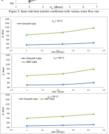
Http://www.ijetmr.com©International Journal of Engineering Technologies and Management Research [26] Figure 3: Inner side heat transfer coefficient with various water flow rate
Figure 4: The heat transfer rate with the air speed and various inlet water temperatures for two models 700 1200 1700 2200 2700
1 2 3 4 5 6 7
hi ( W/ m 2. oC )
Vw (L/min)
th1= 70 oC th1= 60 oC th1= 50 oC
Smooth tube th1=70oC
th1=60oC
100 300 500 700 900 1100 1300 1500
0.7 1 1.3 1.6 1.9 2.2 2.5
Q
Wa
tt
Uair (m/sec) th1= 70 oC Smooth tube 100 300 500 700 900 1100 1300 1500
0.7 1 1.3 1.6 1.9 2.2 2.5
Q
Wa
tt
Uair m/sec th1= 60 oC Smooth tube MIF tube 100 300 500 700 900 1100 1300 1500
0.7 1 1.3 1.6 1.9 2.2 2.5
Q
Wa
tt
Uair (m/sec) th1= 50 oC
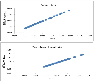
Http://www.ijetmr.com©International Journal of Engineering Technologies and Management Research [27] Figure (4) clear the relation between the heat transfer rate with inlet water temperature and air velocity for the two heat exchangers (Smooth and Med). The heat transfer rate was observed its increases with increasing the temperature of the water entering and air velocity due to high cold air speed occurred higher disturbance outside the tubes that increases the water side temperature difference (∆th), led to rises the surface temperature and the heat capacity of water within a little value. Figures (5) carried out the effectiveness of heat exchangers with (NTU), for two cases, the effectiveness (ε) was increased with increasing the number of the transfer units (NTU), that increasing due to rise air side overall heat transfer coefficient (Uo).
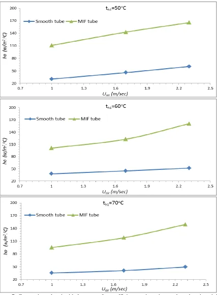
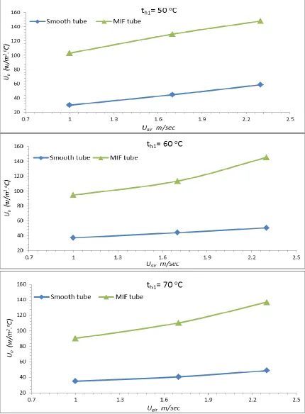
Figures (6), explain that the air side temperature difference (∆tc) with air speeds and (𝑡ℎ1). (∆tc) decreased with increasing air speed at the same inlet water temperature and increased with increasing inlet temperature water, due to higher heat transfer rate. Figure (7) show the effect of the different air speed and inlet water temperatures on the (ho) for two test models. The values of (ho) increase with air speed at the same inlet temperature water as a result of increasing the (Rea). Figure (8) show comparison of the (Uo) versus the various velocities (Uair). The (Uo) increases with increasing air velocity at constant inlet temperature for all models which examined, and to increasing the surface area as result as rise of high fins works to regulate the flow direction and the turbulence of air flow.
DOI: 10.5281/zenodo.3370525
Http://www.ijetmr.com©International Journal of Engineering Technologies and Management Research [28] Figure 6: Air side temperature difference with air speed for various inlet water temperature
3.1.Comparison These Results for Heat Exchangers with Study Farah And Zena [5]
Http://www.ijetmr.com©International Journal of Engineering Technologies and Management Research [29] Figure 7: Comparison the air side heat transfer coefficient against air speeds and various inlet
DOI: 10.5281/zenodo.3370525
Http://www.ijetmr.com©International Journal of Engineering Technologies and Management Research [30] Figure 8: The air side overall heat transfer coefficient with air velocities and various inlet water
Http://www.ijetmr.com©International Journal of Engineering Technologies and Management Research [31] Figure 9: comparison the heat transfer rate for two models with study [5]
4. Conclusions
• The heat transfer coefficeint (hi) increase with water flow rate (Vw) and inlet water temperature (𝑡ℎ1).
• The heat transfer coefficient (ho) increased with (Uair) and decreased with the inlet water temperature. The enhancment factor for MIF ( 205.1%)
• The heat transfer rate increase with air speed (Uair) and inlet water temperature (𝑡ℎ1). The heat rate of medium integral finned tube higher than smooth tube with enhancement factor E.F% (203.97%).
• The effectiveness (ε) was increased with increasing the number of the transfer units (NTU), to smooth tube and MIF (0.073 and 0.125) respectively.
• The overall heat transfer coefficient of the air side (Uo) directely proportional with (Uair) and inversely with the temperature (𝑡ℎ1).
• The medium integral finned tube was more emprovement than smooth tube due to preseance the fins.
• The experimental correlation obtained in the present study under the approved working conditions (inlet temperature, the water volumetric flow rate and the speed of air flow) for the case of smooth tube shown in equation (19) and table (2) for medium integral finned tube.
𝑁𝑢𝑎 = 0.60697𝑅𝑒𝑎0.435137 𝑃𝑟𝑎1⁄3 19
Table 2: Empirical correlations for integral finned tube
𝒕𝒉𝟏oC (20496.54< Rea< 48394.26)
Air velocity range (1, 1.7, 2.3) m/sec Vw=6L/min
70 𝑁𝑢𝑎 = 0.2449𝑅𝑒𝑎0.4577𝑃𝑟 𝑎
1/3
(𝐴𝑜⁄𝐴𝑖)0.7661
180 280 380 480 580 680 780 880 980 1080 1180
0.7 1 1.3 1.6 1.9 2.2 2.5
Q
Wa
tt
Uair (m/sec)
Smooth tube MIF tube
DOI: 10.5281/zenodo.3370525
Http://www.ijetmr.com©International Journal of Engineering Technologies and Management Research [32] 60 𝑁𝑢𝑎 = 0.1166 𝑅𝑒𝑎0.5317𝑃𝑟𝑎
1/3
(𝐴𝑜⁄𝐴𝑖)0.7921 50 𝑁𝑢𝑎 = 0.2279 𝑅𝑒𝑎0.4798𝑃𝑟𝑎1/3(𝐴𝑜⁄𝐴𝑖)0.7577 Vw =5L/min
70 𝑁𝑢𝑎 = 0.5883 𝑅𝑒𝑎0.3790𝑃𝑟𝑎1/3(𝐴𝑜⁄𝐴𝑖)0.7051 60 𝑁𝑢𝑎 = 0.3773 𝑅𝑒𝑎0.4258𝑃𝑟
𝑎 1/3
(𝐴𝑜⁄𝐴𝑖)0.7177 50 𝑁𝑢𝑎 = 0.4339 𝑅𝑒𝑎0.4214𝑃𝑟𝑎
1/3
(𝐴𝑜⁄𝐴𝑖)0.7264 Vw=4L/min
70 𝑁𝑢𝑎 = 0.0740 𝑅𝑒𝑎0.5849𝑃𝑟 𝑎
1/3
(𝐴𝑜⁄𝐴𝑖)0.6263 60 𝑁𝑢𝑎 = 0.0949 𝑅𝑒𝑎0.5638𝑃𝑟𝑎1/3(𝐴𝑜⁄𝐴𝑖)0.6431 50 𝑁𝑢𝑎 = 0.1069 𝑅𝑒𝑎0.5687𝑃𝑟
𝑎 1/3
(𝐴𝑜⁄𝐴𝑖)0.610 Vw=3L/min
70 𝑁𝑢𝑎 = 0.0417 𝑅𝑒𝑎0.6250𝑃𝑟 𝑎
1/3
(𝐴𝑜⁄𝐴𝑖)0.6806 60 𝑁𝑢𝑎 = 0.0451 𝑅𝑒𝑎0.6276𝑃𝑟𝑎
1/3
(𝐴𝑜⁄𝐴𝑖)0.6536 50 𝑁𝑢𝑎 = 0.0434 𝑅𝑒𝑎0.6430𝑃𝑟𝑎1/3(𝐴𝑜⁄𝐴𝑖)0.6462 Vw =2L/min
70 𝑁𝑢𝑎 = 0.1641 𝑅𝑒𝑎0.5009𝑃𝑟𝑎1/3(𝐴𝑜⁄𝐴𝑖)0.6493 60 𝑁𝑢𝑎 = 0.2481 𝑅𝑒𝑎0.4680𝑃𝑟
𝑎1/3(𝐴𝑜⁄𝐴𝑖)0.6539 50 𝑁𝑢𝑎 = 0.4128 𝑅𝑒𝑎0.4123𝑃𝑟𝑎
1/3
(𝐴𝑜⁄𝐴𝑖)0.7543
Symbols
Ai: inner surface area of tube (m2), Ao: outer surface area of tube (m2), Cp:, Specific heat of the fluid (kJ/kg.° C) d: tube diameter (m), hi: inner side heat transfer coefficient (W/m2.°C),Hf: fin
height (mm),ho: air side heat transfer coefficient(W/m2.°C), K: thermal conductivity of tube material (W/m.° C), Kw: thermal conductivity of water (W/m.° C), L: length of tube (m), m: mass flow rate (kg/s),Nf: number of fins (fpm),Nua: air side Nusselt's number, Nuw: inner side Nusselt's number, NTU: number of the heat transfer units, 𝑄: heat transfer rate (Watt), Rea: air side Reynolds number, Sf: fin space, t: temperature (°C), 𝑡ℎ: water temperature (°C),Tf: fin thickness (mm), ∆𝑡𝑐:
air side temperature difference (°C),tm: mean temperature (°C), Tw: wall thickness (mm), Ui: inner
side overall heat transfer coefficient (W/m2.°C), U
o: air side overall heat transfer coefficient (W/m2.°C), U
air : velocity of air (m/s), ε: the exchanger effectiveness, 𝜃: temperature difference (°C), MIF: medium integral finned tube, HIF: high integral finned tube.
References
[1] Muhammad HabibZaid and S. Namasivayam, “Semi-Empirical Model for Forced-Convection Condensation on Integral Finned-Tubes”, Mechanical Engineering, Taylor’s University, Malaysia, EURECA 2013 pp.97-98.
[2] Transparent energy systems PVT. LTD, http://www.tespl.com/integral-finned-tubes.html. [3] Misan Makina San. Ltd.Sti. https://fintube.web.tr/fintube.pdf, Istanbul, Turkey.
Http://www.ijetmr.com©International Journal of Engineering Technologies and Management Research [33]
[5] Farah and Zena “Improvement of Heat Transfer Coefficient for A Cross Flow Heat Exchanger by Using the High Integral Finned Tube”, Journal of university of Babylon, Iraq, 27, 3, 2019.
[6] Heng Chen, Yungang Wang, Qinxin Zhao, Haidong Ma, Yuxin Li and Zhongya Chen, “Experimental investigation of heat transfer and pressure drop characteristics of h-type finned tube banks”, Energies journal 2014, 7, 7094-7104.
[7] Ravi Kumar, Akhilesh Gupta and Sandeep Vishvakarma, “Condensation of R-134a vapour over single horizontal integral fin tubes: effect of fin height”, International Journal of Refrigeration 28 (2005) 428–435.
[8] Ayad Mezher Rahmah, “Experimental Study of an Integral Finned-Tube Heat Exchanger”, M.Sc. thesis, University of Technology, Iraq, 2011.
[9] E.r. R.K. Rajput, “Heat and mass transfer”, fifth edition, p.p 574-669, 2012.
[10] Adel Y. Abdul Hassan, “CFD study for cross flow heat exchanger with integral finned tube”, M.Sc. thesis, Mechanical Engineering Department, University of Wasit, Iraq, 2016.
[11] D. Gstohl, “Heat Transfer and Flow Visualization of Falling Film Condensation on Tube Arrays with Plain and Enhanced Surfaces”, Ph. D. Thesis, Swiss Federal Institute of Technology Lausanne, Switzerland, 2004.
[12] Seara, Uhı´a, Diz and Dopazo, “Condensation of R- 134a on Horizontal Integral Fin Titanium Tubes”, Applied Thermal Engineering, 30, pp.295–301, 2010.
[13] J. P. Holman, “Heat Transfer”, tenth edition, McGraw-Hill Series in Mechanical Engineering, p.p 280,540, 2010.
[14] W. N. Mutuku, "Analysis of hydro magnetic boundary layer flow and heat transfer of nanofluids," Cape Peninsula University of Technology, South Africa, 2014.
[15] Kline and Clintock, “Describing Uncertainties in Single Sample Experiments”, Mech. Engineering, Vol. 75, No. 1, pp.3-8, 1953.
*Corresponding author.
![Figure 9: comparison the heat transfer rate for two models with study [5]](https://thumb-us.123doks.com/thumbv2/123dok_us/8976825.1886193/11.612.94.517.69.284/figure-comparison-heat-transfer-rate-models-study.webp)
