Http://www.ijetmr.com©International Journal of Engineering Technologies and Management Research [27-33]
IJETMR
THE ANALYSIS OF DYNAMIC RESPONSE AND VOLTAGE FLICKER
WITH STATCOM ON DISTRIBUTION NETWORK
V. Siva Brahmaiah*1, Manav Adhikari*2
*1
HOD, Department of EE, Mewar University, Chittorgarh, India *2
Scholar, Department of EE, Mewar University, Chittorgarh, India
DOI: 10.5281/zenodo.569912 Abstract:
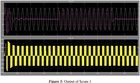
The Flexible Alternating Current Transmission Systems (FACTS) device deals with the control of power flow, alternating current of transmission line and immediately respond towards the stability problems of the system. The present paper show that how the FACTS device STATCOM enhance the dynamic response and voltage flicker in distribution network of the power systems. In MATLAB a simplified distribution system is modeled and the find out the desired objectives. D-STATCOM changes from inductive to capacitive operation, the modulation index of the PWM inverter is increased from 0.56 to 0.9 which corresponds to a proportional increase in inverter voltage. Reversing of reactive power is very fast, about one cycle, as observed on D-STATCOM current. Observed on Scope that voltage fluctuation at bus B3 is now reduced to +/- 0.7 %. The D-STATCOM compensates voltage by injecting a reactive current modulated and varying between 0.6 pu capacitive when voltage is low and 0.6 pu inductive when voltage is high.
Keywords: Flexible AC Transmission Systems (FACTS); STATCOM; Voltage Stability; Bus Voltage; Dynamic Response; Voltage Mitigation; Voltage Sag.
Cite This Article: V. Siva Brahmaiah, and Manav Adhikari, “THE ANALYSIS OF DYNAMIC RESPONSE AND VOLTAGE FLICKER WITH STATCOM ON DISTRIBUTION NETWORK” International Journal of Engineering Technologies and Management Research, Vol. 4, No. 4(2017), 27-33. DOI: https://doi.org/10.29121/ijetmr.v4.i4.2017.79.
1. INTRODUCTION
Dynamic response and voltage flicker is an important issue in the control of electric power systems. Reactive power increases the transmission system losses and reduces the power transmission capability of the transmission lines.
Http://www.ijetmr.com©International Journal of Engineering Technologies and Management Research [27-33] Today’s power transmission and distribution systems face increasing demands for more power with better quality and higher reliability at lower cost. Developing countries can apply versatile voltage regulation and system stabilization measures in order to effectively utilize the existing transmission networks. The use of power electronics in the form of SSSC, STATCOM and UPFC is well-established independent of the specific application.
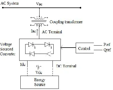
A STATCOM is a controlled reactive-power source. It provides the desired reactive-power generation and absorption entirely by means of electronic processing of the voltage and current waveforms in a VSC.A STATCOM block diagram shown in Figure 1.
Figure 1: Block diagram of STATCOM
1.1.BASIC OPERATION
Figure 2 shows the basic principle of STATCOM operation, it is as follows. The VSI generates a controllable AC voltage source behind the leakage reactance. This voltage is compared with the AC bus voltage system, when the AC bus voltage magnitude is above that of the VSI voltage magnitude, the AC system sees the STATCOM as an inductance connected to its terminals. Otherwise, if the VSI voltage magnitude is above that of the AC bus voltage magnitude, the AC system sees the STATCOM as a capacitance connected to its terminals. If the voltage magnitudes are equal, the reactive power exchange is zero.
Http://www.ijetmr.com©International Journal of Engineering Technologies and Management Research [27-33] STATCOM operation Details of the implementation and use of the STATCOM models proposed here is discussed in regard to MATLAB model. However for this application the VSI is modeled to operate in steady state power system mode, which regulates the voltage during voltage sag event.
1.2.VOLTAGE SOURCE INVERTER (VSI)
The major aim of a VSI is to generate an AC voltage from a DC one that is because of it is often referred to as a DC–AC converter or inverter. It is able to generate a symmetric AC voltage with a desired magnitude and frequency, which can be fixed or varied according to the application. The voltage source inverter is the building block of the STATCOM and other FACTS devices. The three-phase basic configuration is called six-pulse inverter, consisting of two IGBT bridge circuit.
2. METHODOLOGY
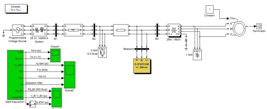
A simple circuit of power system is simulated in MATLAB with D-STATCOM. Consists of three buses, two feeders, variable load and programmable source.
The following figure 3 shows the MATLAB simulation model of STATCOM with distribution network.
Http://www.ijetmr.com©International Journal of Engineering Technologies and Management Research [27-33] Figure 4: STATCOM Configuration in Distribution System
3. RESULTS
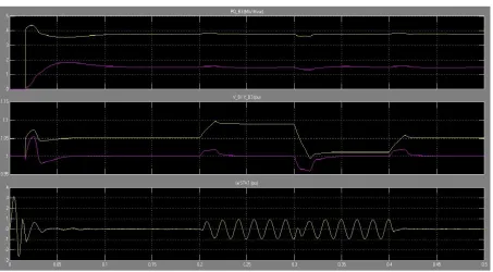
Http://www.ijetmr.com©International Journal of Engineering Technologies and Management Research [27-33] Figure 6: Output of Scope 2
Figure 7: Output of Scope 3
4. CONCLUSIONS
Http://www.ijetmr.com©International Journal of Engineering Technologies and Management Research [27-33] maintain a 1 pu voltage (Q changes from +2.7 MVAR to -2.8 MVAR). When the D-STATCOM changes from inductive to capacitive operation, the modulation index of the PWM inverter is increased from 0.56 to 0.9 (trace 4 of Scope2) which corresponds to a proportional increase in inverter voltage. Reversing of reactive power is very fast, about one cycle, as observed on D-STATCOM current.
Without D-STATCOM, B3 voltage varies between 0.96 pu and 1.04 pu (+/- 4% variation). With D-STATCOM observe on Scope 3 that voltage fluctuation at bus B3 is now reduced to +/- 0.7 %. The D-STATCOM compensates voltage by injecting a reactive current modulated at 5 Hz (trace 3 of Scope3).
5. ACKNOWLEDGMENT
This research paper is supported by Mr. V. Siva Brahmaiah, Electrical Department, Mewar University, Chittorgarh,
6. REFERENCES
[1] SankalpAsawa, Sam Al-Attiyah, “Impact of FACTS device in Electrical Power
System”(ICEEOT) - 2016
[2] B. U. Musa, Musa Mustapha “Modelling and Simulation of STATCOM for Reactive Power and Voltage Control”,(JMEST), ISSN: 3159-0040, Vol. 2 Issue 2, February – 2015
[3] Ricardo Da´valos M., Juan M. Ramı´rez*, Rube´nTapia O., January 2005, "Three-phase multi-pulse converter StatCom analysis", International Journal of Electrical Power & Energy Systems, Vol. 27, Issue 1,Pages 39-51.
[4] A. F .Huweg, S. M. Bashi MIEEE, N. Mariun SMIEEE “Application of Inverter Based Shunt Device For Voltage Sag Mitigation Due to starting of an induction motor load”, C I R E D, Turin, 6-9 June 2005
[5] Sannino, A., Svensson, J. “Application of converter based series device for voltage sag mitigation to induction motor load”, Power Tech Proceedings, 2001 IEEE Porto,vol.2, Pages 6.
[6] N.G. Hingorani, L. Gyugyi, “Understanding FACTS : Concepts and Technology of Flexible AC Transmission systems” IEEE Power Engineering Society, IEEE press, Delhi 2001.