HARMONIC ELIMINATION FOR SUPER – MULTIPLE
OF SUPPLY FREQUENCY CONVERTER BASED ON
DISCRETE AMPLITUDE MODULATION BY USING
DOUBLE SHIFT COMB FILTER TECHNIQUE
Ibraheem Mohammed Khaleel
Computer and Communications Engineering Dept.
AL- Rafidain University College, Baghdad, Iraq
[email protected]
Abstract: One of most important challenge that face industrial electronics is to enhance the performance of converters used switching device. This paper gives a sufficient method to reduce total harmonic distortion for super- multiple of supply frequency based on converting (50) Hz to (400) Hz, this method depends upon comb filter technique, by shifting the main supply by suitable two angles phase shift using two phase shifting transformers and applying these sources to three converters to create three distorted ( 400) Hz waveforms each one have different displacement angle, three waveforms added to gather in order to create new 400Hz has low distorted waveform, applying this method will reduce the THD from 70% to 36 %.
Keywords
: comb filter, frequency changers, PTSs, harmonic elimination.
1. INTRODUCTION
For AC to AC frequency multiplier based on amplitude modulation there is a big advantage over the other converters that is this converter doesn't need for DC link, but the output of this converter has a large amount of total harmonic distortion about 70% [1], so that to use this converter in industrial electronics we must reduce THD to acceptable value, in order to use the converter in high frequency applications such as airplane and aircraft power supplies which operates with THD about 20% [2] and induction heating supplies which operates with waveforms have THD about 30%[3] . One of important techniques used to reduce THD is
Journal homepage: www.mjret.in
comb filter which is based on shifting the spectrum of distorted output waveform of converter by a suitable phase shift and add the shifted spectrum with original spectrum the resultant of this technique will be a frequency spectrum with low THD [ 4 ], as shown in Fig.1
.
For 400 Hz converter (AC to AC frequency changer), the frequency spectrum of the converter shows large magnitudes for 300 Hz sub harmonic and 500 Hz harmonic, these most predominant frequencies with respect to magnitude of fundamental caused increasing in amount of THD as shown in Fig.2.
Fig.2: Spectrum of AC to AC frequency changer operates at 400 HZ
According to this fact and since that the THD completely depends upon the magnitude of the harmonics and sub harmonics appears in the frequency spectrum of distorted waveform and the magnitude of fundamental frequency as shown in equation (1).
1 (1)
Where An represent the magnitude of harmonics and sub harmonics and A1 represent the
magnitude of fundamental frequency. The comb filter must be designed to eliminate or reduce these tedious frequencies, unfortunately the comb filter technique established by shifting the distorted output of the converter by a suitable angle, the suggested phase shift depends upon the desired frequency that is wants to eliminate or reduced as shown in equation (2)[4].
Phase shifter Vin (jw)
high THD
Vout (jw) Low THD
+
+
(2)
The ordinary comb filter operates with phase shift 1200 which can be investigated by using the balanced three phase outputs of the converter, this phase shift cannot applied for AC to AC frequency multiplier operates with N=8 to generate 400 Hz important frequency in industrial electronics, because this filter with phase shift of 120o cannot eliminate or reduce 300Hz and 500 Hz harmful frequencies without effect the magnitude of the 400Hz fundamental frequency as shown Fig.3.
Fig.3: Frequency response of ordinary comb filter
A new approach suggested in order to enhanced the performance of comb filter by inserting anther phase shifter and makes the comb filter operates with two phase shifters at two different angles, in this paper a new approach will be discussed, proved, and applied for (AC to AC) frequency multiplier operates with N=8 in order to eliminate or reduce most effective harmful harmonics (300Hz and 500Hz) by changing the positions of (zeros against frequency) that appears in the transfer function of the comb filter.
2. PROPOSED COMB FILTER
Fig.4: Proposed double shift comb filter
2.1 Mathematical model
Suppose that the comb filter capable to shift distorted output of frequency multiplier with two angles ( so that the output of enhanced comb filter can be determine in frequency domain as shown in equation (3):
- -
(3)
- - (4)
So that the transfer function of double shift transfer function is
- - (5)
- - and - - (6)
according that
- - (7)
W o po g p p (θ θ ), this
can be illustrated as shown in equation (8):
and (8)
Finally we can estimate the magnitude of transfer function as function of and as
shown in equation (9)
-
(9)
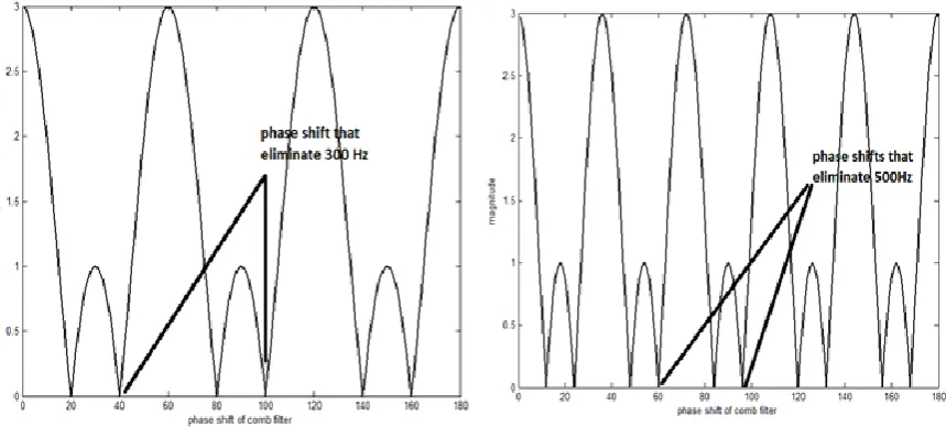
Fig.5: Magnitude of transfer function against phase shift variation at certain frequency
As shown in Fig.5 after illustrating equation (9) at f=300Hz and f=500Hz there where many zeros in the variation the magnitude of transfer function against the variation of angles of phase shifters at theses desired frequencies , and the phase angles which eliminate both 300Hz and 500Hz lies between ( 950 and 1000 ), and to estimate the angles of the shifters for double comb filter the magnitude of transfer function was estimated in suggested range of angles to get an optimum values of angles needed to eliminate tedious frequencies as shown in table.1.
Normalized
magnitude of
400Hz
Normalized
magnitude of
300Hz
Normalized
magnitude of
500Hz
95 -95 2 0.015 0.005
96 -96 2.2 0.01 0
97 -97 2.2 0.005 0.005
98 -98 1.2 0.005 0.005
99 -99 1.2 0.005 0.01
100 -100 1.5 0 0.015
Table 1: Phase shift variation against magnitude of fundamental and predominate harmonics
From table.1 the optimum angles phase shifting that eliminate 300 Hz and 500 Hz for double o o ( θ 970 θ -970 ), because at these angles the normalized magnitude of transfer function for double comb filter gives maximum amplitude for fundamental frequency , while for harmful desired frequencies the magnitude of transfer function is minimum.
phase-shifting methods, however, when the phase-shift calibration is inaccurate, these methods cannot eliminate the effects of non-sinusoidal characteristics" [5].
According to this serious problem, ,the phase shifters location must be change in order to shift sinusoidal waveform, the phase shifters inserted to displace the main supply with suitable angles , the improved model with new position of phase shifters as shown in Fig.6.
Fig.6: Improve double shifting comb filter
the improvement of double comb filter harmonic reduction technique depends upon time shifting theorem which is one of the properties of Fourier analysis which state that if Fourier transform of F{f(t)} = F(ω) so that Fourier transform of F{f(t − t0)} = e−iωt0F(ω) [6] where( tO) corresponding time equivalent to phase shift, which can be established by
for (f=50Hz supply frequency) so that a new transfer function for system shown in
Fig(6) must be determined.
Assuming the main supply with sinusoidal wave form has frequency spectrum of and the output of converter 1 in frequency domain define as , and the frequency
spectrum of the output of phase shifters (1 and 2 ) as - and -
respectively, the output of converters (2 and 3) will be - and - depending upon the linearity property the output of overall system can be defined as:
- - (10)
According time shifting theorem the output of all converters (1,2,4) have the same magnitude at each frequency appears in the frequency spectrum but the output of converters (1,2) shifted by (θ1 and θ2) respectively[7] according that
- - (11)
- - (12)
The transfer function for overall system shown in equation (13) is symmetrical to a transfer function of proposed comb filter in equation (5) which o p p po ( θ θ ) so that a suitable phase shifter want to be established which is capable to shift the main supply with (97o) and ( – 97o) in order to eliminate tedious frequencies that makes the THD very high.
3. PHASE SHIFTER DESIGN USING PHASE SHIFTING TRANSFORMER
Phase shifting transformers are special forms of transformers able to control active power by regulating the voltage phase angle difference between two nodes of the power system [8]. Symmetric PSTs are which they have constant or nearly constant input and output voltages across the phase shift range (the input and output voltage vectors would describe circular arcs through the phase shifting range) [9]. This is achieved by adding a symmetrical PSTs voltage to the input and output phase angle, as shown in Fig.7
However the balanced main supply cannot shifted with (97o and -97o), since the phase shift transformer gives (30o and -30oin linear region of shifting)[9], the main supply must be shifted in previous range which is not comparable with is estimated to eliminate not useful frequencies, so that two shifting transformers used to shift the balanced three phase sources each one by( 23o and -23o) to get three main sources described as (A, A/, A//,B, B/, B//,C,C/,C// ) which subjected to three (AC to AC frequency multiplier), the resultant phasor diagram can be describe as shown in Fig.8.
The resultant phases that produced by the two phase shifting transformers are almost balanced, and the phase angles of each phase shown in table.2.
Main
supply
Applying 23o phase shifter Applying - 23o phase shifter
Phase (A) A/=23o considered phase B shifted by -97o
A//=-23o considered phase C shifted by 97o
Phase (B) B/=153o considered phase C shifted by -97o
B//=97o considered phase A shifted by 97o
Phase (C) C/=-97o considered phase A shifted by -97o
C//=-143o considered phase B shifted by -97o
Table2: Shifting sequences and new resultant phases
From table (2), phases B// and C/ considered to be phase A shifted by (97o and -97o) respectively, phases A/ and C// considered to be phase B shifted by (97o and -97o), and phases A// and B/ considered to be phase C shifted by (97o and -97o), all of these phases are distorted waveform, but after applying summing of shifted phases with zero with original output of frequency changer the resultant waveform has low total harmonic distortion, according that the output of improved system for each phase can be established in equations( 12, 13, 14).
A///=A+C/+B// (12)
B///=B+A/+C// (13)
C///=C+A//+B/ (14)
4. SIMULATION AND RESULT
The proposed enhanced comb filter shown in Fig(6) was simulated using MATLAB
SIMULINK package as shown in Fig.9, the system established using three AC to AC frequency changers, the chargers ( 2) and (3) designed to work with suggested phase shifts of ( 23o) and (- 23o) respectively these angles implemented using two shifting transformers in order to get new 400 Hz frequency phases ( A/, A//,B/, B//, C/, C//) these resultant 6 phase must be almost balanced, converter (1) used to generate 400Hz from main balanced supply directly to generate phases ( A, B,C) the summing procedure was implemented using three multiwinding transformers.
Fig.10: Outputs of AC to AC converters with phase angle of each phase
The overall output of the enhanced system after applying summing procedure using multiwinding transformers, the summing procedure according equations ( 12, 13, 14) result three phase low distorted waveforms as shown in Fig.11.
As shown in Fig.11 the output is almost balance and showing an enhancement in performance with respect with the output of converter without applying enhanced double shifting comb filter, also after estimating harmonic analysis which result frequency spectrum illustrated using FFT analysis of MATLAB SIMULINK package shown in Fig.12.
Fig.12: Frequency spectrum of enhanced AC to AC frequency multiplier
From Fig.12 we can notice that the predominates harmonics appears in original spectrum for (AC to AC frequency multiplier) that is makes the value of total harmonic distortion eliminated to minimum value, to estimate THD the distortion factor for each remaining harmonic can be determined as shown in table.4.
Apparent frequency
in the spectrum ( Hz)
Distortions factor of
each frequency %
Apparent frequency
in the spectrum( Hz)
Distortions factor of
each frequency %
50 0 550 0
100 23.4 600 7
150 0 650 0
200 29.3 700 0
250 0 750 0
300 0 800 0
350 0 850 0
400 Fundamental 900 0
500 25 1000 0
Table4: Distortion factor of apparent frequencies appears in the spectrum of AC to AC
frequency multiplier
Finally after estimation of THD the value of this important value used to measure the performance of any converter used in industrial electronics, the use of enhanced comb filter technique makes THD reduced to 36% which is considered as good improvement in the performance since the THD of the converter before applying the new approach was 70%, however this improvement considered to be applicable in application of high frequency for power electronics.
5. CONCLUSION
Most important application in industrial electronic was changing of frequency of main supply by mean of switching devices, this application suffered from huge amount of total harmonic distortion, one of the techniques used to reduce THD is comb filter, this technique used with double angles of phase shifting ( θ θ ), the big problem suffered during this work is to shift non sinusoidal waveforms, the problem was overcome by shifting the source by a suitable angles that eliminate harmful frequencies in distorted output of the frequency changer, however the use of double shifting method which has been used in this paper makes good reduction in THD which decreased from 70% to 36% which is considered to be an acceptable value with respect to previous methods which gives the same range of THD, however the disadvantage of proposed technique is the use of phase shifting transformers which have high cost to implement, so that as a future work we need to investigate a low cost phase shifter can be used to implement the proposed enhanced comb filter.
REFERENCES
[1]. M hamm d S M A Kh bak, Ibrah m M Khal l, M hamm d Laz m,” A S p r – Multiple of S pply fr q y C v r r Ba d D r Ampl d M d la ”, ICAS OR r al f engineering, India ,January , 2014.
[2]. G.Murali Krishna, V.V.N.Mur hy, K Lak hm Ga h, ,” HD A aly f Symm r al a d A ymm r al Cascaded H-Br dg M l l v l I v r r h P Array ” IJAIR, India,2012.
[3]. A g la Iagăr,” P r Q al y Pr bl m G ra d by L Fr q y C r l I d F r a ”, P l h a U v r y m ş ara R ma a,Nov 23, 2011.
[4]. Kh bak, M hamm d S M A , a d Laz m M ,” E v l p Cy l v r r Harm R d U g Comb F l r,” h h I r a al M l -Conference on Systems, Signals and Devices SSD '09, 2009. [5]. K H b , B F Or b, a d D I Farra ,” Pha h f g f r dal av f rm h pha -shift
rr r ,” H b al l , 4/Apr l 995/J Opt. Soc. Am. A.
[6]. Erwain Kreyszig " Advanced Engineering Mathematics" Join Willy & Sons, Sixth edition 1988.
[7]. HELM,"Properties of the Fourier Transform",," (VERSION 1: March 18, 2004): Workbook Level 2 24.2 [8]. Hertem , Jody Verboomen, Dirk Van, " Influence of phase shifting transformers and HVDC on power
system losses