Design and Implementation of Biomorphic Palm
using Arduino Programming
Sreerag S Rahul R Nair
B. Tech Student B. Tech Student
Department of Electronics & Communication Engineering Department of Electronics & Communication Engineering NSS College of Engineering, Palakkad, Kerala, India NSS College of Engineering, Palakkad, Kerala, India
Vishnu K Vishnu S Dev
B. Tech Student B. Tech Student
Department of Electronics & Communication Engineering Department of Electronics & Communication Engineering NSS College of Engineering, Palakkad, Kerala, India NSS College of Engineering, Palakkad, Kerala, India
Abstract
The developing technology of the future, biomorphic robotics, inside Ethical dimensions, aids the humans for accomplishing tedious tasks which can’t be done by them due to physical limitations. Biomorphic robotics is a sub discipline of robotics focused on the emulating mechanics, sensing, structural, and computing systems of animals. They deal with how biologically inspired principles can be used to negotiate complexities of real world. In this paper we present the design and implementation of a biomorphic palm using one of the most powerful open source electronic prototyping platforms Arduino. The software used will be Arduino IDE and the communication between human palm and robotic palm will be established wirelessly by XBEE modules.
Keywords: Biomorphic Palm, Arduino, Microcontoller, UNO R3, Xbee, Servo Motors
_______________________________________________________________________________________________________
I.
I
NTRODUCTIONSimplicity and high accuracy have become the two contradictory needs of any industrial process. By introducing autonomous robotic applications, tedious tasks can be accomplished keeping the demands of the accuracy and in mind. However, developing these applications for industries specific to countries like India, where cheap labour is available, becomes a major problem to be tackled in terms of cost. Human control over the developed robotic system is the most significant aspect of robotics. Keeping this in mind an idea of a robotic palm mimicking the actions of a human palm was developed. A study regarding the possibilities of this idea was conducted and exciting results were obtained. As a second stage selection of hardware for the implementation was done giving priority to low cost and simplicity. Thus Arduino[1][2] platform satisfying both the needs stated above was selected. This project is a practical application of the basic principles of electronics and wireless communication. The biomorphic pal m system consists of flex sensing system , a Micro controller for processing the sensor inputs , a radio frequency transmitter- receiver pair , servo motors and power transfer cords and a mechanical palm made of plastic tubes. The system presented here is a prototype and can be developed much more for better performance and efficiency.
The system is divided in to main two parts 1) Power gloves
2) Biomorphic Palm
The power gloves are attached with the 5 flex sensors which are capable of chemically varying their resistance, with respect to the angle they are flexed to. A circuit is designed for converting this variation in resistance to corresponding voltage equivalent. So basically the power gloves act as a resistance to voltage converter. This analogue voltage is given to the Arduino[2] embedded system as an input to the atmega 328 microcontroller[3] through the analogue input pin provided in the board. The processor maps these values to a range of 0 to 256 and is radiated to space using the Xbee[4] (2mw) transmitter chip on board. The biomorphic palm is attached with another Arduino system with a receiving Xbee chip paired with the transmitter in the gloves. The receiver receives the signal and is fed to the processor. The mapped values are converted to the original values and is made available at the output pins from which they are applied on to the servo motors. The servo motors responds to the voltage and the movements of the motor is transferred to the palm using power transfer cords attached to the motors.
II.
S
YSTEM DESIGNA modular approach always simplifies the design of any system .Hence this project was divided in to modules and each module were individually constructed and was assembled at the final stage. The Biomorphic palm system dealt in this project can be divided in to 4 modules.
1) Sensor Network
2) Coding and Transmission 3) Receiver
4) Mechanical Palm.
Fig. 1: Basic System Structure
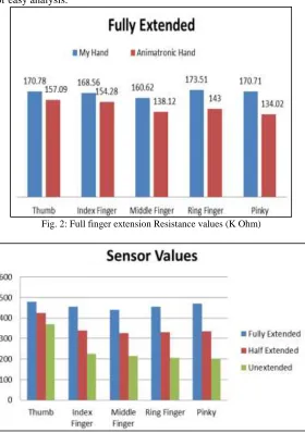
The positions of the 5 fingers were detected using flex sensors. Flex sensors[5] are basically variable resistance. They are able to vary their resistance in response to the bending occurred. Tests were conducted to have the idea about the maximum and minimum resistance values of the sensors in the range of angles at which bending is required. A basic voltage divider circuit can be used for understanding the maximum and minimum resistance values available from the sensors. The results were tabulated and converted to bar graphs for easy analysis.
Fig. 2: Full finger extension Resistance values (K Ohm)
Fig. 4: Voltage Divider circuit for determining resistance values
Making use of above circuit the range of values of resistance and their corresponding voltage converted value for angle at which the sensor is bend was determined. This value was mapped on to a range of 0 to 255 corresponding to 10 bit ADC available in the board. This digitized value was transmitted using Xbee 2 chip.
The Digitized values transmitted by the transmitter were received by the receiver paired with the transmitter. This values were converted back to their original values and was made available at the output ports. Servo motors of 1.4Nm torque and operating range of 4.8-6 V were used for powering up the biomorphic palm. High tensile plastic wires were used to deliver the motor power to the fingers which were precisely designed using plastic tubes and pipes.
III.
H
ARDWAREFlex Sensors A.
The flex sensor is a sensor which varies its resistance when they are bend through an angle. As bending angle increases its resistance increases. One side of the sensor is printed with a polymer ink that has conductive particles embedded in it. When the sensor is straight, the particles give the ink a resistance of about 30k Ohms. When the sensor is bent away from the ink, the conductive particles move further apart, increasing this resistance. When the sensor straightens out again, the resistance returns to the original value. By measuring the resistance, it is possible determine how much the sensor is being bent.
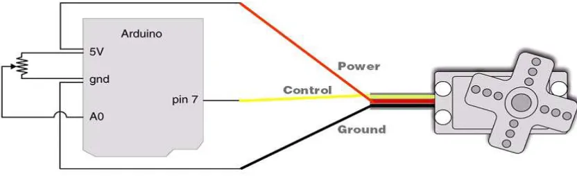
Servo Motors B.
Servo refers to an error sensing feedback control which is used to correct the performance of a system. Servo or RC Servo Motors are DC motors equipped with a servo mechanism for precise control of angular position. The RC servo motors usually have a rotation limit from 90 to 180. But servos do not rotate continually. Their rotation is restricted in between the fixed angles.
Fig. 5: Servo motor connection scheme
XBEE PRO C.
primarily used in instances where an existing protocol cannot tolerate changes to the data format. AT commands are used to control the radios settings. In API mode the data is wrapped in a packet structure that allows for addressing, parameter setting and packet delivery feedback, including remote sensing and control of digital I/O and analogue input pins.
Arduino Uno R3 D.
The Arduino Uno is a microcontroller board based on the ATmega328. It has 14 digital input/output pins (of which 6 can be used as PWM outputs), 6 analogue inputs, a 16 MHz ceramic resonator, a USB connection, a power jack, an ICSP header, and a reset button. It contains everything needed to support the microcontroller; simply connect it to a computer with a USB cable or power it with an AC-to-DC adapter or battery to get started. The Uno differs from all preceding boards in that it does not use the FTDI USB-to-serial driver chip. Instead, it features the Atmega16U2 (Atmega8U2 up to version R2) programmed as a USB-to-serial converter.
Specifications 1)
Microcontroller ATmega328 Operating Voltage 5V
Input Voltage 6-20V
Digital I/O Pins 14 (of which 6 provide PWM output) Analogue Input Pins 6
DC Current per I/O Pin 40 mA DC Current for 3.3V Pin 50 mA
Flash Memory 32 KB (ATmega328) of which 0.5 KB used by boot loader SRAM 2 KB (ATmega328)
EEPROM 1 KB (ATmega328) Clock Speed 16 MHz
IV.
C
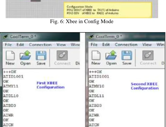
ODINGXbee Transmitter and receiver needs to be configured so as to initiate communication. For this purpose Xbees are connected in configuration mode.
Fig. 6: Xbee in Config Mode
\\ Transmitter Side Code int ThumbFngr = 0; int IndexFngr = 1; int MiddleFngr = 2; int RingFngr = 3;
int BabyFngr = 4; // Declaration of Finger Voltage Variables int ThumbVal=0;
int IndexVal=1; int MiddleVal=2; int RingVal=3;
int BabyVal=4; //Declare and Initialise Variables for Defining Static position of Palm. byte ThumbServo=0;
byte IndexServo=0; byte MiddleServo=0; byte RingServo=0;
byte BabyServo=0; //Declare Servo Variables for Voltage Value Mapping void setup()
Serial.begin(9600); //Setting Baud Rate and Initiating Transmission void loop()
ThumbVal = analogRead(ThumbFngr); // Getting Finger Value Inputs through Analog Pins IndexVal = analogRead(IndexFngr);
MiddleVal = analogRead(MiddleFngr); RingVal = analogRead(RingFngr); BabyVal = analogRead(BabyFngr);
if (ThumbVal <400) ThumbVal = 400; // Limiting all Received Values to a fixed Range else if (ThumbVal >920) ThumbVal = 920;
if (IndexVal <400) IndexVal = 400; else if (IndexVal >920) IndexVal = 920; if (MiddleVal <400) MiddleVal = 400; else if (MiddleVal >920) MiddleVal = 920; if (RingVal <400) RingVal = 400;
else if (RingVal >920) RingVal = 920; if (BabyVal <400) BabyVal = 400; else if (BabyVal >920) BabyVal = 920;
ThumbServo = map(ThumbVal, 920, 400, 255, 0); // Mapping all values to a range of 0 to 255 IndexServo = map(IndexVal, 920, 400, 255, 0);
MiddleServo = map(MiddleVal, 920, 400, 255, 0); RingServo = map(RingVal, 920, 400, 255, 0); BabyServo = map(BabyVal, 920, 400, 255, 0);
Serial.print(ThumbServo); // Transmitting Data to Receiver Serial.print(IndexServo);
Serial.print(MiddleServo); Serial.print(RingServo); Serial.print(BabyServo); delay(100);
\\ Receiver Side Code include<Servo.h >
Servo ThumbFinger; // Creating Servo Objects Servo IndexFinger; Servo MiddleFinger; Servo RingFinger; Servo BabyFinger; byte ServoThumb=0; byte ServoIndex=0 byte ServoMiddle=0 byte ServoRing=0
ThumbFinger.attach(2); // Attaching Pins to Servo Objects IndexFinger.attach(3);
MiddleFinger.attach(4); RingFinger.attach(5); BabyFinger.attach(6); void loop()
if(Serial.available() >=5)
ServoThumb = Serial.read(); // Reading Received Values ServoIndex = Serial.read();
ServoMiddle = Serial.read(); ServoRing = Serial.read(); ServoBaby = Serial.read();
ThumbFinger.write(ServoThumb); // Sending Values to Respective Pins IndexFinger.write(ServoIndex);
MiddleFinger.write(ServoMiddle); RingFinger.write(ServoRing); BabyFinger.write(ServoBaby)
V.
F
UTURE WORKSThe XBEE Modules which provides a range limitation for our work need to be replaced with internet protocols, so that surgeries could be done from remote places via internet. The thought of development of a complete Biomorphic Robot can be put into effect. Efforts to implement this system for the development of fire force rescue missions and military applications. To avoid the misuse of the technology security features like voice command recognition can also be implemented.
VI.
C
ONCLUSIONKeeping aside the difficulties face during design and development the system performed very well under all circumstances. The values picked up by the flex sensors were transmitted, received and decoded properly and the servo motors could be operated satisfactorily. The overall system performance was very good and was monitored and tested with different gestures.
R
EFERENCES[1] O'Reilly Arduino cook book - MICHEAL MARGOLIS
[2] “Different Applications of Arduino” by Maha M Lashin Vol 5 Issue 6 IJMET IAEME [3] ww.atmel.com
[4] www.sparkfun.com
[5] “What are flex sensors?” imagesco.com/sensors/flex-sensor.html