International Journal of Advances in Engineering Research http://www.ijaer.com
(IJAER) 2017, Vol. No. 13, Issue No. I, January e-ISSN: 2231-5152, p-ISSN: 2454-1796
DESIGN AND DEVELOPMENT OF MOULD FOR
COMPOSITE SPECIMEN SHEET
K.Kalyani, Chunchu Sravanthi
Assistant Professor,
Department of Mechanical Engineering Anurag Group of Institutions Hyderabad, Telangana, India.
ABSTRACT
Composite materials are engineered or naturally occurring materials made from two or more constituent materials with significantly different physical or chemical properties which remain separate and distinct at the macroscopic or microscopic scale within the finished structure. The use of composite materials is rapidly growing in both the automotive and aerospace industries as designers strive to produce the lightest possible design while retaining optimal strength. Moulding is the process of manufacturing by shaping pliable raw material using a rigid frame or model called pattern. A mould is a hollowed-out block that is filled with a liquid like plastic, glass, metal, or ceramic raw materials. The liquid hardens or sets inside the mould, adopting its shape.In this paper, the design of mould for making a composite specimen sheet is made. The material used for this composite sheet is glass fibre.
Glass fibre reinforced polymers (GFRP) are widely used in the aeronautical and the automotive industry mainly due to their high specific mechanical properties. During the last decades, the aerospace industry focus its research in producing multi-functional materials, driving design parameters being the weight reduction with increased mechanical properties as well as monitoring their structural health by means of sensing capability.
Keywords: composite, macroscopic, microscopic, Polymer.
INTRODUCTION
A composite is commonly defined as a combination of two or more distinct materials, each of which retains its own distinctive properties, to create a new material with properties that cannot be achieved by any of the components acting alone. Using this definition, it can be determined that a wide range of engineering materials fall into this category. For example, concrete is a composite because it is a mixture of Portland cement and aggregate. Fiberglass sheet is a composite since it is made of glass fibers imbedded in a polymer.
International Journal of Advances in Engineering Research http://www.ijaer.com
(IJAER) 2017, Vol. No. 13, Issue No. I, January e-ISSN: 2231-5152, p-ISSN: 2454-1796
can be metal, ceramic, or polymer. Typically, reinforcing materials are strong with low densities while the matrix is usually a ductile, or tough, material.
Some of the common classifications of Reinforced plastics
Metal-matrix composites
Ceramic-matrix composites
Sandwich structures
Concrete
Composite materials can take many forms but they can be separated into three categories based on the strengthening mechanism. These categories are dispersion strengthened, particle reinforced and fiber reinforced. Dispersion strengthened composites have a fine distribution of secondary particles in the matrix of the material. These particles impede the mechanisms that allow a material to deform. (These mechanisms include dislocation movement and slip, which will be discussed later). Many metal-matrix composites would fall into the dispersion strengthened composite category. Particle reinforced composites have a large volume fraction of particle dispersed in the matrix and the load is shared by the particles and the matrix. Most commercial ceramics and many filled polymers are particle-reinforced composites. In fiber-reinforced composites, the fiber is the primary load-bearing component. Fiberglass and carbon fiber composites are examples of fiber-reinforced composites.
If the composite is designed and fabricated correctly, it combines the strength of the reinforcement with the toughness of the matrix to achieve a combination of desirable properties not available in any single conventional material. Some composites also offer the advantage of being tailor able so that properties, such as strength and stiffness, can easily be changed by changing amount or orientation of the reinforcement material. The downside is that such composites are often more expensive than conventional materials.
Composite materials are engineered or naturally occurring materials made from two or more constituent materials with significantly different physical or chemical properties which remain separate and distinct at the macroscopic or microscopic scale within the finished structure.
The use of composite materials is rapidly growing in both the automotive and aerospace industries as designers strive to produce lightest possible design while retaining optimal strength.
International Journal of Advances in Engineering Research http://www.ijaer.com
(IJAER) 2017, Vol. No. 13, Issue No. I, January e-ISSN: 2231-5152, p-ISSN: 2454-1796
Fig 1.1 Examples of composite materials
DESIGN OF MOULD CAVITY
The 8 mil thickness glass fabric used in this project is a bi-directional fabric and this fabric stretches vary easily. Due to the uneven cutting of the bi-directional reinforcement and also deformation of the fabric during the lay-up in the cavity and resin application process, it is expected that on the perimeter of the laminate there will be variation or non-uniformity in the reinforcement and the resin content. Hence it is a must to have trimming elements on the perimeter of the laminate which is called moldings.
Moulding = Useful laminate + Trimming allowance.
Assuming a uniform trimming element of 20mm on the perimeter, the size of the moldings could be 320*320mm.
International Journal of Advances in Engineering Research http://www.ijaer.com
(IJAER) 2017, Vol. No. 13, Issue No. I, January e-ISSN: 2231-5152, p-ISSN: 2454-1796
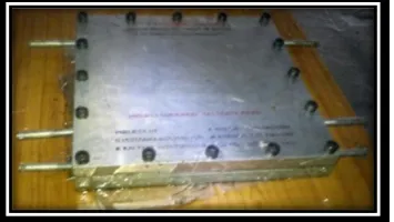
Fig. 3.5, Mould Cavity
The mould design is based upon some of the design principles. They are
DESIGN PRINCIPLES
In the view of high temperature curable epoxy resin decided to be used, the mould should be able to withstand a high temperature of 2200c under a contact pressure of a maximum for the mould.
Fig.3.6.1, Mild steel material for mould
1. If the thickness of the laminate is less than 4mm, then while manufacturing the required mould bending might occur which further reduces the thickness and the quality of the laminate. So, in the view of the stiffness steel is used here. Deformation also depends on 'EI'. More is the value of EI less is the bending. This is another reason why steel is selected instead of other materials like aluminum. On this basis to make sure that the mould does not bend, the total thickness of the mould made of steel is 16mm.
International Journal of Advances in Engineering Research http://www.ijaer.com
(IJAER) 2017, Vol. No. 13, Issue No. I, January e-ISSN: 2231-5152, p-ISSN: 2454-1796
and excess resin if any should be facilitated to be squeezed out and the mould design should cater to that. Hence the components called spacers are developed which are placed between the top and bottom plates respectively. These also provide us with the cavity into which the glass fabric plies must be placed for the manufacture of the laminate. These spacers also contain the resin overflow holes and are parallel to the plan form of the laminate since the resin bleed out is from the edge of the ply.
3. After placing all the plies into the cavity and after applying resin, the mould must be closed and must be placed under a hydraulic press where a load of 20 tones will be applied on it. During this process the excess resin comes out and gets deposited on all of the mould. Once this cools then becomes hard and dismantling the mould would be made difficult thus making it difficult for the removal of the laminate.
4. In view of flooding of the mould pieces during the mould closing operation by resin which will set and cure subsequently during operations, the mould design should be made such that the mould pieces can be cleaned easily. Hence all the spacer plates have been made as separate piece and bolted to the die plate and this also facilitates to the surface grinding of the mould. A new and a different sized laminated can be produced only by changing the size of the spacers and by making the spacers as separate components easy removal of the composite laminate has been facilitated.
5. The spacers also help in containing the lay up from the lateral movement during the load application when it is in green condition. Green condition is the state in which the laminate is in uncured and undressed state. The fixing of the spacers is done with Allen screws as it is easily removable. For this the spacer thickness has to be more in order to accommodate its head.
6. Since the spacers are fastened by Allen screws to the die plate, certain basic rules like keeping an edge distance of minimum of 1.5-2 D has been practiced making the spacer width 40mm and thus stretching the die and punch plate size to 400*400 mm.
7. Not with standing all the precautions of applying wax polish and other releasing agents all over the mould components like punch, die spacer plates, bolts and external threads of bolts and internal to tapped holes, there will still be an occasion where spacer may not separate from the die plate. Hence tapped holes are provided in die plate and by inserting a screw and rotating it, the spacer can be removed. The M-16 bolts are used for fastening the spacers and if they do not come out then M-12 bolts are used to remove the spacers.
International Journal of Advances in Engineering Research http://www.ijaer.com
(IJAER) 2017, Vol. No. 13, Issue No. I, January e-ISSN: 2231-5152, p-ISSN: 2454-1796
MANUFACTURE OF LAMINATE
1. The laminate is made of fiberglass reinforcement.
2. Non-woven fiberglass mat is the most economical, while the woven fabrics produce more uniform and stronger composites, generally requiring less resin
3. The steps involved in making the laminate are :
4. Wax should be thoroughly applied to each and every corner of the mould.
5. After the wax gets dried, the releasing agent has to be applied on the lower plate of the mould.
6. The first layer of the glass fiber has to be placed on the mould containing the releasing agent.
7. The releasing agent has to be applied uniformly on the glass fiber sheet and on that the second layer of glass fiber has to be placed.
8. This process has to be repeated for required thickness.
9. The upper plate of the mould is placed over the glass fiber layers and tightened using the Allen key.
10.The mould is left undisturbed for 6 to 7 hrs for the glass fiber to form a laminate.
Fig.4.1, glass fiber and resin over the bottom plate of mould
DISMANTLING THE MOULD TO REMOVE THE LAMINATE
1. After the mould is completely cooled, start unfastening the bolts on the mould in order to remove the top plate and the spacers.
International Journal of Advances in Engineering Research http://www.ijaer.com
(IJAER) 2017, Vol. No. 13, Issue No. I, January e-ISSN: 2231-5152, p-ISSN: 2454-1796
3. Then the laminate is removed from the mould carefully. 4. The obtained glass fiber laminate is cut into desired shape.
5. That specimen is tested for its properties using the Universal Testing Machine (UTM).
Fig.4.1.1 Glass Fiber Laminate
PLY / LAMINAR / LAYER
A single layer of a laminated composite material is generally referred to as a PLY or LAMINATE. It usually contains a single layer of reinforcement, unidirectional or multidirectional. A single LAMINA is generally too thin to be directly used in any engineering application. Several layers are bonded together to form a structure termed as LAMINATE.
Properties and orientation of the lamina in a laminate are chosen to meet the laminate design requirements. Properties of a laminate may be predicted by knowing the properties of its constituent laminate. Behavior of the laminate is governed by the behavior of individual laminate.
In a laminate, each lamina may differ from another layer
Relative volumes of the constituent materials,
Form of the reinforcement used such as continuous or discontinuous fibers, woven or nonwoven reinforcement,
Orientation of fibers with respect to common reference axes,
Reinforcement’s fibers and/or matrix material may be different in each layer, as in hybrid laminates.
International Journal of Advances in Engineering Research http://www.ijaer.com
(IJAER) 2017, Vol. No. 13, Issue No. I, January e-ISSN: 2231-5152, p-ISSN: 2454-1796
EXPERIMENTAL ANALYSIS
The properties of the laminate are theoretical mentioned in the above chapter. But the laminate has certain desired properties which are proved practically by testing of the component in the laboratories. One of the tests performed for this E-glass epoxy laminate is in UTM (Universal testing machine).
UTM is the machine used for testing any kind of materials like metals and their alloys, plastics, composite materials and etc.,. The resultant properties obtained by testing the materials in UTM are ultimate tensile strength (stress), ultimate load, elongation (strain), and young’s modulus.
The specimen is prepared as per the American standards for testing in UTM
Fig.5.1.1
After the preparation of the specimen, it is taken for testing. The specimen is fixed in between the two jaws of the UTM.
Fig.5.1.2
International Journal of Advances in Engineering Research http://www.ijaer.com
(IJAER) 2017, Vol. No. 13, Issue No. I, January e-ISSN: 2231-5152, p-ISSN: 2454-1796
Fig.5.1.3
After setting of the equipments the testing started the load gradually. It bears the load till the breaking of the material. The load obtained at the breaking point of the material in the maximum ultimate load. Similarly the ultimate tensile strength is also displayed.
TEST RESULTS
S.No. Test Parameters Unit of Measurement
Results
Sample-1 Sample-2 Sample-3
1 Tensile Strength MPa 173 173 168
2 Yield Strength MPa 135 117 125
3 Elongation on 50mm GL
Percent 3.7 3.8 3.4
4 Flexural Strength MPa 246 263.8
CONCLUSION
The future has many desirable and complex challenges that need the technology parameters in the most sophisticated and improvised edition. When we are co-relating such a foresighted demand of an innovative material to supplement the arising challenges, composites hold immense potential as a promising answer to the aforesaid task.
International Journal of Advances in Engineering Research http://www.ijaer.com
(IJAER) 2017, Vol. No. 13, Issue No. I, January e-ISSN: 2231-5152, p-ISSN: 2454-1796
Composites have made its way into the most intricate fields of science and technology and sought potential scope in the fields of aerospace, Mechanical structures, acoustics, thermal engineering and many others. The standout feature that makes composite materials a cut above the rest is the ability of the material to be engineered and tailored as per the desired task. It’s a revolution in material technology that has elevated itself to the apex of material technology.
FUTURE SCOPE OF WORK
More than the E-glass fibers the born free-ECR glass fibers will be used extensively in the future as they offer a number of benefits over traditional E-glass. The E-CR glass combines the electrical and the mechanical properties of E-glass with resistance to corrosion.
REFERENCES
[1] Balram gupta, “Aerospace Materials” Vol. 1 to 5, S Chand and company.
[2] “Analysis and performance of fiber composites”, Agarwal BD and Botman LJ,Jhon
Wiley and sons.
[3] “Mechanics of composite materials”, Jones RM, Mcgraw Hill
[4] Titterton G, “Aircraft materials and processes”, 5th edition