Myoelectric control algorithm
for robot‑assisted therapy:
a hardware‑in‑the‑loop simulation study
Juan C. Yepes
1*, Mario A. Portela
2, Álvaro J. Saldarriaga
2, Vera Z. Pérez
2,3and Manuel J. Betancur
1,3Abstract
Background: A direct blow to the knee is one way to injure the anterior cruciate
ligament (ACL), e.g., during a football or traffic accident. Robot-assisted therapy (RAT) rehabilitation, simulating regular walking, improves walking and balance abilities, and extensor strength after ACL reconstruction. However, there is a need to perform RAT during other phases of ACL injury rehabilitation before attempting an advanced exer-cise such as walking. This paper aims to propose a myoelectric control (MEC) algorithm for a robot-assisted rehabilitation system, “Nukawa”, to assist knee movement during these types of exercises, i.e., such as in active-assisted extension exercises.
Methods: Surface electromyography (sEMG) signal processing algorithm was
devel-oped to detect the motion intention of the knee joint. The sEMG signal processing algorithm and the movement control algorithm, reported by the authors in a previous publication, were joined together as a hardware-in-the-loop simulation to create and test the MEC algorithm, instead of using the actual robot.
Experiments and results: An experimental protocol was conducted with 17 healthy
subjects to acquire sEMG signals and their lower limb kinematics during 12 ACL reha-bilitation exercises. The proposed motion intention algorithm detected the orienta-tion of the intenorienta-tion 100% of the times for the extension and flexion exercises. Also, it detected in 94% and 59% of the cases the intensity of the movement intention in a comparable way to the maximum voluntary contraction (MVC) during extension exer-cises and flexion exerexer-cises, respectively. The maximum position mean absolute error was 0.1◦ , 6.3◦ , and 0.3◦ for the hip, knee, and ankle joints, respectively.
Conclusions: The MEC algorithm detected the intensity of the movement
inten-tion, approximately, in a comparable way to the MVC and the orientation. Moreover, it requires no prior training or additional torque sensors. Also, it controls the speed of the knee joint of Nukawa to assist the knee movement, i.e., such as in active-assisted extension exercises.
Keywords: Assistive robotics, Electromyography (EMG) control, Powered exoskeletons,
Biomedical signal analysis, Myoelectric control
Open Access
© The Author(s) 2019. This article is distributed under the terms of the Creative Commons Attribution 4.0 International License (http://creat iveco mmons .org/licen ses/by/4.0/), which permits unrestricted use, distribution, and reproduction in any medium, provided you give appropriate credit to the original author(s) and the source, provide a link to the Creative Commons license, and indicate if changes were made. The Creative Commons Public Domain Dedication waiver (http://creat iveco mmons .org/publi cdoma in/zero/1.0/) applies to the data made available in this article, unless otherwise stated.
RESEARCH
*Correspondence: juancamilo.yepes@upb. edu.co
1 Grupo de Automática y
Diseño A+D, Cir. 1 #73-76, B22, Medellín 050031, Colombia
Background
The knee is the largest and most complex joint in the human body, and it depends on four primary ligaments, tendons, muscles and secondary ligaments to maintain its cor-rect function. One of the main ligaments is the anterior cruciate ligament (ACL). The ACL is one of the most commonly injured ligaments in the knee. A direct blow to the knee is one way to harm the ACL, e.g., during a football or traffic accident. Nevertheless, most ACL injuries occur even without any contact with an object [1].
There are many traditional methods and devices to assist treatment. The study of new, applied technologies in areas such as Bioengineering and Automation has brought research and technology in robotic platforms that replace, enhance or rehabilitate lower limb disabilities. Within these applications, robotic systems have become a benefit for the rehabilitation of lower limb pathologies [2]. These studies have focused on the devel-opment of active orthosis, also defined as exoskeletons [3–6].
For example, in the case of ACL injuries, Hu et al. [7] reported in 2016 a robot-assisted therapy (RAT) rehabilitation investigation, simulating regular walking to examine the effects of long-term interventions using RAT rehabilitation on functional activity levels after ACL reconstruction. The study reported that the RAT treatment improved exten-sor strength and walking and balance abilities.
However, ACL injuries require various rehabilitation phases with the purpose of controlling pain and swelling, restoring pain-free range of motion (ROM), improv-ing flexibility, normalizimprov-ing gait mechanics, and establishimprov-ing good quadriceps activation [8]. There are several international protocols for ACL injury rehabilitation such as the Accelerated ACL Reconstruction Rehabilitation Program of the Chester Knee Clinic & Cartilage Repair Center [9, 10], the Classic 1981 Protocol by Lonnie et al. [11], the ACL Reconstruction Rehabilitation Protocol of the Steadman Clinic [12], among others. These protocols report several rehabilitation phases for ACL injuries.
For the protocols mentioned above, there is the need to perform RAT rehabilitation of ACL injuries during other phases of the rehabilitation process before attempting an advanced exercise such as walking, e.g., when the patient is unable to execute a knee movement, due to the pain caused by the injury. In this rehabilitation phase, an active-assisted rehabilitation exercise may be conducted. During these types of activities, an external force provides assistance, mechanical or manual, since the muscle requires sup-port to complete the movement [13, 14]. Moreover, during the traditional rehabilitation process of ACL injuries, the protocol uses knee active-assisted extension exercises. The subject uses the opposite leg to restore ROM during these exercises, e.g., and the healthy leg straightens the non-healthy knee from a 90◦ flexion to 0◦ [15].
Therefore, the specific problem addressed in this paper is to detect the motion inten-tion and control a robotic rehabilitainten-tion system to assist the knee movement, i.e., such as in active-assisted extension exercises, but using an exoskeleton.
investigation [17, 18, 20–23] and others in the commercial stage, e.g., the algorithm reported by Hayashi et al. [19]. Also, several algorithms were tested in the knee joint [19] and other algorithms detect the motion intention in other joints [17, 18, 20–23]. Other studies were conducted with 1 [22], 2 [24], 3 [23], 4 [18], 10 [21], 12 [17], and 18 [20] healthy subjects. In the literature, there are sEMG signal processing algorithms that detect the motion intention. For example, myoelectric activity and a linear combination (LC) [19], feature extraction and a linear state-space model, autoregressive output struc-ture with exogenous input (ARX) model, with multi-input single output [24]. Moreover, there exist EMG features and low-pass filter [20], Kalman filters [17], root mean square (RMS) envelope and a three-layer back propagation neural network (BPNN) control-ler [18], mean absolute value (MAV) and a support vector machine (SVM) [23], EMG-driven state space model which combines Hill-based muscle model with the forward dynamics of joint movement [22].
Hayashi et al. [19] reported a control method of robot suit HAL using biological infor-mation. The tests were conducted with a healthy subject, with two sensors near the flexor and extensor muscles during swinging motion of lower leg exercises. Signals were filtered and amplified, and the myoelectric activity was computed for both channels. Subsequently, the estimated muscle torque µ was calculated taking into account that
where Ee(t)∈R and Ef(t)∈R are the myoelectric activity of the extensor and flexor
muscles, respectively. Moreover, ae∈R , af ∈R , be∈R and bf ∈R are conversion
coef-ficients from myoelectric activity to contraction torque. Finally, a gain parameter was used to compute the torque for the actuator. Their approach uses a simple algorithm, and it was tested online in a commercial robotic exoskeleton. However, their algorithm requires a long calibration process, including additional sensors such as torque sensors.
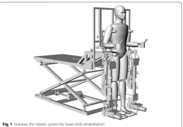
The aim of the present study is to develop a myoelectric control (MEC) algorithm, based on the algorithm proposed by Hayashi et al. [19], but that does not require addi-tional sensors and uses the maximum voluntary contraction (MVC) as a simple cali-bration process. The sEMG signal processing algorithm can detect the orientation and approximate the intensity of movement intention proportionally to the maximum MVC tests. The proposed MEC algorithm was implemented in a computational model of the lower limb rehabilitation system, Nukawa. Such a mechatronic system is a product of requirements presented by an interdisciplinary group, formed by physiotherapist and engineers, and has its antecedents in [25]. The mechanical design, presented in Fig. 1, consists of two limbs, each one composed by a three-link mechanism and a Computed Torque Control (CTC). The implementation of the CTC algorithm was conducted in a first stage as a hardware-in-the-loop (HIL), using the Nukawa simulation model without having to use the actual robot since Nukawa is not yet fully operational [26].
The three degrees of freedom allows each leg to perform flexion/extension (FE) move-ments of the hip, FE movemove-ments of the knee, and dorsi/plantar (DP) flexion movemove-ments of the ankle [25]. The design also has three brushless motors in each limb, power drivers, and encoders.
The joints are, approximately, collinear to human joints, and the system allows to adjust the length of each segment. The knee of the human body is a polycentric joint.
(1)
However, a simplification was conducted, as presented by Zoss et al. [27], where a pure rotational joint in the sagittal plane was proposed for the exoskeleton. The system was designed for people from 1.44 to 1.85 m and up to 85 kg weight. The ROM of each joint was restricted with mechanicals stops considering the ROM for hip, knee, and ankle.
The MEC was conducted using a simulated model of Nukawa instead of the actual robot. Moreover, the sEMG signal processing algorithm and the movement control algo-rithm were implemented and tested with the simulated model, using an HIL simulation. The tests were conducted extracting signals from a sEMG signals collection, leading them into the real-time algorithms, and finally controlling the computational model of Nukawa.
The proposed MEC algorithm employs an estimated movement intention value of the knee joint. This estimation is mapped to the desired speed of the knee joint employing scal-ing factors. Such a speed is the input to the CTC algorithm of the simulated robotic system.
Methods
This section presents the methodology used in the development of a sEMG signal pro-cessing algorithm to assess the detection of intended movement, based on the algorithm proposed by Hayashi et al. [19]. The algorithm was developed in both the offline pro-gramming environment MATLAB and as an HIL simulation in Python within a Beagle Bone Black (BBB) Rev C, which is a development platform.
sEMG signal processing
This section proposes a sEMG signal processing algorithm, based on the algorithm stated by Hayashi et al. [19], to assess the detection of movement intention. The pro-posed sEMG signal processing algorithm can detect, approximately, the intensity of
the motion intention proportionally facing the MVC. In this section, the signal pro-cessing algorithm was not conducted in real-time. However, tests were carried out with pre-recorded signals as proposed in the simulation-based methodology, stated by some of the authors in [28, 29].
Figures 2, 3 and 4 present the block diagrams that make up the sEMG signal process-ing algorithm. In these figures the notation [n×m] is the size of the signal bus, where n
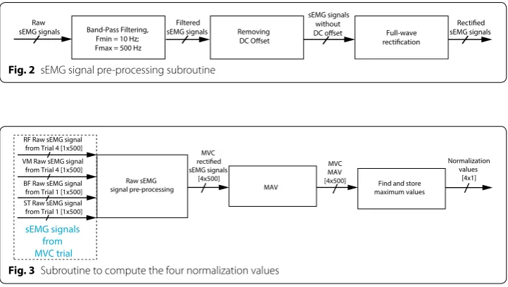
is the number of signals and m is the number of samples in the observation window. Figure 2 presents a block diagram containing the principal functions of the sEMG signal pre-processing subroutine. In this figure it is possible to notice that the algo-rithm has three main blocks which are (1) band-pass filtering, (2) removing DC offset, and (3) full-wave rectification. This subroutine starts filtering the raw sEMG signals. A band-pass Butterworth filter with cut-off frequencies of 10 Hz and 500 Hz was used. A Notch filter was not used, since scientific recommendations from the SENIAM and the ISEK reports that EMG recordings should not use any notch filter [30, 31].
Besides, the mean of the sEMG signals is subtracted, to remove the DC offset. Sub-sequently, the subroutine performs full-wave rectification of the signals, computing the absolute value. The full-wave rectification process is conducted so that amplitude parameters such as the MAV or RMS can be applied to sEMG signals [32].
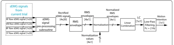
Figure 3 presents a block diagram containing the principal functions of the subroutine to compute four normalization values. In this figure it is possible to notice that the algo-rithm has three main blocks which are (1) raw sEMG signal pre-processing subroutine presented in Fig. 2, (2) MAV, and (3) finding and storing maximum values. The subrou-tine presented in Fig. 3 uses RF and VM signals, from Trial 4, and BF and ST signals, from Trial 1, to compute four normalization values, i.e., the MVC tests. These signals are later used to normalize the signals of these muscles, respectively. In the four cases, the algorithm extracts the MAV using adjacent windows of 500 ms, later the algorithm finds the maximum MAV, and it stores the maximum value obtained for each signal.
Band-Pass Filtering, Fmin = 10 Hz; Fmax = 500 Hz
Removing Full-wave Filtered
sEMG signals
sEMG signals without
sEMG signals Raw
sEMG signals
Fig. 2 sEMG signal pre-processing subroutine
RF Raw sEMG signal from Trial 4 [1x500]
MAV VM Raw sEMG signal
from Trial 4 [1x500] MAV MVC
[4x500] Find and store maximum values
Normalization values
[4x1] Raw sEMG
signal pre-processing BF Raw sEMG signal
from Trial 1 [1x500] ST Raw sEMG signal from Trial 1 [1x500]
MVC
sEMG signals [4x500]
sEMG signals from MVC trial
Motion intention algorithm
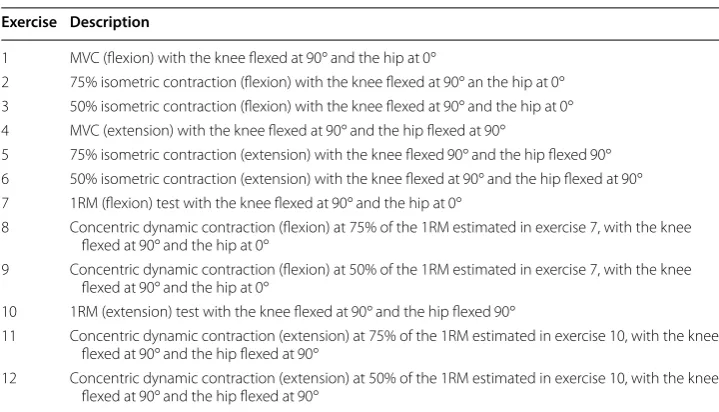
Figure 4 presents a block diagram containing the principal functions of the main rou-tine of the motion intention algorithm. In this figure it is possible to notice that the algorithm has five main blocks which are (1) sEMG signal pre-processing subroutine presented in Fig. 2, (2) RMS envelope, (3) normalization, (4) linear combination, and (5) low-pass filtering.
The main routine uses the four raw sEMG signals from the RF, VM, BF, and ST of current exercise and conducts them to the sEMG signal pre-processing subroutine. Subsequently, the algorithm extracts an RMS envelope of the four channels with sliding adjacent 20 ms windows since the algorithm should be fast and light, i.e., the total num-ber of samples in a window from the vector of the signal was 20 samples. Afterward, the signals are normalized using the values previously stored for each of the channels during the MVC exercises, as previously mentioned in subroutine presented in Fig. 3. These sig-nals are denoted as RFRMS , VMRMS , BFRMS , and STRMS , which are the normalized RMS envelopes.
Finally, to detect the movement intention, a linear combination LC∈R of the four
RMS envelopes is proposed, i.e., the features of four channels were combined. This LC
is based on the algorithm proposed by Hayashi et al. [19], in which two channels were used. However, the conversion coefficients ae∈R , af ∈R , be∈R , and bf ∈R are not
estimated with an additional torque sensor, as proposed by Hayashi et al. [19], but deter-mined heuristically. Moreover, the LC proposed in this paper uses four sEMG channels instead of two. To do so, the equation
was proposed, where RFRMS∈R , VMRMS∈R , BFRMS∈R , and STRMS∈R are the
nor-malized RMS envelopes of the RF, VM, BF, and ST, respectively, taking into account that the RF and the VM muscles activate more during an extension intention. Moreover, the RMS envelope of these channels would be greater than the RMS envelope of the BF and the ST muscles during an extension intention. Therefore, the conversion coefficients of the RFRMS and the VMRMS have a positive sign, i.e., aRF =1 , bRF =0 , aVM=1 , and bVM=0 . The BF and the ST muscles activate more during a flexion intention. Therefore, the conversion coefficients of the BFRMS and the STRMS are negative, since that these muscles are opposed to the RF and the VM muscles, i.e., aBF = −1 , bBF =0 , aST = −1 , and bST =0 . Therefore, when the subject intends to perform a knee flexion, the LC is negative in a comparable way to the MVC exercise for the flexion, and when the sub-ject intends to carry out a knee extension, the LC is positive proportionally to the MVC
(2)
LC=RFRMS+VMRMS−BFRMS−STRMS sEMG
signal pre-processing
subroutine
Normalization CombinationLinear Low-Pass Filtering, Fc = 2 Hz sEMG signals
[4x20] RMS envelope
Normalized RMS envelopes
[4x1]
VM Raw sEMG signal [1x20] BF Raw sEMG signal [1x20]
ST Raw sEMG signal [1x20]
Normalization values
[4x1] RMS envelopes
[4x1] [1x1]LC IntentionMotion [1x1]
RF Raw sEMG signal [1x20] sEMG signals
from current trial
exercise for the extension. Therefore, the motion intention of the proposed LC algorithm is a continuous value between − 2 and 2, i.e., LC∈[−2, 2] , where − 2 and 2 are achieved during the MVC exercises in flexion and extension, respectively. Finally, the LC was fil-tered using a low-pass digital Butterworth Filter with a cut-off frequency of 2 Hz, order one, to remove the peaks and smooth the signal.
Myoelectric control
This section shows how the motion intention algorithm presented before and the movement control algorithm, based on a Computed Torque Control (CTC) algorithm reported by the authors in a previous publication [26], were joined as an HIL simulation to create the MEC algorithm.
The protocol of the tests was carried out in real-time conducting the pre-recorded sEMG signals to the MEC algorithm. These signals correspond to those of the exer-cises mentioned in Table 1, specifically exercises 7–9, which correspond to concen-tric dynamic contraction of flexion and exercises 10–12 that correspond to concenconcen-tric dynamic contraction of extension exercises. The tests assessed if the movement devel-oped by the robotic system corresponds to the movement intention executed by the subject during the experimental protocol. Therefore, the tests did not involve individ-uals or animals but pre-recorded signals using a custom-made sEMG signal simulator. A four component architecture was used to conduct the protocol of tests. The cus-tom-made sEMG signal simulator is the first element. The simulator was developed in Python, a high-level programming language. The custom-made sEMG signal simula-tor extracts the signals from the computer and sends them from a computer to the BBB. The computer used for the tests was an IntelCoreTM i5 with a 4 GB DD3 mem-ory RAM. The computer communicates with the BBB through TCP/IP within a pre-defined communication port. The sampling period was set to TS=0.02 s . Therefore, the signals were extracted using a 20 ms window each time. The portion of the sEMG signals was conducted to the second component. A real-time implementation of the
Table 1 Exercises conducted during the experimental protocol Exercise Description
1 MVC (flexion) with the knee flexed at 90◦ and the hip at 0◦
2 75% isometric contraction (flexion) with the knee flexed at 90◦ an the hip at 0◦ 3 50% isometric contraction (flexion) with the knee flexed at 90◦ and the hip at 0◦ 4 MVC (extension) with the knee flexed at 90◦ and the hip flexed at 90◦
5 75% isometric contraction (extension) with the knee flexed 90◦ and the hip flexed 90◦ 6 50% isometric contraction (extension) with the knee flexed at 90◦ and the hip flexed at 90◦ 7 1RM (flexion) test with the knee flexed at 90◦ and the hip at 0◦
8 Concentric dynamic contraction (flexion) at 75% of the 1RM estimated in exercise 7, with the knee flexed at 90◦ and the hip at 0◦
9 Concentric dynamic contraction (flexion) at 50% of the 1RM estimated in exercise 7, with the knee flexed at 90◦ and the hip at 0◦
10 1RM (extension) test with the knee flexed at 90◦ and the hip flexed 90◦
11 Concentric dynamic contraction (extension) at 75% of the 1RM estimated in exercise 10, with the knee flexed at 90◦ and the hip flexed at 90◦
sEMG signal processing algorithm presented in Section Motion intention algorithm is the second component. The sEMG signal processing algorithm was implemented in real-time in a BBB which has an AM335x 1 GHz ARMCortex-A8 processor and a 512 MB DDR3 Memory RAM. This implementation was also conducted using Python. The sEMG signal processing algorithm was developed in real-time as an HIL simula-tion, i.e., tests were performed using pre-recorded signals. Moreover, tests were car-ried out as proposed in the simulation-based methodology stated by the authors in [28, 29].
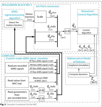
The motion intention was sent through TCP/IP to the third component, which was the movement control algorithm presented by the authors in [26], and was also located in the BBB. To do so, a set-point conversion is conducted as shown in Fig. 5, i.e., the output of the motion intention algorithm LC is scaled taking into account that
where q˙dKnee∈R is the desired speed for the knee joint, α∈R is the amplitude
scal-ing factor, and β∈R is the offset, two parameters left to the physiotherapist’s choice,
according to the exercise. Subsequently, qdHip∈R and qdAnkle∈R are derived, which
are the desired angles given by the goniometers for hip and ankle joints, respectively.
(3)
˙
qdKnee=αLC+β,
Therefore, q˙dHip∈R and ˙qdAnkle∈R , the desired speed for the hip and ankle joints are obtained, respectively. In Fig. 5, the notation [n×m] is the size of the signal bus where n is the number of signals, and m is the number of samples in the observation window. The movement control algorithm is responsible for computing the torque τu∈R3×1 . The calculated torque τu is sent back to the computer through TCP/IP, to the fourth component, which is the mathematical model of Nukawa presented by the authors in [26].
The simulation of the dynamics of Nukawa is performed in the computer, in MAT-LAB, computing qm∈R3×1 , q˙m∈R3×1 , and q¨m∈R3×1 which represent the joint meas-ured positions, velocities, and accelerations, respectively, i.e., after the simulation of the dynamics. Therefore, the graphic model moves as the desired path indicate it. Finally, an acknowledgment was sent back, and the loop was repeated each sampling period.
In order to validate that the MEC algorithm works correctly during actual exercises for rehabilitation of ACL injuries, six tests were conducted using the six dynamic exercises presented before, i.e., exercises 7–12. The graphic and numerical results of the six tests are shown below. These tests were carried out randomly, i.e., the combi-nation of subject and exercise was randomized.
Experiments and results
The tests of the algorithm were conducted in the offline programming environment MATLAB and as an HIL simulation in Python within a BBB Rev C. sEMG and kinematic signals of healthy subjects were obtained to test the algorithm. Finally, a test protocol was conducted to assess the behavior of the MEC algorithm for robot-assisted rehabili-tation and its possibilities to aid rehabilirehabili-tation therapies for ACL injuries.
Subjects
An experimental protocol with 17 healthy subjects was conducted to record sEMG sig-nals and its corresponding kinematics associated with rehabilitation body movements for ACL injuries. The ethics committee approved these tests.
Before each test all participants were deemed healthy under a clinical evaluation car-ried out by a health professional. Body weight, body height, blood pressure, heart rate, respiration rate, and body temperature were measured. Therefore, all of them were accepted in the study. The tests also recorded the age, suprapatellar perimeter, calf perimeter, inter-joint hip/knee distance, and inter-joint knee/ankle distance. The age of participants ranged from 19 to 47 years, with a median (interquartile range) of 25.5 years (23–30.5 years). Moreover, the body weight ranged from 50.1 to 81.9 kg and the body height ranged from 1.46 to 1.85 m . In addition, the inter-joint hip/knee distance ranged from 0.35 to 0.44 m and the inter-joint knee/ankle distance ranged from 0.35 to 0.47 m.
Signal acquisition
configured to fs=1 kHz . The sensed data was stored using the OpenSignals software (Plux, Lisbon, Portugal). In order to capture the movements performed by the subjects during the selected experimental protocol, three twin axis goniometers (SG150) were used (Biometrics Ltd, Newport, UK). However, the tests only used the FE channels of each goniometer to measure hip FE movements, knee FE movements, and ankle DP flex-ion movements. The goniometers were located in the subject’s dominant lower limb. The location of the goniometers was conducted following some of the recommendations of the goniometer and torsiometer operating manual from Biometrics Ltd [33].
The sEMG sensor placement was determined based on some of the recommendations of the SENIAM Project [31]. According to the ISEK Standards for Reporting EMG Data [30] the characteristics of the procedure are shown:
The raw signal was detected using four pairs of commercial, disposable and adhesive gel surface electrodes placed in different parts of the upper leg of a group of healthy subjects, along with a reference electrode. The electrodes had a disc shape and were made of Ag/ AgCl. They were placed with an interelectrode distance of approximately 3.5 cm , center point to center point. The skin of fourteen subjects was shaved, and three subjects were not shaved. The area of interest was cleaned with alcohol before placing the electrodes to reduce the impedance between the electrodes and the skin. The electrodes were placed in order to detect flexion and extension of the knee, i.e., Rectus Femoris (RF), and Vastus Medialis (VM) muscles, detecting activation when the knee joint was extended, and Biceps Femoris (BF) and Semitendinosus (ST) muscles, detecting activation when the knee joint was flexed.
The electrodes were fixed parallel to the muscle fiber direction using the dominant middle portion of the muscle belly for best selectivity and avoiding the region of motor points. The signals were acquired using the Biosignalsplux. The device has a differential configuration, an input impedance of 100 G , CMRR of 100 dB, and it was configured with a gain of 1000. The biosignals were sampled at 1 kHz. The reference electrode was located on the Processus Spinosus of C7, in an electrically unaffected area.
To acquire the sEMG signals regarding ACL rehabilitation exercises, 12 exercises were conducted with each subject. Table 1 presents a description of the 12 exercises that were selected with the assistance of a physiotherapist with a graduate certificate in Biomedical Engineering. The test took approximately 2 h with each participant.
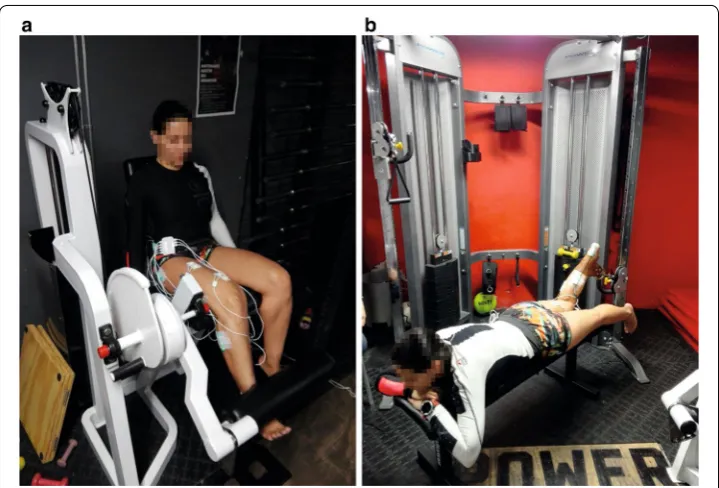
The physiotherapist selected six isometric exercises (1–6) and six concentric dynamic contraction exercises (7–12). Figure 6 presents two gym machines that were used during the experimental protocol for these two types of exercises. Figure 6a and b present the leg extension machine and the crossover machine, respectively.
The concentric dynamic contraction exercises were conducted taking into account the one-repetition-maximum (1RM) test. This test evaluates the maximum weight that an individual can lift only once for an exercise. Conducting the 1RM test may be contrain-dicated for some populations with preexisting medical conditions. Therefore, several 1RM strength prediction equations have been proposed, i.e., the 1RM can be predicted lifting the greatest weight possible for a certain number of repetitions, until fatigue [34,
35]. Some of the formulas were proposed by Lander [36], Brzycki [37], O’Connor et al. [38], and Epley [39]. Epley proposed that
(4)
1RM=w
1+ r 30
where w represents the weight lifted by the subject and r is the number of repetitions executed, until fatigue. Equation (4) is widely employed due to its ease of use.
Results of the offline implementation
The tests of the sEMG signal processing algorithm were conducted with the signals acquired from the 17 healthy subjects. However, to exemplify the algorithm, the imple-mentation with the signals obtained during the tests with the fifth subject (S5) is pre-sented below (randomly selected). Figure 7 presents the results of the LC in light gray,
Fig. 6 Gym machines used during the experimental protocol: a leg extension machine and b crossover machine
0 1 2 3 4 5 6 7
Time (s)
0 0.5 1 1.5 2 2.5
Normalized amplitud
e
Linear Combination Filtered Linear Combination
and the LC filtered in black. In this figure, it can be observed the detection of the sub-ject’s intention to perform an extension movement, since the LC filtered has a positive sign.
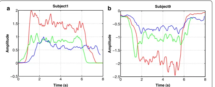
Figure 8a presents the results of conducting the signals of all three isometric exten-sion exercises (4–6) from subject 1 to the motion intention algorithm. Figure 8b presents the results of conducting the signals of all three isometric flexion exercises (1–3) from subject 6 to the motion intention algorithm. Each subfigure has three lines, one for exer-cise. The red, green, and blue lines represent the detection of the motion intention LC
for the MVC test, 75% isometric contraction, and 50% isometric contraction exercises, respectively.
Graphic results of the protocol of tests
With the purpose of exemplifying the behavior of the MEC, the implementation with the signals obtained during exercise 9 with the seventh subject (S7) is presented below.
Figure 9a–d presents the result of an HIL simulation for exercise 9 with S7. During exercise 9, the subject was prone on a flat bench with the knee flexed 90◦ , hip at 0◦ . Their ankle was fastened with a belt to a crossover machine. However, the simulations were conducted with the subject in a supine position, since Nukawa is not designed to per-form therapies in a prone position. The above is acceptable for rehabilitation purposes since the exercises were selected taking into account international protocols for rehabili-tation of ACL injuries, as presented in “Signal acquisition” section.
The online simulation presented in Fig. 9a was conducted using a 3D CAD model of Nukawa. This simulation included the kinematics of the robot. The simplified model of the robot was used as well, to reduce the computational time of the real-time tests. Figure 9b presents the result of the HIL simulation with the simplified model. In both figures, the red and dotted line represents the actual endpoint of the robot, i.e., the distal point of the third limb. In Fig. 9c presents the desired speed in a continuous line and the actual speed in a dotted line. In this figure, it is possible to observe that the system can follow the desired speed, i.e., the motion intention since both have similar
0 2 4 6 8
−0.5 0 0.5 1 1.5
2 Subject1
Amplitude
Time (s)
0 2 4 6 8
−2.5 −2 −1.5 −1 −0.5
0 Subject9
Amplitude
Time (s)
a b
behavior. Also, it can be denoted that the system follows the imposed set-point visu-alizing the error presented in Fig. 9d.
Numerical results of the protocol of tests
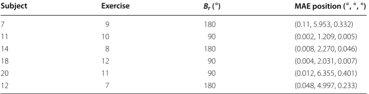
The numerical results of the behavior of the MEC algorithm are shown in Table 2, which presents the trajectory tracking mean absolute error (MAE) of the control algorithm which was commanded with a set-point of q˙dKnee . As indicated in the table, the maxi-mum position MAE is 0.1◦ , 6.3◦ , and 0.3◦ for the hip, knee, and ankle joints, respectively. Thus, the error is lowest in the knee.
−1 −0.5 0 0.5 1 −1
−0.5 0 0.5 1
Sagittal plane (XZ). Schematic of Nukawa Exosqueleton
X Axis (m)
Z Axis (m
)
0 0.5 1 1.5 2 2.5 3
−10 −5 0
5 Hip
Angle
(
/s) Desired speed
Actual speed
0 0.5 1 1.5 2 2.5 3 −200
0 200
400 Knee
Angle
(
/s) Desired speed
Actual speed
0 0.5 1 1.5 2 2.5 3 −10
0 10
20 Ankle
Time (s)
Angle
(
/s) Desired speed
Actual speed
0 0.5 1 1.5 2 2.5 3 −5
0 5
10 Hip
Angle
(
/s) Speed error
0 0.5 1 1.5 2 2.5 3 −100
0 100
200 Knee
Angle
(
/s) Speed error
0 0.5 1 1.5 2 2.5 3 −20
−10 0
10 Ankle
Time (s)
Angle
(
/s) Speed error
a b
c d
Fig. 9 Results of the HIL simulation using a trajectory extracted during exercise 9 with S7 a 3D simulation, b
simplified simulation, c desired speed vs. actual speed, and d speed error
Table 2 Trajectory tracking error of the control algorithm which was commanded with a set-point of q˙dKnee
Subject Exercise Br ( ◦) MAE position ( ◦ , ◦ , ◦)
7 9 180 (0.11, 5.953, 0.332)
11 10 90 (0.002, 1.209, 0.005)
14 8 180 (0.008, 2.270, 0.046)
18 12 90 (0.004, 2.031, 0.007)
20 11 90 (0.012, 6.355, 0.401)
For the above, the contribution of the MEC algorithm was validated for the implemen-tation of robot-assisted rehabiliimplemen-tation of ACL injuries. During these therapies, the MEC algorithm would detect when the subject tries to move the knee, but due to the pain caused by the ACL injury, the patient is not able to execute the motion. Therefore, the MEC algorithm would assist its movement using the robotic system.
Discussion
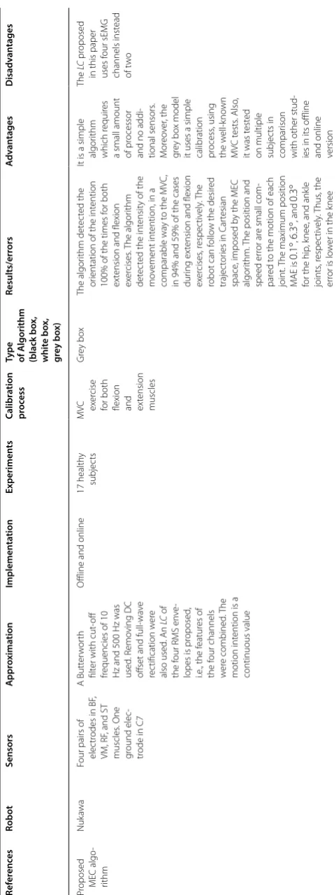
The novelty of the MEC algorithm proposed in this paper has two relevant character-istics. The first one is a simplified sEMG signal processing algorithm, to detect move-ment intention, that only requires an MVC test for calibration, i.e., it does not require additional sensors. The second one is that the motion intention was mapped to a speed set-point instead of a position or torque set-point, as is usually reported in the literature. A wider explanation of both characteristics is presented below.
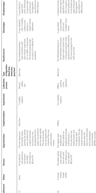
To expand the information of the first characteristic, it is important to mention that some of the algorithms reported in the literature use a machine learning algorithm for the motion intention detection [17, 23, 40, 41]. Moreover, other algorithms use a model-based approach [22, 24, 42, 43]. However, those algorithms are more complex than the one reported in this paper. Therefore, they need more computing power. In the case of the proposed MEC algorithm, a simplified sEMG motion intention detection approach was achieved, similar to the ones proposed by [19–21]. The simplicity of the proposed algorithm makes it different from several approaches reported in the literature, where Artificial Neural Networks (ANN), Support Vector Machines (SVM), Hill-type mus-cular models, among others are used. This simplicity makes it easy to implement the algorithm in real-time. In comparison with other approaches that use machine learn-ing algorithms, it is not necessary to perform high computational processes. A simple MVC calibration process is enough. The MVC test is used in most sEMG investigations to normalize the signals. Additionally, the proposed MEC algorithm requires no data sets, as the machine learning algorithms reported by other authors [40, 41, 44]. Since the sEMG signal is changing each session, it would be necessary to capture the MVC signal every time the algorithm is used, i.e., it requires an MVC exercise to obtain the calibration values for each session to process and detect the motion intention with EMG signals. Therefore, the MVC test may be conducted each time that the subject wears the robotic system to perform the simple calibration process. The information coming from sEMG signals was enough to detect the subject’s intention. No extra sensors, in addi-tion to the sEMG electrodes, are required for the proposed MEC algorithm to work. Other approaches require additional sensors such as accelerometers, encoders, torque meter, goniometers, among others [17, 42, 45–47]. Additional sensors have the disad-vantage that they deliver information about the intention after sEMG sensors and add extra costs. sEMG signals allow having an a priori estimation of the subject’s intention since sEMG signals appear before the muscle contraction is generated, i.e., the so-called electromechanical delay (EMD) [45].
interaction torque, however, the proposed MEC algorithm detects the intention and ori-entation of the intention. This information is enough in the application for the robotic system Nukawa and can be useful for other areas such as biofeedback or interaction with robotic systems. Table 3 presents a comprehensive comparison with other sEMG motion intention algorithms. According to the results, an approximation of the intensity through a simplified algorithm was obtained despite not being the objective pursued. In this case, the intensity is unitless and is proportional to the MVC. The assumption is that, as reported in the state of the art if the coefficients of the LC were identified by the calibration process with additional torque sensors, the algorithm would estimate the torque.
Some limitations of this study are: The proposed algorithm was tested on both offline and online. However, the results cannot be generalized to the entire population, only to the sample, i.e., the study population is not statistically significant to generalize the results. Also, as the tests were performed on healthy subjects, it is still not possible to conclude about the behavior of the MEC algorithm with sEMG signals from subjects with ACL injuries. Therefore, the results obtained cannot be extrapolated directly to people with this type of injury. This restriction also applies to all approaches reported in the literature that conducted the tests with healthy subjects where the extension to other conditions must be proven. Also, the experimental protocol did not consider to measure or control the factors that affect the sEMG signals, e.g., the environmental temperature, the body temperature, the skin impedance and location of the electrodes. Therefore, it is not feasible to conclude if the proposed MEC algorithm is affected by these factors.
Finally, CTC is a model-based control which enables compliant robot control with small tracking errors for accurate robot models. Nevertheless, the proposed MEC algo-rithm was tested only with this controller. Therefore, future work includes several tests to the MEC algorithm with other control algorithms to assess the robustness.
Conclusions
Surface electromyography (sEMG) signal processing algorithm, based on the algorithm reported by Hayashi et al. in [19], was proposed. The proposed algorithm detects the motion intention in the knee joint and requires no prior training with sEMG signals from other subjects. Moreover, no additional torque sensor is required to estimate the conversion coefficients from the Linear Combination (LC) algorithm.
The results showed that when a subject intended to perform a knee flexion or exten-sion, without executing the movement, the algorithm detected the orientation of the movement intention. Moreover, when a subject intended to carry out an exten-sion movement, the algorithm detected an LC with a positive sign, and when a subject intended to perform a flexion movement, the algorithm detected an LC with a negative sign.
Table 3 A c ompr ehensiv e c
omparison with other sEMG motion in
ten tion algorithms Ref er enc es Robot Sensors A ppr oxima tion Implemen ta tion Experimen ts Calibr ation pr oc ess
Type of A
lgorithm (black bo x, whit e bo x, gr ey bo x) Results/err ors A dv an tages D isadv an tages Pr
oposed MEC algo
-rithm
Nuk
awa
Four pairs of elec
tr
odes in BF
,
VM, RF
, and ST
muscles . One gr ound elec -tr
ode in C7
A Butt er w or th filt
er with cut
-off
frequencies of 10 Hz and 500 H
z was used . R emo ving DC off
set and
full-wa ve rec tification w er e also used . An LC of the f
our RMS en
ve
-lopes is pr
oposed
,
i.e
., the f
eatur es of the f our channels w er e combined . T he motion int
ention is a
continuous value
O
ffline and online
17 health
y
subjec
ts
MV
C exer
cise
for both flexion and extension muscles
Gr ey bo x The algor ithm det ec ted the or
ientation of the int
ention
100% of the times f
or both
ex
tension and flexion
ex er cises . T he algor ithm det ec
ted the int
ensit
y of the
mo
vement int
ention, in a
comparable wa
y t
o the MV
C,
in 94% and 59% of the cases dur
ing ex
tension and flexion
ex er cises , r espec tiv ely . T he
robot can f
ollo
w the desir
ed
trajec
tor
ies in C
ar
tesian
space
, imposed b
y the MEC
algor
ithm.
The position and
speed er
ror ar
e small com
-par
ed t
o the motion of each
joint.
The maximum position
M
AE is
0.1
◦ ,
6.3
◦ , and
0.3
◦
for the hip
, k
nee
, and ank
le joints , r espec tiv ely . T hus , the er
ror is lo
w
er in the k
nee
It is a simple algor
ithm
which r
equir
es
a small amount of pr
ocessor
and no addi
-tional sensors . M or eo ver , the gr ey bo x model
it uses a simple calibration process
, using the w ell-k no wn MV C t ests . Also ,
it was t
est
ed
on multiple subjec
ts in
compar
ison
with other stud
-ies in its offline and online version
The
LC
pr
oposed
in this paper uses f
Table 3 (c on tinued) Ref er enc es Robot Sensors A ppr oxima tion Implemen ta tion Experimen ts Calibr ation pr oc ess
Type of A
lgorithm (black bo x, whit e bo x, gr ey bo x) Results/err ors A dv an tages D isadv an tages [ 17 ] None An acceler om -et
er placed on
the f
or
ear
m
and sEMG elec
tr odes on BB and TB The ra w sig nal was pr ocessed . Subse -quently
, the sig
nals w er e r ec tified , and a sig nal nor maliza -tion pr ocess was de veloped f or each subjec t accor ding t o pr e-r ecor ded sig nals .
The neural ac
tivit y was calculat ed , and a K alman F ilt er was used t o pr edic t motion Real-time 12 health y subjec ts M
anual calibra
-tion
Black bo
x
The model pr
esent ed a high cor relation with slo w-motion trajec tor ies (CC = 0.999–1). M or eo ver , the r esults sho w ed high accurac
y (97.4–98.6%) of
pr
edic
tion
It was validat
ed
with 12 health
y
subjec
ts and
requir
es a
simple manual calibration
It was t
est
ed on
upper limb joints
. M or eo ver , it r equir es addi -tional sensors . The algor ithm was t est
ed in an
offline fashion [ 18 ] A vir tual
human model (VHM)
The sEMG sig
nals
w
er
e collec
ted
from the ant
e-rior delt oid , pos -ter ior delt oid , BB
, and TB
The sig nals w er e rec tified with RMS t
o obtain an
amplitude en velope . Subsequently , a lo
w pass filt
er was implement ed , and the sig nals w er e nor maliz ed . T he ra w and pr e-pr ocessed sig nals w er e the
input of a thr
ee -la yer back pr opagation neural net w or k (BPNN) contr oller O ffline Four health y subjec ts O
ffline training of the algor
ithm
Black bo
x
The ANN per
for
mance in
the estimation of the joint angle in each motion was comput
ed using the mean
squar
ed er
ror (MSE) method
.
The w
orst a
verage f
or the
MSE was 0.239
It was t
est
ed
using multiple joints and multiple mo
ve -ments It r equir es t
o train a
machine lear ning algor ithm. T her e-for
e, it r
equir
es a
training data set, It was t
est
ed on
upper limb joints
.
The algor
ithm
was t
est
ed in an
Table 3 (c on tinued) Ref er enc es Robot Sensors A ppr oxima tion Implemen ta tion Experimen ts Calibr ation pr oc ess
Type of A
lgorithm (black bo x, whit e bo x, gr ey bo x) Results/err ors A dv an tages D isadv an tages [ 19 ] HAL -3 Tw
o sensors near the flex
or and ex tensor muscles Sig nals w er e filt er ed and amplified , and the m yoelec tr ic ac tivit
y was com
-put
ed f
or both chan
-nels . Subsequently , the estimat ed muscle t or que was comput
ed as a
linear combination of both, tak
ing int
o
account the equa
-tion of a straight line
.
Finally
, a gain param
-et
er was used t
o
comput
e the t
or
que
for the ac
tuat or Online A health y subjec t A calibra
-tion process is necessar
y
to obtain the con
-version coeffi
-cients Black bo x The con version coefficients
depend on the sensor location and the operat
or
’s
ph
ysical condition
It uses a simple algor
ithm, and
it was t
est
ed
online in a com
-mer cial r obotic ex osk elet on It r equir
es a long
calibration pr
o-cess
, including
additional sensors such as t
or que sensors [ 20 ] A comput er
model of the index finger and wrist joints
Flex
or dig
itorum
super
ficialis
(FDS) and flex
or
car
pi ulnar
is
(FCU)
An RMS en
velope was comput ed . Subse -quently
, a lo
w-pass
filt
er was used
, and tw o diff er ent func -tions w er
e used f
or
the finger position
Online 18 health y subjec t Simple cali
-bration process of constants
Black bo
x
The maximum er
rors obtained
w
er
e
3.77
◦ . A dir
ec t r elation -ship bet w
een the RMS and
the motion of model was obser
ved
It uses a simple algor
ithm, and
it was t
est
ed
in an online fashion. I
t
requir
es a sim
-ple calibration process
, and
it was t
est
ed
on 18 health
y
subjec
ts
It was t
est
ed on
Table 3 (c on tinued) Ref er enc es Robot Sensors A ppr oxima tion Implemen ta tion Experimen ts Calibr ation pr oc ess
Type of A
lgorithm (black bo x, whit e bo x, gr ey bo x) Results/err ors A dv an tages D isadv an tages [ 21 ] NEUR O -ex os BB and TB
The EMG sig
nals w
er
e
pr
ocessed obtaining
a linear en
velope (LE) thr ough full-wa ve r ec tification. Both sig nals w er e conduc ted t o a pr opor tional con -tr oller t o manipulat e
the flexion and extension of the exosk
elet on Online Ten health y subjec ts Subjec ts selec ted
the gains of the algor
ithm
in a previous proce
-dur e Black bo x Subjec
ts could fulfill the
tasks dur
ing all tr
ials
, no
matt
er the per
centage of assistance , ex tra w eight or mo vement pace It r equir es a simple calibra -tion ex er cise ,
it was t
est
ed
in an online fashion, and it was t
est ed on t en health y subjec ts
It was t
est
ed on
upper limb joints
[ 23 ] None BB and TB The M
AV was com
-put ed . Subse -quently , discr iminant
analysis and an SVM was used t
o classify the sig nals Not r epor ted Thr ee health y subjec ts
Training of the algo
-rithm Black bo x Classification accurac y f or the discr
iminant analysis and
the SVM was 96% and 99%, respec
tiv
ely
It was t
est
ed
using multiple joints and multiple mo
ve -ments It r equir es t
o train a
machine lear ning algor ithm. T her e-for
e, it r
equir
es
a training data set, it was t
est
ed
on upper limb joints
. T
he t
ype of
implementation is not r
epor ted [ 24 ] None BB and TB A lo w-pass filt er was used . Subsequently , tw o time -domain featur es w er e ex trac
ted and the
sig nals w er e nor mal -iz ed
. A linear stat
e-space model was used t
o estimat e joint motion O ffline Tw o health y subjec ts at tw o load le vels O
ffline training of the algor
ithm
Black bo
x
The authors obtained a r
oot -mean-squar e er ror rang ing bet w
een 8.3 and 10.6%.
Also
, the pr
edic
tion er
ror
of the a
verage angle was
ar ound 10% It o ver comes subjec t-specific pr oblems
It was t
est
ed in an
offline fashion. It was t
est
ed on
upper limb joints and just in t
w
o
subjec
Table 3 (c on tinued) Ref er enc es Robot Sensors A ppr oxima tion Implemen ta tion Experimen ts Calibr ation pr oc ess
Type of A
lgorithm (black bo x, whit e bo x, gr ey bo x) Results/err ors A dv an tages D isadv an tages [ 41 ] iL eg RF
, VL, VM,
BF and ST Full wa ve r ec tification, lo
w pass filt
er of
2 H
z of the sEMG
sig
nals which ar
e
inputs of a net
w or k Neural net w or k. T he
angle and speed ar
e
also inputs t
o the neural net w or k O ffline One health y subjec t
Training the neural net
w or k Black bo x The r oot -mean-squar e er ror
is 0.67 N
m f
or hip t
or
que
estimation and 0.37 N
m f
or
knee t
or
que estimation
It can be used to per
for m a real-time coor -dinat ed ac tiv e
training with a rehabilitation robot. I
t was test ed using multiple joints , hip
, and k
nee The pr oposed appr oach was test
ed with a
cir cular -lik e tra -jec tor y. R equir es
additional sensors to measur
e
angular position and speed
[ 43 ] A ctuat ed leg-or thosis syst em
VL, RF and ST muscles
The sEMG sig
nals w er e full wa ve r ec tified . Subsequently , a lo
w pass filt
er was used . F inally , the pr ocessed sig nals w er
e used as inputs
of a H
ill-t ype muscle model Online One health y subjec t The exper
i-mental torque was com
-put ed b y emplo
y-ing the inverse dynamics
Whit
e bo
x
Fr
om the exper
imental r
esults
the authors obtained a calibration accurac
y with
an RMSE rang
ing bet
w
een
1.49 and 1.99 N
m and the
av
erage R2 was 0.89
The calibration pr
ocess is subjec t-specific . The algor ithm
uses a whit
e-bo x model , which mak es
it easier t
o understand . I t was t est
ed in an
online fashion
The model r
equir es kno wing param -et
ers such as the
lengths of the muscles in
volv
ed
.
Table 3 (c on tinued) Ref er enc es Robot Sensors A ppr oxima tion Implemen ta tion Experimen ts Calibr ation pr oc ess
Type of A
lgorithm (black bo x, whit e bo x, gr ey bo x) Results/err ors A dv an tages D isadv an tages [ 44 ] None M
uscles of the quadr
iceps A daptiv e neural net w or
ks and fuzz
y log ic O ffline One Health y subjec t
Training the neural net
w
or
k
and set the infer
ence
rules of the fuzz
y log ic Black bo x The per for
mance of the
algor
ithm af
ter least squar
e
reached the desir
ed t
or
que
le
vel with a mean squar
e
er
ror of 181.8
This model uses diff
er ent t ypes of EMG-Tor que pr
ofiles in one
neural net w or k. M an y muscle ac tivation pr o-files ar
e used t
o estimat e k nee joint t or que at diff er ent imped -ance le vels that exper iment the patient It r equir
es a training
data set. F
ur
ther
-mor
e, it needs
to set inf
er
ence
rules f
or the fuzz
y log ic [ 40 ] None VL
RMS of the sEMG sig
nal . Subsequently , a par ticle swar m
optimization (PSO) technique was used
O ffline One health y subjec t
Training the algor
ithm
Black bo
x
A
Tor
que sum squar
ed er ror rang ing bet w een 6148.26
and 25330.10. An a
verage
coefficient of det
er
mination
(
R
2) of 0.88
The mathemati
-cal model f
or
tor
que estima
-tion is easy t
o
implement since the equa
-tions ar e simple The algor ithm was test
ed on a single
muscle and a sin
-gle joint (k
Table 3 (c on tinued) Ref er enc es Robot Sensors A ppr oxima tion Implemen ta tion Experimen ts Calibr ation pr oc ess
Type of A
lgorithm (black bo x, whit e bo x, gr ey bo x) Results/err ors A dv an tages D isadv an tages [ 42 ] None sEMG sig nals collec ted fr om
VM, VL, V
astus int er medius and RF . K nee angle
The sEMG sig
nals w
er
e
rec
tified
, a 6 H
z lo
w
pass filt
er was used
,
and the sig
nals w er e nor maliz ed t o be
used as inputs t
o a H ill-t ype muscle model . T he param -et
ers of the model
w
er
e optimiz
ed with
quadratic minimums from a nominal torque sig
nal and the t or que sig nal estimat ed b y the model O ffline One health y subjec t
Training the tor
que
estima
-tion algor
ithm Whit e bo x The lo w est er ror cor responds
to the S
equence
iii pr
oposed
by the authors and the cost func
tion 1, also pr
oposed b y them 0.68% The t or que f ound af
ter the identi
-fication of mus
-cle paramet
ers
tendon can be used t
o det
ec
t
the paramet
ers
of a model with reasonable accurac
y
For the t
or
que
estimation, the
y
used additional sensors such as an isok
inetic dynamomet er t o measur e t or que
and angular posi
-tion. T
he
latt
er
is input t
o the
muscle model
[
48
]
HAL 3: f
our
-link and three
-joint
Ex
tensor and the flex
or of the
knee and the hip
M ethod t o assist motion thr ough tor que assistance cor responding
to the operat
or ’s int ention Online One health y subjec t M
anual calibra
-tion
Black bo
x
W
ith an assist ratio
Gr = 0.6 , the r esult sho ws that
EMG and the assist t
or
que
appr
oach the constant
values dur
ing walk
ing
. T
his
result means that the m
yoe
-lec
tr
icit
y is contr
olled b
y
adjusting the assist t
or que The algor ithm is desig ned t o assist mo ve
-ment and torque when walk
ing The algor ithm was t est ed on
a single health
y
subjec
t and uses
additional floor reac
tion f
or
ce
Table 3 (c on tinued) Ref er enc es Robot Sensors A ppr oxima tion Implemen ta tion Experimen ts Calibr ation pr oc ess
Type of A
lgorithm (black bo x, whit e bo x, gr ey bo x) Results/err ors A dv an tages D isadv an tages [ 45 ] Leg ex osk el -et on sEMG sig nals collec ted fr om RF
, VL, and ST
.
For
ce and hall
sensors
A dynamic human body model and the DFC of the ac
tuat
or
.
In both appr
oaches , a high-le vel contr ol loop e valuat es EMG sig nals and the cur rent stat e of
the human body and
or
thosis
. T
he
output is the desir
ed
motion expr
essed
,
as either the desir
ed
knee angle or t
or que Online One health y subjec t Isometr ic contrac
-tions of the k
nee
flex
or and
ex
tensor
muscles without floor contac
t
for the RF and ST ar
e used f or calibra -tion Whit e bo x The k nee t or que der iv ed fr om
the EMG sig
nals is sig
nifi -cantly lo w er compar ed t o the tr
ial without suppor
t
The algor
ithm
used a func
tion
to obtain the force fr
om the
sig
nal of sEMG
to be used as input in the biomechani
-cal model and thus be able to obtain the torque of the knee
The algor ithm was desig ned t o w or k
only in the k
nee
joint and was test
ed only t
o
climb a st
ep with tw o le vels . T he algor ithm only was t est
ed with a
health y subjec t [ 49 ] KAFO Lef
t soleus (S
ol), tibialis ant er ior (T A), VL and medial ham -str ings (MH) A ph ysiolog ically-inspir ed contr oller to contr ol ar tificial muscle f or ces using sEMG sig nals . Each ar tificial pneumatic
muscle is contr
olled
by a sEMG sig
nal generat ed b y a biolog ical muscle , e.g
, at the k
nee , the y used VL t o contr ol the t w o ar tificial knee ex tensors and MH t o contr ol the tw o ar tificial k nee flex ors Online Thr ee health y male subjec ts Simple t ests w er e car
-ried out to v
er
ify
that the elec
-tr odes place -ment g iv e appr o-pr iat e sig nals
for each muscle
Whit
e bo
x
This r
obot pr
oduced a 22–33%
of the peak k
nee flex
or
moment, a 15–33% of the peak ex
tensor moment, a
42–46% of the peak plantar flex
or moment, and a
83–129% of the peak dor
-siflex
or moment, all of this
dur ing r egular walk ing The algor ithm
includes an inspir
ed contr
ol
of the ph
ysiol
-ogy of the k
nee and ank le . T his algor ithm con -tr ols e ver y ar
ti-ficial pneumatic muscle with EMG sig
nals
The algor
ithm was
only t
est
ed in 3
health
y subjec
ts
.
An additional component is needed t
o man
-age the pneu
Table 3 (c on tinued) Ref er enc es Robot Sensors A ppr oxima tion Implemen ta tion Experimen ts Calibr ation pr oc ess
Type of A
lgorithm (black bo x, whit e bo x, gr ey bo x) Results/err ors A dv an tages D isadv an tages [ 46 ] Ex osk elet on with 2-DOF ,
hip and knee
EMG sig
nals fr
om
the biceps mus
-cle and quadr
i-ceps muscle of the thigh. Also
,
the angle and the int
erac -tion f or ces ar e measur ed The y pr oposed a bidir ec tional
human–machine inter
face including a neur o-fuzz y contr oller
, based on
EMG sig nals , and ex tended ph ysi -olog ical pr opr iocep
-tion (EPP) f
eedback
syst
em is de
veloped
by imitating the bio
-log ical closed-loop contr ol syst em of
the human body
Online
A health
y male
subjec
t and a
health
y male
subjec
t
sEMG sig
nals and int er -ac tion for ces w er e used t o
train the neur
o-fuzz y net w or k Black bo x The int erac tion f or
ce of the
contr
oller without the EMG
feeding-f or war d it em is mor e sig nificant. The a ver
-age value is 22.65 N af
ter
100 t
ests
, while the a
verage
value of the contr
oller with EMG f eeding-f or war d it em
is 12.46 N, which is 44.97% smaller than the pr
evious
one
The algor
ithm
includes an extended physiolog
ical pr opr iocep -tion f eedback syst em. I t uses a neur o-fuzz y contr oller t o
decode human mo
vement
using sEMG signals that reflec
t the
int
ention of the
mo vement and the pr opr iocep
-tion of angular feedback
The algor ithm was only t est ed with tw o subjec ts . T he syst em needs data pr evious
to be used as a training sample to modify the paramet
Table 3 (c on tinued) Ref er enc es Robot Sensors A ppr oxima tion Implemen ta tion Experimen ts Calibr ation pr oc ess
Type of A
lgorithm (black bo x, whit e bo x, gr ey bo x) Results/err ors A dv an tages D isadv an tages [ 47 ] Ex osk elet on syst em
with 1-DOF joints: hip and k
nee
Inf
or
mation
including sEMG, joint angle
, and f or ce ar e collec ted and analyz
ed in r
eal time A ctiv e-compliance contr
ol of the
human–machine syst
em is established
based on r
eal-time
muscle f
or
ce estima
-tion and human– machine int
erac tiv e for ce det ec tion, while pr og ressiv e tr
eatment in accor
d-ance with str
ok
e
stage is r
ealiz ed b y timely e valuation. EPP f eedback syst em
based on tac
tile
stimuli is de
veloped
to help r
ebuild the
closed-loop contr
ol
syst
em of the
human body Online Thr ee health y male subjec ts
Not repor
ted
Whit
e bo
x
Dur
ing the FE ex
er cises , the int erac tiv e f or ce r emains from −
10 N t
o 10 N and the
RMS value is 4.35 N, it indi
-cat
es the ex
osk
elet
on joint
can f
ollo
w the mo
vement of
the human k
nee
In their r
ehabilita -tion syst em, an ac tiv e coupling is mount ed on
a standing bed
.
It is desig
ned to guarant ee a comf or
t-able and saf
e
rehabilitation accor
ding t o the struc tur e and contr ol requir ements The algor ithm was test
ed on thr
ee
health
y people
.
Besides
, it uses an
additional sensor for the ex
potentially useful tool for the implementation of a robot-assisted rehabilitation protocol for ACL injuries. However, this proposal cannot be generalized for the entire population, but can only be considered for the sample, i.e., the 17 healthy subjects of the people who participated in the study.
The main contribution of this paper is the combination of two algorithms to propose a MEC algorithm. The arrangement reveals something useful to perform robot-assisted therapy for ACL injuries. The algorithm detects the motion intention and controls a robotic rehabilitation system to assist the knee movement, i.e., such as in active-assisted extension exercises but with an exoskeleton.
In conclusion, the proposed MEC algorithm improves upon previous alternatives since it is a simple algorithm which requires a small amount of processor and no additional sensors. Future work includes several tests with pre-recorded signals and the actual robot, i.e., to test the MEC algorithm with the real robot and pre-recorded signals. Also, it is possible to extend the endorsement from the ethics committee to conduct several tests with healthy subjects with the Biosignalsplux (Plux, Lisbon, Portugal) or any com-mercial acquisition device, or even to perform a clinical Trial to assess the behavior of the MEC algorithm but with patients, not just with healthy subjects. Finally, future work includes to test and evaluate the MEC during a rehabilitation process with Nukawa. Authors’ contributions
JCY, AJS, VZP, and MJB discussed the design of this study. JCY created the hardware-in-the-loop simulations with the help of MAP and AJS, and the supervision of VZP, and MJB. MAP, AJS, VZP, and MJB read the draft written by JCY and critically revised it. MAP and AJS helped to complete the paper. All authors read and approved the final manuscript.
Author details
1 Grupo de Automática y Diseño A+D, Cir. 1 #73-76, B22, Medellín 050031, Colombia. 2 Grupo de Investigaciones en
Bioingeniería, Cir. 1 #73-76, B22, Medellín 050031, Colombia. 3 Facultad de Ingeniería Eléctrica y Electrónica, Cir. 1 #70-01,
B11, Medellín 050031, Colombia. Acknowledgements
The authors would like to thank Dr. Andrés Orozco-Duque who advised them in issues related to sEMG signal processing algorithms. Special thanks to the physiotherapist and specialist in Biomedical Engineering Jorge Mario Vélez for his sup-port during the exercise with the subjects. Finally, they thank “IPS ARTHROS” and the “Centro de MVMT”, for helping them with the execution of the tests.
Competing interests
The authors declare that they have no competing interests.
Availability of data and materials
The datasets used and analyzed during the current study are available from the corresponding author on reasonable request.
Consent for publication
All authors approved the publication of this manuscript. Ethics approval and consent to participate
This study was approved by the ethics committee of the Universidad Pontificia Bolivariana. All subjects provided informed consent before participation.
Funding
This work has been supported by COLCIENCIAS-República de Colombia and the Universidad Pontificia Bolivariana, research Project No. 121071149736
Publisher’s Note
Springer Nature remains neutral with regard to jurisdictional claims in published maps and institutional affiliations.