https://doi.org/10.5194/essd-9-969-2017 © Author(s) 2017. This work is distributed under the Creative Commons Attribution 4.0 License.
The GIK-Archive of sediment core radiographs
with documentation
Hannes Grobe1, Kyaw Winn2, Friedrich Werner†, Amelie Driemel1, Stefanie Schumacher1, and Rainer Sieger1
1Alfred-Wegener-Institut, Helmholtz-Zentrum für Polar- und Meeresforschung,
27515 Bremerhaven, Germany
2Institut für Geowissenschaften (formerly Geologisch-Paläontologisches Institut und Museum, GIK),
Christian-Albrechts Universität, 24118 Kiel, Germany †deceased
Correspondence to:Hannes Grobe (hannes.grobe@awi.de)
Received: 7 July 2017 – Discussion started: 19 July 2017
Revised: 4 October 2017 – Accepted: 10 October 2017 – Published: 6 December 2017
Abstract. The GIK-Archive of radiographs is a collection of X-ray negative and photographic images of sed-iment cores based on exposures taken since the early 1960s. During four decades of marine geological work at the University of Kiel, Germany, several thousand hours of sampling, careful preparation and X-raying were spent on producing a unique archive of sediment radiographs from several parts of the World Ocean. The archive consists of more than 18 500 exposures on chemical film that were digitized, geo-referenced, supplemented with metadata and archived in the data library PANGAEA®. With this publication, the images have become available open-access for use by the scientific community at https://doi.org/10.1594/PANGAEA.854841.
1 Introduction
During the late 1950s, the new field of marine geology was developed in Germany at the Geologisch-Paläontologisches Institut und Museum (Geological-Palaeontological Institute and Museum) at Christian-Albrechts-Universität zu Kiel (GIK), since 1998 known as Institut für Geowissenschaften (Institute of Geosciences). With the commission of the new German research vesselMeteorin 1964 and its maiden voy-age in the Persian Gulf, GIK developed new techniques and assimilated existing methods to recover sediments from the ocean floor (e.g. Seibold, 1958; Werner, 1998). A simple but efficient gravity corer with a 12 cm diameter barrel and up to 1.5 t lead weight (Schwerelot) was constructed by the company Hydrowerkstätten Kiel. Piston coring technology was applied in the 1970s with the Kiel version of the for-mer Kullenberg corer (Kullenberg, 1947). A vibrocorer sup-plemented the set of devices for sampling harder sediments. High-volume coring technology was performed by the kasten corer (Kastenlotby Kögler, 1963) with a rectangular size of 15 cm×15 cm and length of 6.4 m for clay-like sediments. In
the 1970s, a larger version recovered cores of 30 cm×30 cm and lengths of 12–15 m, weighing up to 3.5 t. Besides the most commonly deployed gravity and piston corers, the kas-ten corer is also used due to its well-known ability to recover undisturbed and continuous sedimentary sequence for pro-viding sufficient material to fulfil numerous interdisciplinary sampling demands.
as described, for example, in Exon (1972), Werner (2002), Winn (1974, 2006), Wetzel (1979), Löwemark (2001), Hinz et al. (1971), Whitaker and Werner (1981), and Winn and Averdieck (1984).
2 Application of X-ray techniques in sedimentology
In radiography, the structural heterogeneity or homogeneity of an object is made visible by the different attenuation of X-rays on a photographic negative film. The resulting image is referred to as aradiograph, with the key quality parameters blackening, contrast and resolution. In the late 1990s, pos-itive films were also exposed and interpreted. Applications of radiography are best known from medical and industrial studies, for example to verify the welding quality of steel products.
X-ray imaging on marine sediment cores was initiated at GIK around 1960 by means of a self-constructed de-vice, which simply consisted of an X-ray source located in a shielded cabinet. In the early 1970s, the Faxitron cab-inet X-ray system was invented by physicist Joseph Ed-monds Henderson at the Applied Physics Laboratory, Uni-versity of Washington (Faxitron, 2017). In 1974, Hewlett-Packard took over the product for use in manufacturing silicon chips. GIK applied the professional technology of the Faxitron model type 43855 (10 to 110 kV, 3 mA, size 84 cm×55 cm×51 cm, weight 176 kg) to the study of sedi-ment slabs taken from marine sedisedi-ment cores. Its use finally resulted in a comprehensive collection of large-format radio-graphy (Werner, 1998). In marine geology, the Faxitron be-came the most frequently used device in X-ray imaging. The technology and preparation procedures of GIK as described below were subsequently adopted by various other sedimen-tology laboratories in Germany.
2.1 Preparation and exposure
Marine sediment cores are archived in segments of 1 m in length for convenient handling and cut longitudinally in two halves for further processing. (This is not required for box and kasten cores, where samples are taken from the outer side.) After photography and a visual lithological descrip-tion of the sediment sequence (structure, texture, colour), the “work” half is sampled for various analyses, with the prepa-ration of X-ray slabs being the first step of the sampling workflow (Grobe, 1986; Fig. 1). It was common practice first to prepare sediment slices for radiographs and use the
ex-5
slide
Documentation Description/Photo
Subcore
Archive
Figure 1.Standard sampling workflow for the investigation of sed-iment cores as developed at GIK. The first step during the sampling sequence was the preparation of sediment slabs for X-ray imaging along the core profile.
posure as a guide for further sampling, in particular across strongly bioturbated sections. The remaining “archive” half is sealed in airtight D-tubes for future investigation. As a common practice in geological repositories worldwide, the core segments are archived in repositories at+4◦C.
Figure 2.Sediment slab (25 cm×10 cm) stabilized in Plexiglas lid ready for X-raying. Top of core is to the left.
Figure 3.Sediment core taken with a kasten corer (30 cm×30 cm) prepared with Plexiglas lids to remove the samples for X-raying.
X-ray film is coated on both sides and thus has higher sen-sitivity and contrast compared to film used in light photogra-phy. For exposure the film type Structurix D 4 manufactured by Agfa-Gevaert was chosen. The film is not sensitive to red light and thus can easily be handled in a darkroom under low-light conditions. The film is cut into 25×10 cm strips and stored in black film covers. Each 25 cm long slab is exposed to the X-ray beam with the slab surface not covered by the lid facing the X-ray source (Fig. 5).
The characteristics of the X-radiation determine the qual-ity of the sediment images, with the wavelength being the most important factor. High energy will produce “harder” ra-diation with shorter wavelength while lower energy will re-sult in radiation with longer wavelength. Due to the soft com-position of unconsolidated sediments, a spectrum of longer wavelengths and thus “weaker” radiation is preferred to pro-duce images with a moderate contrast (Werner, 1975).
Exposure times depend on sediment type and are mostly controlled by grain size and compaction, the thickness of the slab and the strength of the radiation. A 1 cm thick slice has to be exposed for a time span from 3 (soft clay) to 20 min (high sand content) at a voltage of 30–35 kV and an electrical current of 3 mA. Identification of the core ID and the depth interval on the negative is assured by putting corresponding lead letters and numbers on the film during exposure. The film is developed in a darkroom for 3 min by using the
devel-Figure 4.Equipment used for the preparation of sediment slabs for X-ray imaging comprise fishing line, distilled water, cheese knife, spatula and special Plexiglas lids for support of the sediment slab. Lids used for preparation measure 25 cm×10 cm×1 cm (Bens-berger Kunststoffwerk Lappe GmbH). Lay-flat tubing and sealing device (not shown) are used to protect the sample from drying.
X-ray tube
Control unit
Exposure chamber
X-ray beam
Sensor
Shelf Film
Cabinet
Sample
Figure 6.Map showing the locations of marine sediment cores, from which X-radiographs were obtained as part of the GIK-Archive. The cores were collected between 1965 and 2000 on a total of 93 expeditions. The cores are listed in table in https://doi.org/10.1594/PANGAEA. 875415.
oper G124 and the fixer G335 (Agfa), washed for 20 min in distilled water and dried. A detailed description of the proce-dure can be found in Werner (1975).
Over 50 years of marine geological research at GIK, a suite of 1355 sediment cores with a total length of 3547 m were investigated (Fig. 6). More than 18 500 sed-iment slices were prepared for X-ray imaging and expo-sure. Between 2010 and 2014 the images were transferred to the PANGAEA department at the Alfred Wegener Insti-tute for Polar and Marine Research, Bremerhaven (AWI). They were digitized at a resolution of 600 dpi by a trans-mitting light scanner (Microtek ScanMaker 9800XL). The X-radiographs, photos and descriptions were supplemented with the metadata of the corresponding cores including po-sition, water depth, sampling device, expedition, date/time, ship, etc. The resulting collection of 1355 datasets was com-bined into a single parent dataset, which is available at https://doi.org/10.1594/PANGAEA.854841.
2.2 Analysis of images
Besides the documentation by light photography, X-radiography became a standard imaging technique in marine geology to complement and support the visual description of sediment profiles, which comprises the detailed logging of the lithological composition of the sediment, its texture and sedimentary structures (Bouma, 1969). In particular, radio-graphs reveal details of structures, such as bioturbation and graded bedding, diagenetic modifications and large internal components (e.g. fossils or dropstones) which are not dis-cernible in normal light photography.
The dominant control on beam attenuation is bulk sedi-ment density (Holyer et al., 1996), which in turn is affected by grain size, mineralogical composition, abundance of bio-genic components and physical parameters such as water content, porosity and compaction. Thus radiographs can be used to determine a whole range of various sediment proper-ties. During examination of the images, some specific points
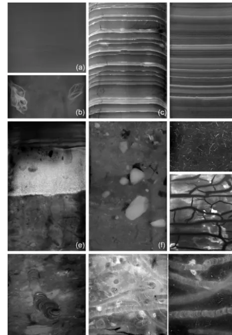
need to be considered. These are described in brief in the fol-lowing examples of typical sedimentary textures as shown in Fig. 7.
Structuresthat may be unrecognizable to the naked eye include boundaries of strata, non-conformities, fine lamina-tion, graded bedding and most importantly – bioturbation (Werner, 1968; Winn, 1974; Wetzel, 1979).Lebensspurenare the most common structures in marine sediments which al-low the identification of the species and the reconstruction of paleoecological and paleoenvironmental conditions (Löwe-mark, 2001). The resulting taxonomy of palichnology is the basis for its identification and classification (Bromley, 1999; Seilacher, 2007). Sedimentological sequences formed by dis-tinct processes (e.g. deposition by turbidity or contour cur-rents) and their evolution over time are also part of this struc-tural group. Features such as base and top boundaries, type, thickness, frequency, rhythms and cycles indicate facies dif-ferentiation and changes.
Physical propertiescan be identified by the brightness of the negatives, as well as by internal structures such as lay-ering (e.g. ash layers), lamination, bedding planes, cross-bedding, current ripples or sorting. By using a magnifying glass while investigating the X-ray image, individual grains with a size of >1 mm can be classified in terms of grain shape and composition. Support of a high-resolution sedi-mentology is given in the millimetre to centimetre scale, in-cluding large components such as mud clasts or gravel grains, e.g. as ice-rafted debris (Grobe, 1987; Principato, 2004). Any gravel fraction reveals itself by the distinct appearance of each individual grain.
have a similar specific grain density of 2.6 to 2.8 g cm−3. Di-atomaceous oozes may result in nearly black X-radiograph negatives because of the low density of opal. Thus, differ-ences in brightness result mostly from changes in grain size rather than from a heterogeneous distribution of minerals. Water content, density and porosity are the major factors governing greyscale values; porosity increases from coarse-grained to fine-coarse-grained sediments. The sediment density and thus the brightness of the image negative increases with core depth because the compaction results in reduced pore space and water content.
Mineralsmay result from diagenesis including authigenic pyrite, zeolite, or the rarely formed porcelanite (Gerland et al., 1997). Heavy minerals such as pyrite and other iron sul-fide as well as iron oxide minerals can easily be identified by their high brightness/X-ray attenuation and their specific grain shapes and internal structures. However, dark grey fea-tures visible in negatives can be areas with an extremely high water content, plant fossils, wood or even small voids. In cases where the samples were stored for a longer period, new minerals may have formed through chemical processes in the sediment (e.g. as per Fig. 6g).
Artefacts reflecting the post-depositional disturbance of the original sedimentary structure must be identified within the core. These effects can have various causes which should always be considered while investigating and interpreting the images (Skinner and McCave, 2003). During the coring pro-cess and recovery, especially with a gravity, kasten, piston or vibrocorer, the mostly soft and often “soupy” sediments from near the seafloor surface (i.e. at the core top) may flow, result-ing in a loss of the original structure. In some instances it is not even possible to prepare a sediment slab suitable for X-radiography from the upper decimetres of the core. Coring disturbance caused by the piston or gravity coring process may result in “pseudo-tectonic” features (e.g. faults, frac-tures, sediment mixing, “flow-in”) which are predominantly observed at the bases of longer piston and gravity cores. In particular, gravity coring can cause micro-faulting within the sediment and result in an artificial shortening of the sedi-ment column (Fig. 6c). Especially in clay-like sequences, even pseudo-hiatuses can occur when parts of a sediment sec-tion succession allow the core barrel to pass but are squeezed out and thus not recovered. In addition, the outer edges of a core segment may show downward bending of layers in close proximity to the core liner, which results from the fric-tion between the liner and the sediment when the core barrel penetrates the seabed.
Further effects visible in radiography might include the following: if the sediment slice is not properly sealed in lay-flat tubing it may dry out and produce drying cracks, which can, however, be clearly identified. If a sediment slice has a variable thickness, the brightness of the X-radiograph will vary throughout the sample. If the sediment contains larger particles, the marginal areas around the particle may be dis-turbed during the preparation. Regular stripes and patterns
Figure 7. Examples of various X-radiographs from the GIK-Archive. Each has a width of 10 cm.(a)Homogeneous clay-like sediment, Mediterranean Sea, https://doi.org/10.1594/PANGAEA. 720925;(b)fossil molluscs, Persian Gulf, https://doi.org/10.1594/ PANGAEA.720253; (c) interbedded strata with artificial down-bending of layers and fault lines as a result of gravity coring, Baltic Sea, https://doi.org/10.1594/PANGAEA.690661; (d) lam-inated sediment, Red Sea, https://doi.org/10.1594/PANGAEA. 720616;(e)turbidite with graded bedding, South China Sea, https: //doi.org/10.1594/PANGAEA.720737; (f)gravel as ice-rafted de-bris, Norwegian Sea, https://doi.org/10.1594/PANGAEA.720368;
(g) pyritized lebensspuren, West Atlantic – off Senegal, https:// doi.org/10.1594/PANGAEA.705737;(h)artificial cracks from dry-ing out of an unprotected sediment slab, https://doi.org/10.1594/ PANGAEA.705491;(i, j, k)examples of bioturbation, Baltic Sea off Flensburger Förde, https://doi.org/10.1594/PANGAEA.705626 and African continental slope, https://doi.org/10.1594/PANGAEA. 705737.
diamic-of the German research vesselsWattenberg,Alkor,Littorina, Poseidon,MeteorandSonne, mostly on expeditions between 1964 and 2000 (Fig. 4). For the list of cores with metadata, please refer to https://doi.org/10.1594/PANGAEA.875415, linked as “Further details” to the parent set. RV Sonne cores collected on behalf of the Preussag manganese nodule project and BGR-led (Bundesanstalt für Geowissenschaften und Rohstoffe, Hanover – Federal Institute for Geosciences and Natural Resources) cruises to the equatorial and South Pacific were also sampled and analysed. Most of the remain-ing material is available in the core storage of GIK and at the Lithothek of GEOMAR Helmholtz Centre for Ocean Re-search Kiel.
Image digitization and archiving
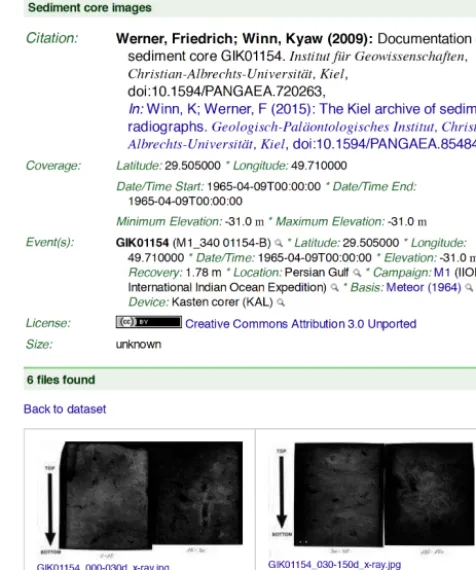
More than 18 500 exposures of X-radiographs were digitized using two A3-format scanners, model Microtek ScanMaker 9800XL, at a resolution of 600 dpi and stored in JPEG for-mat with moderate compression to generate file sizes for con-venient Internet download times. Not all images were post-processed and thus some may still be underexposed. Bright-ness, lucidity and contrast can be corrected as required for vestigation with any image processing software. The full in-formation is in each image due to the high-resolution scan of the fine-grained film. Images were uploaded to PANGAEA and stored in a database. One dataset includes all images of one core. Metadata and additional documentary files includ-ing core descriptions and photos were added, if available. The metadata cover core ID, latitude and longitude, water depth, recovery, coring device and date/time when the core was taken. The label of the expedition linking to the cruise re-port (if published) is also provided. Each dataset starts with a “Citation” tagged line, consisting of the name of the principal investigator(s), a standard title “Documentation of sediment core GIKxxxxx-x”, year of electronic storage and thus pub-lic availability, and the source institute (in this case always set to GIK). The DOI as a persistent link to the dataset is a mandatory part of any modern citation. If the images were al-ready used in publications, the corresponding references can be found under the “Related to” field. Selected examples of images from this collection are presented in Fig. 7.
4 Data availability
The GIK-Archive of radiography is available at https://doi.org/10.1594/PANGAEA.854841.
Figure 8. Example of the standard metadata header provided by PANGAEA from dataset https://doi.org/10.1594/PANGAEA. 720263. Starting with the citation, comprising author(s), year, ti-tle, source and DOI. Citation is followed by the georeference in space and time and links to further references or reports. For this collection, images of each core location have their own data subset. The total of 1355 data subsets of this paper are grouped together in one “parent” dataset (https://doi.org/10.1594/PANGAEA.854841). At the end of the metadata header, each image is shown as a thumb-nail and can be downloaded either individually or as part of a com-pilation of all images in a single zip archive.
ob-jects such as images assists the RDB. For single items or col-lections of files, only the metadata are stored in the relational tables of the data model, including stable links to the image files on tape (Fig. 8).
PANGAEA provides its content not only for direct down-load from its website (http://www.pangaea.de) but also for data harvesting. Besides standard search engines, the image datasets are also distributed via web services through library catalogues, e.g. WorldCat and a number of portals (listed at http://wiki.pangaea.de/wiki/Portal). Most images of a core can be found easily via the PANGAEA query window or even via an Internet search engine by using the (unique) core la-bel as a search phrase. The requested dataset is usually listed among the first search results.
Metadata of PANGAEA are routinely mirrored in Dat-aCite (reference http://data.datacite.org), which is the central entry portal for citable research datasets on the Internet. This information is also stored in the catalogue of the German Na-tional Library of Science and Technology (reference TIB), co-inventor of the data DOI and co-founder of DataCite. Since 2004, PANGAEA has provided its content for OAI-PMH harvesting (Open Archives Initiative – Protocol for Metadata Harvesting). The current operator is OCLC (https: //www.oclc.org) with WorldCat (https://www.worldcat.org), which incorporates the content of repositories following the OAI standard and thus also includes the metadata of the PANGAEA content.
5 Conclusion
With this publication, the complete digitized archive of more than 18 500 radiographs from the World Ocean has been made available to the scientific community. This dataset is publicly available under the CC-BY 3.0 licence (https://creativecommons.org/licenses/by/3.0/) with a persis-tent identifier (https://doi.org/10.1594/PANGAEA.854841) as the Supplement to this publication.
Although X-ray imaging is a method well-suited to sup-plementing the documentation of sediment cores, this tech-nology has been increasingly neglected in some parts of the scientific community because it is time-consuming and new high-resolution analytical techniques (e.g. multi-sensor core logging, X-ray fluorescence and colour scanning) have been continuously introduced and gained priority over the last couple of decades. In addition, digital X-ray images of sediments can now be taken very quickly both on-board and in the lab (e.g. with the ITRAX XRF scanner; Croudace et al., 2006). For the old FAXITRON models a digital X-ray scanner is now available to fit in (NTB, 2005). The time of analogue X-ray imaging of sediments is over and will now continue with digital X-ray devices and X-ray computed to-mography (CT) systems (e.g. Freifeld et al., 2006).
Competing interests. The authors declare that they have no con-flict of interest.
Acknowledgements. With this publication the work of Wilma Rehder and Ursula Faber, technicians at GIK, is greatly acknowl-edged. Both ensured the continuously very high quality of both the sediment slices for X-radiography and of the X-radiographs themselves during many sampling activities on research vessels and at the institute. For nearly four decades they have demonstrated the proper preparation of samples to hundreds of students, as well as guiding them through the exposure and darkroom procedures and archiving the images. We are thankful to Michael Seebeck, who reliably and with great patience digitized those thousands of exposures in a long-lasting workflow. For the improvement of the manuscript the authors are grateful to Michael Sarnthein and Claus-Dieter Hillenbrand.
This article with its supplementary image collection is dedi-cated to co-author Friedrich Werner, head of the sediment core sampling laboratory and core curator at GIK for more than 40 years, who passed away in 2012.
The article processing charges for this open-access publication were covered by a Research
Centre of the Helmholtz Association.
Edited by: David Carlson
Reviewed by: Claus-Dieter Hillenbrand and Michael Sarnthein
References
Bouma, A. H.: Methods for the study of sedi-mentary structures, Wiley, New York, 458 pp., https://doi.org/10.1002/iroh.19710560422, 1969.
Bromley, R. G.: Spurenfossilien, in: Biologie, Taphonomie und Anwendungen, Springer, Berlin/Heidelberg, 347 pp., https://doi.org/10.1007/978-3-642-59832-6, 1999.
Croudace, I. W., Rindby, A., and Rothwell, R. G.: ITRAX: descrip-tion and evaluadescrip-tion of a new multi-funcdescrip-tion X-ray core scanner, in: New techniques in sediment core analysis, edited by: Roth-well, R. G., Geological Society, London, Special Publications, 267, 51–63, https://doi.org/10.1144/GSL.SP.2006.267.01.04, 2006.
Diepenbroek, M., Grobe, H., Reinke, H., Schindler, U., Schlitzer, R., Sieger, R., and Wefer, G.: PANGAEA – an information sys-tem for environmental sciences, Comput. Geosci., 28, 1201– 1210, https://doi.org/10.1016/S0098-3004(02)00039-0, 2002. Exon, N.: Sedimentation in the outer Flensburg Fjord area
(Baltic Sea) since the last glaciation, Meyniana, 22, 5–62, https://doi.org/10.2312/meyniana.1972.22.5, 1972.
Farris, R. A. and Crezée, M.: An improved Reineck Box for sampling coarse sand, Int. Rev. Hydrobiol., 61, 703–705, https://doi.org/10.1002/iroh.3510610515, 1976.
https://doi.org/10.1016/S0025-3227(97)00046-7, 1997. Grobe, H.: Spätpleistozäne Sedimentationsprozesse am
an-tarktischen Kontinentalhang vor Kapp Norvegia, östliche Weddell See, Berichte zur Polarforschung, 27, 1–121, https://doi.org/10.2312/BzP_0027_1986, 1986.
Grobe, H.: Determination of IRD in sedi-ment cores, Polarforschung, 57, 123–345, https://doi.org/10.2312/polarforschung.57.3.123, 1987. Hinz, K., Kögler, F.-C., Richter, I., and Seibold, E.:
Reflexionsseis-mische Untersuchungen mit einer pneumatischen Schallquelle und einem Sedimentecholot in der westlichen Ostsee. Teil II: Un-tersuchungsergebnisse und geologische Deutung, Meyniana, 21, 17–34, https://doi.org/10.2312/meyniana.1971.21.17, 1971. Holyer, R. J., Young, D. K., Sandidge, J. C., and Briggs, K. B.:
Sediment density structure derived from textural analysis of cross-sectional X-radiographs, Geo-Mar. Lett., 16, 204–211, https://doi.org/10.1007/BF01204510, 1996.
Kögler, F.-C.: Das Kastenlot, Meyniana, 13, 1–7, https://doi.org/10.2312/meyniana.1963.13.1, 1963.
Kowalczk, A.: The application of digital x-radiograph imaging for the determination of bulk density, NSF Research Experi-ence for Undergraduates (REU) Project Report (P. Dickhut and C. Friedrichs advisors), Virginia Institute of Marine Science, Gloucester Point, VA, Final Report, CHSD-2005-04, 8 pp, http: //hdl.handle.net/10013/epic.50706.d001, 2005.
Kullenberg, B.: The piston core sampler, Svenska Hydrografisk-biologiska Kommissionen Skrifter, Tredge serien hydrografi, 1, 1–46, http://hdl.handle.net/10013/epic.50738.d001, 1947. Löwemark, L.: Biogenic traces as paleoceanographic indicators
in Late Quaternary sediments from the SW Iberian margin, Berichte-Reports, Institut für Geowissenschaften, Universität Kiel, 14, 138 pp., https://doi.org/10.2312/reports-ifg.2001.14, 2001.
NTB elektronische Geraete GmbH: Digital x-ray scanners of the EZ series, Dickel, Germany, hdl:10013/epic.42410, http:// www.ntbxray.com/products/digital_x_ray_scanner.html (last ac-cess: April 2017), 2005.
Principato, S. M.: X-ray radiographs of sediment cores: a guide to analyzing diamicton, in: Image analysis, sediments and paleoen-vironments, edited by: Francus, P., Kluwer Academic Publishers, Dordrecht, the Netherlands, 165–178, https://doi.org/10.1007/1-4020-2122-4_9, 2004.
gravity- and piston coring based on soil mechanics, Mar. Geol., 199, 181–204, https://doi.org/10.1016/S0025-3227(03)00127-0, 2003.
St-Onge, G., Mulder, T., Francus, P., and Long, B.: Continuous physical properties of cored marine sediments, Developments in Marine Geology, 1, 63–98, https://doi.org/10.1016/S1572-5480(07)01007-X, 2007.
Thiel, H.: Forschungsschiff “Meteor” Reise Nr. 60, SUBTROPEX ’82 Expeditionsprogramm, Deutsche Forschungsgemeinschaft, 23 pp., http://hdl.handle.net/10013/epic.45025.d001, 1982. Werner, F.: Gefügeanalyse feingeschichteter Schlicksedimente der
Eckernförder Bucht (westliche Ostsee), Meyniana, 18, 79–105, https://doi.org/10.2312/meyniana.1968.18.79, 1968.
Werner, F.: Radiographien von Lockersedimenten - Herstellung von Radiographien an Sedimentkernen nach der im GIK üblichen Methode, unpublished report, Geologisch-Paläonotologisches Institut und Museum der Christian-Albrechts-Universität, Kiel (GIK), 9 pp., http://hdl.handle.net/10013/epic.50708.d001, 1975. Werner, F.: 40 Jahre marin-geowissenschaftliche Forschung am Geologisch-Paläontologisches Institut der Universität Kiel, Mey-niana, 50, 7–12, https://doi.org/10.2312/meyniana.1998.50.7, 1998.
Werner, F.: Bioturbation structures in marine Holocene sedi-ments of the Kiel Bay (Western Baltic), Meyniana, 54, 41–72, https://doi.org/10.2312/meyniana.2002.54.41, 2002.
Wetzel, A.: Bioturbation in Spätquartären Tiefwasser Sed-imentation vor NW-Afrika, dissertation, Mathematisch-Naturwissenschaftliche Fakultät der Christian-Albrechts-Universität zu Kiel, 111 pp., http://hdl.handle.net/10013/epic. 50707.d001, 1979.
Whitaker, M. J. and Werner, F.: Pockmarks: Submarine vents of natural gas or freshwater seeps?, Geo-Mar. Lett., 1, 193–199, https://doi.org/10.1007/BF02462433, 1981.
Winn, K.: Present and postglacial Sedimentation in the Great Belt Channel (Western Baltic), Meyniana, 26, 63–101, https://doi.org/10.2312/meyniana.1974.26.63, 1974.
Winn, K.: Bioturbation structures in marine Holocene sediments of the Great Belt (Western Baltic), Meyniana, 58, 157–178, https://doi.org/10.2312/meyniana.2006.58.157, 2006.