0 INTRODUCTION
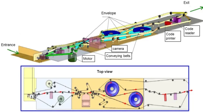
The research presented in this paper is based on the mechanics of mail conveying in sorting machines as used in postal sorting centres. The general concept of these machines is illustrated in Fig. 1. A lot of different technologies are used in such systems: automatic address scanning and recognition, coding printer, etc. For robust machine operation, the correct conveying of the letters has to be ensured, which is equivalent to sustaining a stable position of the envelopes with respect to the belts that transport them. To give an idea, the machine can handle up to 53,000 mail pieces/ hour depending on the length of the pieces processed.
The dynamics of belt transmission has been given a lot of interest and the related litterature is dense. Some of the earliest published works on the topic [1] to [3] were focused on the belt mechanics quasi-static behavior, and the belt-pulley contact friction. A reference paper about the first research on belt vibrations can be found in [4]. Progressively, an following the industry needs, the field of investigation moved to dynamics, durability, vibrations, non-linear dynamics and stability of belt transmissions as exposed in [5] to [7]. The nonlinear phenomena often encountered in flat or poly-v belt transmissions is
caused by parametric excitations due to pulley speed and torque fluctuations that introduce a pulsating tension in the belt [7] to [8]. In most of the studies, an analytical formulation is realized. Several other studies
were developed using a finite element modelling [9],
or also multi-body dynamics theory [10].
The belt dynamics has also been investigated through the topic ‘dynamics of axially moving continua’ which can be applied to string-like or beam-like or plate-like moving systems. In these works, most of the time only a part of the continua is considered with some boundary conditions [11]. In [12]
a thorough recent review on the dynamics of axially moving continua was done, it starts from the earliest works and it details the main contributions of works published on that topic until 2014. It is suprising to see that among this very extensive litterature, no work considers the transportation of mail and the interaction with moving continua.
In the scope of this research, a simulation tool is developed, it predicts the trajectory of a letter being conveyed between two flat belts and crossing several direction switches (Fig. 2) where the envelope/belt contact surface is reduced (Figs. 4a and 5).
Modelling the Belt – Envelope Interactions
during the Postal Mail Conveying by a Sorting Machine
Manin, L. – Braun S. – Hugues D.Lionel Manin1,* – Stefan Braun1 – Damien Hugues2
1 Univ. Lyon, INSA-Lyon, France
2 Solystic SAS, France
The purpose of this study is to predict the trajectory of an envelope when conveyed between two flat belts in a mail sorting machine. Each of the two sides of the envelope is in contact with one belt. The friction coefficient can vary between the two sides, e.g. for the cases of a postcard or a plastic windowed envelope. The two belts are assumed to travel horizontally with the same velocities, but in real world small velocity differences can occur. Also, some deviation from the horizontality of the belts can be observed. These phenomena can lead to unexpected situations where the relative position of the envelope to the belt changes during transportation. The work focuses on the belt-envelope mechanical interactions in order to predict the belt-envelope position during its conveying. A 2D model is developed which considers the dynamic equilibrium of the envelope and simulates the transient behavior at different locations in the sorting machine. In the dynamic friction model, the contact surfaces between the envelope sides and the belts have to be determined at each time step. The belt/envelope friction forces are applied at the centers of these contact surfaces One side of the envelope is considered stuck (in adhesion) to the belt while the other is considered slipping. The position of the envelope center of gravity and the angle with the horizontal axis are calculated. For evaluation of the proposed dynamic model, several cases of operation are simulated.
Keywords: mail sorting machine, belts, envelope, conveying, simulation
Highlights
• Modelling the belt-envelope interactions in mail sorting machine.
1 MODEL DESCRIPTION
The proposed dynamic model is two-dimensional. The envelope, the front and back side belts are considered as vertical planes as illustrated in Fig. 3. The belts have constant and independent velocities and can be inclined with respect to the horizontal axis. The aim is to determine the envelope position as a function of time. The dynamic equilibrium of the envelope is written at the mass centre G. The forces considered are the weight of the envelope and the friction forces of the belts onto the envelope sides. The contact surfaces have to be determined at each time step of the simulation process. The proposed method is presented in the next paragraphs.
1.1 Parameter Definition
The envelope is defined by: its height hp and width
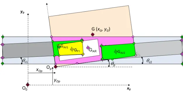
lp, its mass mp and inertia Ip, the posi-tion of the plastic window if any and its size (hf * lf), the mass centre coordinates (xG, yG), the left bottom corner coordinates (xOp, yOp), the initial angle with respect to the horizontal axis θp. The belts are defined each by the coordinates of the two lower corner points and the width (Fig. 3). From these geometry input parameters, the angles between the belts and the horizontal axis are deduced.
When the envelope is travelling through a direction switch (Fig. 2) the contact surface with the front belt(s) are more complicated to determine than
Fig. 1. Schematic representation of a mail conveying machine
a) b)
the contact surface with the backside belt. This is due to the front belt being divided into two neighboring belts, introducing a dis-continuity. As the envelope passes this discontinuity, five contact cases can occur as shown in Fig. 4a. These cases are implicitly taken into account with our parameter definition. A standard mail sorting machine contains several successive direction switches which can be rep-resented by the scheme in Fig. 4b. In that case, multiple front belts are considered as on the machine.
2.2 Forces Acting on the Envelope
Theoretically the front and rear belts have the same velocities. However, a small difference can exist which is estimated at around 5 %. We have made several assumptions when setting up the model: the envelope is adhering to the slowest belt (rear or front) and is sliding with respect to the fastest belt(s). To give an example: if the rear belt is slower than the two front belts (Fig. 5) then the envelope is
Fig. 3. Geometry parameters for the belts and the conveyed mail envelope, general case including a sorting switch
a) b)
Fig. 4. a) Contact cases between belts and envelope when travelling through a direction switch, b) conveying with several direction switches
can be estimated from Eq. (1), where Sp_totalis the total contact surface with the envelope paper, Sf the contact surface with the plastic window, and the friction coefficients fp and ff (belt/envelope, plastic window/ envelope). If Eq. (1) is satisfied then the envelope does not fall.
p S⋅
(
p total_ ⋅fp+S ff ⋅ f)
≥m gp⋅ . (1)The friction forces are calculated for each contact surface Si using the belt/envelope contact pressure p (supposed constant and uniform), the angles of the belts θcj, the friction coefficients fi and the velocities of the belts (Eqs. (2) and (3)). In Eq. (4) the terms inside the parenthesis are considered only if the Eq. (1) is not satisfied.
Fx i, =sign V
(
frontj−Vrear)
⋅ ⋅ ⋅ ⋅f p Si i cosθcj, (2)Fy i, =sign V
(
frontj−Vrear)
⋅ ⋅ ⋅ ⋅f p Si i sin .θcj (3)F
F
F m g f p S f p S
ext
i x i
i y i p f f p p total
= +
( )
(
− + ⋅ + ⋅)
⋅ ⋅ ⋅∑
∑
, , _ ,(4) M exti x i G Si y i Si G
j x j G Sj
G F y y F x x
F y y F
( )
=(
⋅(
−)
+ ⋅(
−)
)
+⋅
(
−)
+∑
+ ∑
, ,
, yy j, ⋅
(
xSj−xG)
(
)
, (5)
m d x dt m d y
dt I d dt F F p G p G p p ext x ext y 2 2 2 2 2 2 θ = ,, M M where ext
p p p p
G
I m l h
( )
=(
+)
12 2 2. (6)
As already mentioned, a key point is the determination of the different contact surfaces Si and
their mass centres Gi where the friction forces are
applied. This is developed in the next paragraph. The envelope is subjected to its proper weight and to the friction forces applied by the front and rear belts. The dynamic equilibrium of the envelope in the vertical plane can be written with:
• the sum of external forces equalling the mass of the belt times its acceleration,
denotes the friction forces on the envelope paper,
the subscript f denotes the friction forces on the
envelope plastic window. The moment of the friction
forces expressed at point G is given in Eq. (5). The
coordinates of each contact surface centre Gi are (xSi, ySi). Finally, the equations of motion of the envelope are given in Eq. (6).
An Euler iterative numerical scheme is used to solve Eq. (6), as detailed in Eqs. (7) to (9). One should note that at each time step the contact surfaces and their centre coordinates change and have to be re-calculated. Some initial conditions are considered depending on the running conditions simulated (Eq. (10)).
x x dt F
x x dt x
n n ext
n n n
n + + = + ⋅ = + ⋅ 1 1
, (7)
x dx dt dy dt d dt x x y G G p G G p = = θ θ
, , (8)
x x dt F
x x dt x
n n ext
n n n
n + + = + ⋅ = + ⋅ 1 1
, (9)
x x y x V x G G p rear 0 0 0 0 0 0 0 0 0 0 0 = = = _ _ _ θ , =
, Fext _ . 0 0 0 0 (10)
2.4 Calculation of the Contact Surfaces
The contact surfaces Si are represented by polygons
Pi (Fig. 5). They are the intersections between the
points in order to determine the contact surfaces and their mass centres (Fig. 6).
In literature, this problem is known as polygon
clipping, often found in computer graphics [13]. In
order to determine the intersection polygons, we use a polygon clipping technique from computer graphics. Many algorithms have been proposed in literature to solve this problem. For our implementation, we use the Vatti clipping algorithm [14]. This algorithm enables us to determine the intersection of arbitrarily shaped polygons in a two dimensional space. Once the intersection polygons are determined, the surface areas and mass centres are calculated using the ‘polyarea’ and ‘centroid’ functions of Matlab.
2.5 Input Data
The data defining the system are gathered in an Excel file which is read by the simulation program under the Matlab environment. An example is given in Table 1. From these input data, the system can be represented graphically as shown in Fig. 7.
3 RESULTS
3.1 Test Cases
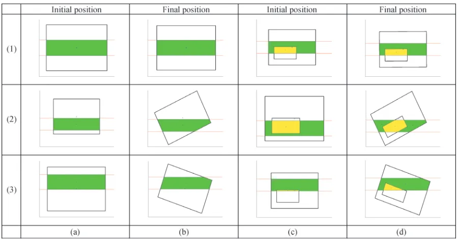
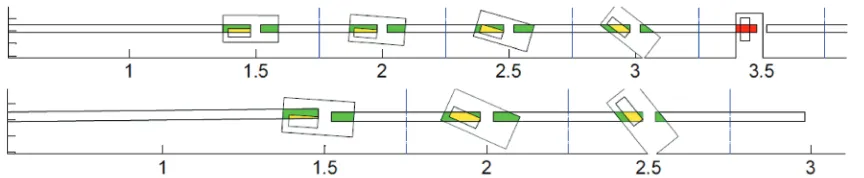
In order to validate the model developed, some simulation test cases have been considered. They are based on real observations made on a mail sorting machine, and also on some intuition on how the envelope position will evolve under different running conditions. The test cases are presented in Fig. 8. All tests were done for two different types of envelope:
one without and one with a plastic window. The envelope is adhering to the rear belt and the rear belt is slower than the front belt, no direction switch is
Fig. 6. Contact surfaces between the front belts and the envelope paper (green/daker) and plastic window (yellow/lighter)
Fig. 7. Representation of the mail sorting machine with the parameters of Table 1
Table 1. Geometry parameters of the belts
Front belts X1
[m] [m]Y1 [m]X4 [m]Y4 [m]lb [m/s]lb
1 0.500 0.044 1.500 0.044 0.030 4.00
2 1.540 0.044 3.000 0.044 0.030 4.00
3 3.040 0.044 4.500 0.044 0.030 4.00
Rear belts X1
[m] [m]Y1 [m]X4 [m]Y4 [m]lb [m/s]lb
1 0.500 0.044 5.000 0.044 0.030 3.99
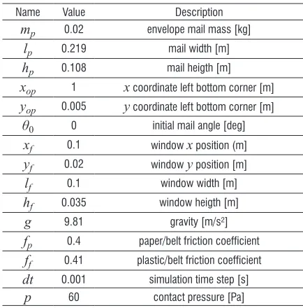
Table 2. Envelope and simulation parameters
Name Value Description
mp 0.02 envelope mail mass [kg]
lp 0.219 mail width [m]
hp 0.108 mail heigth [m]
xop 1 x coordinate left bottom corner [m]
yop 0.005 y coordinate left bottom corner [m]
θ0 0 initial mail angle [deg]
xf 0.1 window x position (m]
yf 0.02 window y position [m]
lf 0.1 window width [m]
hf 0.035 window heigth [m]
g 9.81 gravity [m/s²]
fp 0.4 paper/belt friction coefficient
ff 0.41 plastic/belt friction coefficient
dt 0.001 simulation time step [s]
considered. When the inertia centre of the envelope is centred with the belts, no rotation is observed for the envelope without window (Fig. 8 (1-b)), but a slight rotation is observed for the envelope with a window (Fig. 8 (1-d)). This is due to the difference of friction coefficients between the paper (fp) and the plastic (ff) with the belt. When ff > fp , the consequence is the generation of an anticlockwise moment that initiates the envelope rotation.
The influence of the envelope inertia centre position with respect to the belt is highlighted with the simulation cases 2 and 3 in Fig. 8. A rotation is generated by the unbalance of the friction force moments. This phenomena is amplified when the envelope has a plastic window. The final positions obtained for the several test cases correspond to those that were expected and confirm the viability of the model.
The vertical position of the inertia centre yG and the rotation angle θp are plotted versus the conveying distance in Fig. 9. When the envelope is passing through a direction switch, there are three phases where the contact surfaces are reduced (Fig. 4a) and there is a risk of falling for the envelope if the vertical friction forces are smaller than the envelope weight, as illustrated in Fig. 9. Several running conditions can be simulated, we only present here some results to show the capabilities of the model. The friction
coefficient values were given by the sorting machine manufacturer that had made some measurements. The important point for the simulations is that the paper/ belt friction coefficient should differ from the plastic/ belt friction coefficient, so that the effect of the plastic window on the envelop trajectory can be identified.
3.2 Simulation of a Conveying
Several generic cases of mail conveying are considered (Fig. 10). The graphical interface enables the visualization of the successive positions taken by the envelope. Some alerts have been implemented in the code so that when the envelope reaches a position which is no more realistic, the simulation is stopped. For example, if the lower point of the envelope has a negative vertical coordinate, or the rotation angle is larger than 30° then the simulation is stopped.
4 CONCLUSIONS
The work described in this paper deals with the simulation of the mail conveying in a postal sorting machine. It is based on an industrial demand and therefore corresponds to real issues encountered in such machines. The intention was to develop a simple simulation model in order to predict the envelope trajectory in the mail sorting machine under different
operating conditions. The model developed considers simple or windowed envelopes. Some assumptions were made in order to simplify the analysis and the dynamic equilibrium. The forces considered are the envelope’s weight and the friction forces applied by the front and rear belts between which the envelope is maintained. The data definition permits the simulation of machines with several direction switches. These switches happen to be the most critical situations in the conveying process. The proposed model is very flexible, as the dimensions of the envelope can be changed as well as all the other parameters describing the geometry of the conveying path. The core of the model relies on the calculation of the contact surfaces between the envelope sides and the belts for each simulation time step. This is based on the theory of polygon clipping that permits the computation of intersection surfaces. Evaluation of several test cases showed that the results obtained by simulation are consistent with real world observations and permit to explain several phenomena encountered.
5 ACKNOWLEDGEMENTS
The authors are very grateful with the Solystic Company that has partly financed the work presented.
6 REFERENCES
[1] Firbank, T.C. (1970). Mechanics of the belt drive. International Journal of Mechanical Sciences, vol. 12, no. 12, p. 1053-1063, DOI:10.1016/0020-7403(70)90032-9.
[2] Childs, T.H.C. (1980). The contact and friction between
flat belts and pulleys. International Journal of Mechanical Sciences, vol. 22, no. 2, p. 117-126, DOI:10.1016/0020-7403(80)90048-X.
[3] Gerbert, G. (1999). Traction Belt Mechanics, MVD, Chalmers, Göteborg.
[4] Abrate, S. (1992). Vibrations of belts and belt drives.
Mechanism and Machine Theory, vol. 27, no. 6, p. 645-659,
DOI:10.1016/0094-114X(92)90064-O.
[5] Parker, R.G., Lin, Y. (2004). Parametric instability of axially moving media subjected to multifrequency tension and speed
fluctuation. Journal of Applied Mechanics, vol. 68, no. 1, p. 49-57, DOI:10.1115/1.1343914.
[6] Pellicano, F., Catellani, G., Fregolent, A. (2004). Parametric instability of belts: theory and experiments. Computers & Structures, vol. 82, no. 1, p. 81-91, DOI:10.1016/j. compstruc.2003.07.004.
[7] Michon, G., Manin, L., Remond, D., Dufour, R., Parker, R. (2008). Parametric instability of an axially moving belt subjected to multifrequency excitations: experiments and analytical validation. Journal of Applied Mechanics, vol. 75, no. 4, DOI:10.1115/1.2910891.
[8] Michon, G., Manin, L., Parker, R.G., Dufour, R. (2008).
Duffing oscillator with parametric excitation: analytical and
experimental investigation on a belt-pulley system. Journal of
Fig. 9. Envelope vertical position and angle qp while passing through a direction switch
[10] Čepon, G., Manin, L., Boltežar, M. (2009). Introduction of damping into the flexible multibody belt-drive model: A
numerical and experimental investigation. Journal of Sound and Vibration, vol. 324, no. 1-2, p. 283-296, DOI:10.1016/j. jsv.2009.02.001.
[11] Čepon, G., Boltežar, M. (2007). Computing the dynamic
response of an axially moving continuum. Journal of Sound
[13] Agoston, M.K. (2005). Computer Graphics and Geometric Modeling – Implementations and Algorithms, Springer, London, DOI:10.1007/b138805.
[14] Vatti, B.R., (1992) A generic solution to polygon clipping.
Communications of the ACM, vol. 35, no. 7, p. 56-63,