0 INTRODUCTION
In recent years, fuel costs have risen dramatically due to the acceleration of energy consumption. Due to global warming, countries have enforced new requirements for energy-saving and emission-reduction in large construction machinery [1].In the operation of construction machinery, it is possible to reuse and recycle energy because of the cyclic change of workload [2].
The energy recovery system can be divided into hydraulic and electrical parts. Minav et al. proposed using a forklift as an experimental platform for comparing hydraulic with electrical recovery schemes in terms of fuel consumption and service performance
[3] and [4]. It can be seen from the results that the hydraulic type is the better choice rather than the electric one in terms of fuel-saving rate. However, the hydraulic effects are rather limited in the load range, for which the overall energy-saving effects of electrical types can be better. Lin et al. employed hydraulic and electrical methods to recover the excavator boom potential energy [5]. The results have demonstrated that the hydraulic speed is the better choice compared
to the electric one in controlling the speed of moving arms. Gong et al. showed that the potential energy of forklift is stored in the supercapacitor by the motor, where the experimental evaluation is also carried out. Specifically, comprehensive energy-saving effects of 20.8 % can be reached [6] and [7]. Yu and Kwan conducted simulations to analyse the boom potential of the excavator by hydraulic transmissions. Compared to the traditional accumulator recovery, it has not yet been experimentally verified [8]. Lin et al. considered the dynamic stability of hydraulic recycling and the economic nature of the electrical system [9]. Combining the advantages of hydraulic and electric recovery, the utility model can be applied to the recovery of the potential energy of the movable arm of the excavator. These results have demonstrated that the new system can increase the fuel-saving rate and reduce the installed capacity of the generator by 65 % compared to the traditional hydraulic recycling method.
From the system structure perspective, the system can be categorized into series, parallel, and hybrid systems. Kwon et al. have investigated the series, parallel, and hybrid connection systems of excavator
Investigation of the Energy Regeneration
and Control Strategy of a Crane Hoisting System
Chen, Y. – He, J. – Wu, K. – Zhao, Y. – Wang, Z.Yi-long Chen1 – Jilin He1,* – Kang Wu2 – Yu-ming Zhao1,2 – Zhi-jie Wang2
1 Central South University, College of Mechanical and Electrical Engineering,
State Key Laboratory of High Performance Complex Manufacturing, China
2 Sunward Intelligent Equipment Co., Ltd, China
The crane can be used for large mechanical equipment of hydro-mechatronic heavy lifting and transfer operations, and has been widely used in many practical applications such as construction and emergency rescue. Although the winch system is one of the main parts of a crane hoisting device, large amounts of energies are wasted rather than being effectively used during the working process. In this paper, the potential of energy regeneration is analysed, and the reuse of the winch system can be performed by the following steps. First, an energy recovery system was proposed, based on the mechanical connection with the winch-motor-synchronous motor and the analysis of energy loss mechanism in the winding down process. Second, the calculation formula of the energy recovery rate was derived, in which the dynamic coupling characteristics of the system and the factors affecting the energy recovery rate were also analysed. Third, the control strategy of an energy-saving system was developed, aimed at minimizing fuel consumption. Finally, the experimental platform was built by using a certain type of 25T rough terrain crane. The experimental results have demonstrated that the systematic scheme and control strategy are rational and feasible.
Keywords: crane, hoist system, energy regeneration system, control strategy, hybrid system
Highlights
• A parallel energy recovery system based on winch-motor-synchronous motor was proposed.
• Analysis of crane hoist hydraulic system energy flow. The experimental results show that the braking energy of the hydraulic motor can account for more than 60% of the total gravitational potential energy.
• The experimental results show that the potential energy recovery rate of energy recovery system is about 45 % to 65 %. • According to the potential energy recovery rate, determine the energy recovery system operating conditions.
energy-saving systems [10]. The results have shown that the hybrid method is more advantageous, as the feedback time is shorter than the other two types of coupling systems. Wang and Wang proposed optimizing parameters of the permanent magnet synchronous motor (PMSM), where the fuel-saving rate can be improved in the series system [11].
For hoist systems, the potential energy recovery of excavator and forklift can provide a new direction for energy-saving research and technology. Dai proposed a hybrid system that employed accumulators as energy storage components [12]. Wu et al. proposed a winch two-regulation system, where the accumulator is used to recover the gravitational potential energy released by a hoist when it is lowered [13].
For the control algorithm, Kim et al. proposed an algorithm with the consideration of an equivalent fuel minimization strategy [14]. The efficiency of the diesel engine can be improved by adjusting the speed of the motor appropriately. Xiao et al. proposed the control strategy for a dynamic working condition, where the state of charge (SOC) of the capacitor would fluctuate within a very small range [15].
The above-reported research has shown that much of the habitual performance of swing machinery such as excavators and boom would be consumed during the starting and braking process. The use of hydraulic accumulator-type recycling can quickly release energy and recovery effects, which can obtain better results. For some potential changes in the system, the use of electric energy recovery should be considered due to the capacity limitations of the accumulator storage. The main objective of the control algorithm is to ensure the performance of the premise, and to reduce the fuel consumption of the system as much as possible.
In this paper, the investigated crane hoisting system (CHS) is required to increase and decrease frequently from several tons to tens of tons of cargo during the operating process. The vertical distance of rise and fall can be more than ten meters, where a large amount of potential energy would change in the declining process. Therefore, the electric recovery mode is adopted. In terms of the system structure, the excessive cost and complexity of the component are required to be increased, although the hybrid type is good at saving energy. Therefore, the parallel structure is employed in this paper.
The rest of the paper can be structured as follows. In Section 1, the energy regeneration methods for CHS are demonstrated. Section 2 describes the control strategies in detail. Extensive analysis of experimental
results and discussions are described in Section 3. Lastly, concluding remarks are presented in Section 4.
1 ENERGY REGENERATION METHODS FOR CHS
1.1 Working Style
The CHS mainly consists of hydraulic motor, balance valve and reversing valve, which is shown in Fig. 1. If the hoist falls, the pump outlet flow can be divided into two parts. Part of the flow goes to the motor and balance valve 1, which is used for load braking. The other part of the flow goes to the balance valve 2, which is used to open the balance valve. In the course of winding down, the change of the potential energy of the weight EG where it’s EG= mgh.
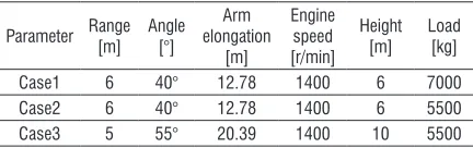
Table 1. Winding down condition
Parameter Range [m] Angle [°] Arm elongation [m] Engine speed [r/min] Height [m] Load [kg]
Case1 6 40° 12.78 1400 6 7000
Case2 6 40° 12.78 1400 6 5500
Case3 5 55° 20.39 1400 10 5500
This part of potential energy is consumed by the motor and the balance valve. Therefore, the variation of gravitational potential energy should satisfy:
EG =EQbb +EQm. (1) The expression of each component is given as:
EQm=
∫
ttQ P dtm∆ m0 1
, (2)
EQ t Q P dtbb t
b
bb =
∫
0 ∆ 1, (3)
where EQm is motor brake energy consumption, EQbb
is balance valve braking energy, Qm is pump output
flow, Qbb is the flow of the balance valve 1, ΔPm is the
difference of inlet and outlet pressure of the motor and ΔPb is the difference between the inlet.
To verify Eq. (1), each part of the consumed energy during the roll down process is tested. The experimental conditions are set according to the actual operation of the crane and adjusted with the following three points:
First, it is secure. According to the working condition table of a certain type of 25-ton off-road tire crane, the selected working condition is within its working range.
Therefore, the length of the main arm is at the full extension of the one arm and the full extension of the two arms. Moreover, the lifting load reaches fifty percent of the rated load.
Third, it is feasible. According to the system structure, shown in Fig. 1, the leakage of the motor can be ignored, and the flow of the balance valve is always equal to the flow of the motor when the hoist is down. Thus, the engine speed is set as a fixed value. In addition, only the potential energy of the hoist system is recovered in this paper, so the experimental conditions do not include the movements of amplitude, rotation and so on.
The experimental operation of the crane is shown in Fig. 2, and the parameters of the experimental working condition are shown in Table 1. The energy consumption of the motor braking and the braking energy of the balance valve can be calculated under these conditions; the results are shown in Table 2.
Fig. 1. Schematic diagram of the balance valve
The average of the data is calculated under three conditions, where the energy of the motor brake and the momentum of the balance valve are around 62.1 % and 37.8 % of the gravitational potential energy, respectively. It can be concluded from the experimental data, it is known that the braking energy of the hydraulic motor can account for more than 60 %
of the total gravitational potential energy, and there is a large space for energy recovery.
Table 2. Results of energy flow tests
Project Case
Case1 Case1 Case1
Motor brake EQ
m [kJ] 244.5 211.0 333.2
Balance valve brake EQ
bb[kJ] 174.9 146.9 234.2
Potential energy EG [kJ] 411.6 323.4 539.0
EQm/ EG [%] 59.4 65.2 61.8
EQbb/ EG [%] 42.5 45.5 43.5
Fig. 2. Schematic diagram of crane experiment operation
1.2 Configurations of the Energy Recovery System
Based on the analysis of the energy consumption mechanism, the potential energy recovery is a key component for saving energy. By considering the recovery of potential energy, the system should include an energy storage device, for the potential energy wasted in the process of load distribution. Subsequently, the recovered energy can be used if the load rises. To achieve this objective, a hoist with a double-speed reducer is designed to recover the gravitational potential energy, where the control strategy of the system can be obtained. The schematic of the system is presented in Fig. 3, and the real system is presented in Fig. 4.
The second is the balance valve. This component can be used for the motor brake and unlock, as well as for protecting the system. The third is the multiway valve group, where motor commutation can be completed by the use of this part. The fourth is the quantitative pump, which is used to provide power for the system. The fifth is the PMSM, which is the energy recovery device of the system. The sixth is the lithium battery for energy storage.
Fig. 3. Energy recovery system structure
Fig. 4. Energy-saving system physical map
The energy recovery process of the system can be divided into two stages, namely, load rise and load drop. When the load decreases, the pilot oil would slowly unlock the hydraulic motor. When the inlet pressure reaches the set pressure of the balance valve, the balance valve port will be opened. In the initial stage of the decline, the working load would start to accelerate from the static state since the output torque of the hoist motor is less than the load torque. From the hoisting system to the steady state, the PMSM is simultaneously driven by the motor and the heavy load when the PMSM enters the power generation state. The alternating current generated by the PMSM is converted into the direct current by a frequency converter, which is later stored in a lithium battery.
When the load decreases to the desired height, the hydraulic motor port is cut off and the load is braked. Meanwhile, the power generation mode is turned off in the PMSM. When the load increases, the pilot oil slowly unlocks the hydraulic motor, and the hydraulic motor drives the hoist to rise. When the load rising speed reaches to the motor starting speed, the PMSM would enter the electric mode. In this case, the PMSM and the hydraulic motor would drive the load together. The recovered energy from the battery can go through the inverter to feed power to the motor. If the load reaches the required height, the handle can return to the middle position, where the inlet pressure can decrease, and the check valve can close. Subsequently, the brake oil-cylinder releases the pressure, so that the hydraulic motor is locked by the hydraulic lock. Finally, the motor output zero torque is separated from the system.
In this system, the PMSM is connected with the motor through the hoist, which can reduce the energy conversion in the energy utilization process.
2 CONTROL STRATEGY
There are three goals to be achieved for a control strategy. The first is to improve the recovery efficiency, where the distribution of the working points of the PMSM can be guaranteed to be in or near economic viability. The second is to stabilize the SOC value of the battery within the operating range, which can be achieved by adjusting the working point of PMSM. Finally, the last goal is to make sure that the hoisting system can operate with desirable performance. In other words, the displacement of the motor and pressure matching should be successfully obtained; the control strategy is illustrated in Fig. 15. More specifically, this strategy is based on the following principles.
2.1 Step 1: Working Mode of the PMSM
According to Section 1.2, the PMSM is an energy recovery device, but the energy recovery is not always economical. To reach the minimum fuel consumption of the system, the working mode of the synchronous motor is indirectly determined by analysing the main factors that affect the fuel-saving rate.
2.1.1 Fuel Consumption in the Hoist System under the Ordinary Mode
stages: rising and falling. During the rising stage, the fuel consumed by the engine is mainly used to overcome the load gravity, while the fuel consumed in the down stage is mainly used to brake the working load (the brake is completed by the motor and the balancing valve, which is equal to the variation of the gravitational potential energy) and the opening balance valve.
According to Section 1.1, the balance valve consists of two parts: balance valve 1 and balance valve 2, which are shown in Fig. 1. Assuming that the two parts of the ratio of the number of damping holes is 1/n, the relationship between the flow of the balancing valve 1 (Qbb) and the flow of the balance
valve 2 (Qbo) can be summarized according to the
fluid continuity equation:
Qbb= nQbo. (4) Therefore, the energy consumed by balance valve is:
Eb=Ebo+Ebb. (5) The expression of each component can be given as:
E
n Q P dt
bo=
∫
∆ b1
1+ , (6)
E n
n Q P dt
bb= +
∫
∆ m1 , (7)
where Ebo is the energy consumed by opening the
balance valve, Ebb is the energy consumed by braking
the hoist system, Q is flow through the balance valve, and its value is equal to the sum of Qbb and Qbo, ΔPm
is the difference of inlet and outlet pressure of the motor, and ΔPb is the difference between the inlet and
outlet pressure of the balance valve.
Therefore, the common mode of fuel consumption can be obtained as follows:
E mgh mgh
Q P nt b = + + ∆ + ( ) ,
1 2 2
1
η (8)
where h1 is the load rise height, h2 is the load drop height, m is working load, η is efficiency of diesel engine, t1 is the load rise time, and t2 is load down time.
2.1.2 Fuel Consumption in the Hoist System under the Energy-Saving Mode
Compared with the normal mode, in the energy-saving mode, during the ascending stage, the fuel consumed
by the engine is mainly used to overcome the load gravity, which is partly provided by the motor, and the other part is provided by the engine because of the traction of the motor.
Therefore, the energy-saving mode of fuel consumption can be obtained as follows:
E mgh P t
nQ P n
Q P n t
S
d m b
= − + ∆ + + ∆ + ( ) ( ) ,
1 1 2
1 1
η (9)
where Pd is the generated power for the PMSM.
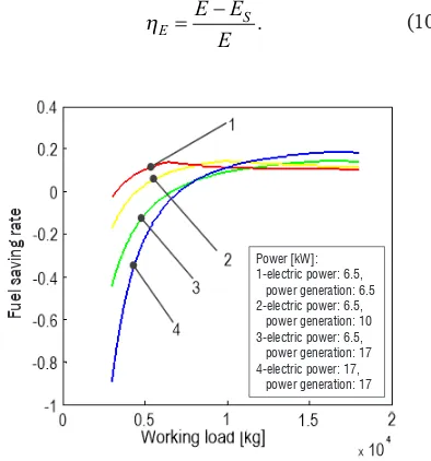
2.1.3 The Fuel-Saving Rate
Based on Sections 2.1.1 and 2.1.2, the fuel-saving rate can be defined as:
ηE E ES
E
= − . (10)
Power [kW]: 1-electric power: 6.5, power generation: 6.5 2-electric power: 6.5, power generation: 10 3-electric power: 6.5, power generation: 17 4-electric power: 17, power generation: 17
Fu
el sa
ving rat
e
Fig. 5. The fuel-saving rate (changing working load)
2.2 Step 2: The PMSM Control
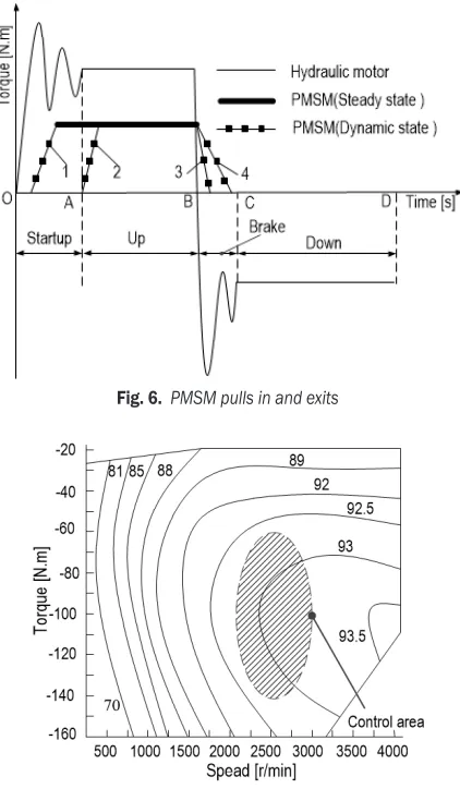
2.2.1 Pull in and Exit of PMSM
Fig. 6 represents the torque of the hydraulic motor and the PMSM. Among them, the OA segment, AB segment, and BC segment represent the lift and acceleration phase, the uniform rising phase and the deceleration braking phase, respectively.
In Fig. 6, the ascent curve 2 is higher than the curve 1, where the motor is able to operate in high efficiency zones. In the descent stage, the braking performance of curve 3 is better than that of curve 4.
Fig. 6. PMSM pulls in and exits
Fig. 7. PMSM’s efficiency map
In Fig. 7, the efficiency diagram of the synchronous motor is shown. In view of the low efficiency of the motor at low speed, the PMSM is selected to run at a given minimum speed. When the motor exits the system, the torque of the hydraulic motor would change from “positive” to “negative”,
where the torque of the motor should immediately become zero for system to quickly break.
2.2.2 Determination of Power Generation for PMSM
Based on the recovery rate of potential energy, the power generation of the motor can be determined.
In order to calculate the recovery rate of potential energy, the torque of the PMSM and load is converted to the hydraulic motor shaft. The equation of torque balance is as follows:
T Tg− m−Tw=0, (11)
where Tg is produced by the PMSM and is converted to the torque on the shaft of the hydraulic motor, Tm is
the output torque of the hydraulic motor, and Tw is the
torque generated by the working load and is converted to the shaft of the motor.
According to Eq. (11), the torque direction of the motor is determined by the load torque and the generator torque. When Tg > Tw, one part of the
recovered electricity is from the change of the potential energy of the load, and the other part is from the work done by the motor. When calculating the recovery rate of potential energy, the electric energy generated by the hydraulic motor should be subtracted. However, when Tg < Tw, all the electrical energy recovered
at this time is from the change of the gravitational potential energy. Therefore, potential recovery can be defined as the ratio of the gravitational potential energy recovered by the executive mechanism to the existence of the gravity potential energy of the system. This quantity can measure the ability of the system to recover potential energy. The potential energy recovery rate of the CHS can be expressed as follows:
ηG
g m
G g w
g
G g w
E E
E T T
E
E T T
= −
≥
<
. (12)
The component expressions are defined as:
EG =mgH, (13)
Em= ∆P Q tm m, (14)
Eg =P tg , (15)
where EG represents the gravitational potential energy released by the hoisting process, ΔPm is motor import
work done by motors, and Eg is the electrical energy
produced by a generator.
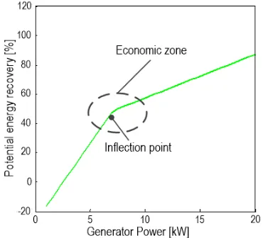
If the load is fixed, the power generation is changed; the potential energy recovery rate is shown in Fig. 8. The recovery of potential energy will increase with the increase of the generator power. However, the motor would result in Tg > Tw, where one part of the
energy recovery can be obtained from the hydraulic motor. Therefore, the rate of potential energy recovery can be reduced. When the load is low, it becomes inefficient to increase the potential energy recovery rate by increasing the generator power. Therefore, the most economic point is close to the inflection point. In other words, it would be better to set the range of potential energy recovery between 45 % to 65 %.
Fig. 8. Potential energy recovery (change generator power)
Fig. 9. Fuel-saving rate (change motor power)
2.2.3 Determination of Electric Power of PMSM
According to Eq. (10), the fuel-saving rate can be determined by the motor, the electric power and the
power generation when the load is fixed. An example is given by considering the working load of 7 tons. The motor power generation and electric power can be changed; the fuel-saving rate is shown in Fig. 9. In this figure, it can be seen that the fuel-saving rate is the highest when the electric power is close to the power generation. In other words, the rate of oil saving is the highest when the consumed electric energy is equal to the recovered electric energy. Therefore, the initial electric power selection should be equal to the power generation.
2.3 Step 3: SOC Control Strategy
The SOC value can be estimated as follows:
SOC SOC i dt C
ini
= +
∫
η . (16)The constraints of SOC value can be defined as follow:
SOCmin ≤ SOC ≤ SOCmax , (17) where SOCini is the initial SOC of the battery and i is the current of the battery. In particular, the charge is positive, the discharge is negative, η is the efficiency of charge discharge, SOCmax is the upper limit of the allowable state of the capacitance, and SOCmin is the limit of the allowable capacitance.
According to Eq. (16), the charging and discharging current of the battery can be determined by the generation voltage of the permanent magnet synchronous motor and the line current of the electric rotor. In general, the generation voltage of PMSM cannot be adjusted. The reason is that the battery current would flow back, and reverse discharge results would appear, if the voltage were too low. Therefore, the discharge current can be regulated by adjusting the rotor current. In practical application, the current of the rotor is controlled by a frequency converter; the controller can indirectly control the discharge current given the PMSM power or torque.
becomes stable and safe. The principle of the system is given in Fig. 10.
Fig. 10. SOC value of the control system
2.4 Step 4: Motor Pressure and Displacement Matching
Control Strategy
2.4.1 Dynamic Load during Hoisting
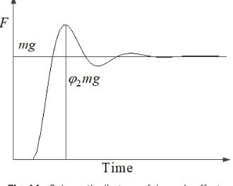
When the load is freely lifted from the ground, the inertia and impact of the load increase the lifting load. As shown in Fig. 11, the lifting force effect can be measured by φ2PQ, where φ2 is the lifting load factor larger than 1 and PQ is the lifting load, where it is PQ = mg.
Fig. 11. Schematic diagram of dynamic effect
The lifting dynamic load factor can be defined as: ϕ2=ϕ2min+β υ2 q, (18)
where φ2min is the minimum value of the dynamic load coefficient corresponding to the rising state level, β2 is the coefficient to be set based on ascending state levels, and υq is the stable lifting speed.
2.4.2 The Relationship between Displacement and Winch Motor Pressure
As shown in Fig. 12, the geometric capacity of the hydraulic motor would decrease with the increase of the pressure in the normal mode, where the star represents the effective capacity in the energy-saving mode. This phenomenon is caused by the opening
amount unchanged in speed of the engine and the control valve under the constant output flow system. Therefore, the lifting dynamic load generated by the torque of PMSM can increase, resulting in rise of stable lifting speed and reduced motor displacement.
Fig. 12. Pressure and displacement of winch motor
2.4.3 Compound Control Strategy
If the hydraulic motor is used for lifting heavy objects, the braking performance should be properly considered to prevent heavy objects from falling. The motor brake performance can be evaluated by the sliding value of the motor shaft when the inlet and outlet of the motor are cut off. When the actual motor displacement is less than the theoretical one in the energy-saving mode, the hydraulic oil apparently cannot be filled with the motor cavity. As a result, the braking performance can be decreased. To avoid this issue, the feedforward control is added on the original feedback control strategy. In this paper, the motor displacement and pressure matching control strategy are proposed.
Since the hydraulic motor is connected to the motor by a rigid shaft, the actual speed of the motor can be obtained from the feedback of the synchronous motor. In theory, the displacement of the motor is related to the load and the torque acting on the motor shaft. The geometric capacity of the hydraulic motor
Dmt can be expressed as:
Fig.13. Block diagram of compound control
valve can be satisfied when the motor is pulled into the system, which can be expressed as Eq. (20).
K Xq v'−K Pc L= f T T( L− D) .θ (20)
By using the Laplace transformation, the following can be obtained.
K Xq v' −K Pc L= f T T( L− D)θS. (21)
Therefore, the feedforward control can be added to the original feedback control, where the control block diagram is illustrated in Fig. 13.
3 RESULTS AND DISCUSSION
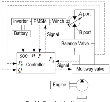
To investigate the effect of the energy-saving system, a test rig was constructed (Fig. 14). A computer is used as the controller with the following parameters. The A port pressure of hydraulic motor is PA, the B port
pressure of hydraulic motor is PB, the flow of motor is
Q, the speed of PMSM is n, the power of PMSM is P
and the stage of capacitor is SOC.
Fig. 14. The principle of test rig
3.1 Efficiency of Regeneration
In Fig. 16, the A port pressure of the hydraulic motor is shown. It can be seen that the A port pressure
decreases with the increase in the electric power. It is shown that the output torque of the hydraulic motor decreases when the PMSM works. In Fig. 17, the flow curve of the hydraulic motor is presented. It can be seen from this plot that the motor flow is almost the same for the energy-saving and normal modes. Since the speed of the diesel engine and the handle signal remain unchanged in the same conditions, the flow rate of the motor would remain constant.
To investigate the recovery rate of potential energy, three typical conditions are selected to test the pressure of the B port of the motor as shown in Table 3. According to the analysis in the fourth section, the main factors affecting the recovery of potential energy are the generator power and working load. Experiments were carried out to test the pressure of motor inlet B by fixing the motor power generation and changing the working load. As shown in Fig. 18. ΔPB is the difference between PB in energy-saving mode and normal mode.
Table 3. Potential recovery test condition
Parameter Range [m] Angle [°] elongation Arm [m]
Engine speed [r/min]
Height [m] Load [kg]
Case1 6 40 12.78 1400 6 7000
Case2 6 40 12.78 1400 6 5000
Case3 5 55 12.78 1400 10 9000
As shown in Fig. 18a, the ΔPB is to be
approximately zero when the load mass is equal to the generator torque. This can be explained that almost all of the recovered energy is from the load potential energy. Therefore, the potential energy recovery rate becomes the largest in this scenario. According to Eq. (12) and the experimental data, the recovery rate of potential energy can reach 62 %.
Fig. 15. Flow chart of control algorithm
energy is not large in this scenario, which is around 50 %.
As shown in Fig. 18c, parts of the covered energy is from the gravitational potential energy and the other parts come from the motor brake when the load mass is less than the generator torque. At this point, the recovery rate of potential energy can be significantly decreased. Based on Eq. (12), the recovery rate of potential energy is around 40 %.
3.2 Variation of the Capacitor’s SOC
around a certain value as shown in Fig. 19, which is desirable for the capacitor and system for long-term operation.
3.3 Response Performance
The analysis of the second section demonstrates that it is necessary to consider the speed of the winch motor. To prevent the motor from being sucked out, the displacement and pressure of the motor should be matched. The motor speeds are tested under normal, energy saving, and energy saving modes with compound control. The results of the tests are shown in Fig. 20.
Moreover, the equivalent torque of the motor shaft is opposite to the equivalent torque of the load on the motor shaft. Therefore, the dynamic load would be generated when the motor is pulled in, and the excessive time from the dynamic steady state would be increased. As a result, the hoisting speed will steadily increase in the energy-saving mode compared with that in the normal mode. If a composite control strategy is employed, the speed of the motor starts
Electric power [kW]: 1—0; 2—6.5; 3—12
Time [s] PA
[bar]
Fig. 16. Hydraulic motor A port pressure
Fig. 17. Hydraulic motor flow
a) Time [s]
PB
[bar]
b) Time [s]
PB
[bar]
c) Time [s]
PB
[bar]
Fig. 18. Hydraulic motor B port pressure; at a) case 1, b) case 2, and c) case 3; (1 = normal mode; 2 = energy-saving mode; Δ1
= actual recovery potential energy; Δ2 = recoverable potential energy)
to adjust after a proper pull in speed based on the analysis in Section 2.2.1, which will ultimately reach the target speed, as shown in Fig. 20.
1 = common mode, 2 = energy-saving mode, 3 = energy-saving mode with compound control
Fig. 20. Motor speed
4 CONCLUSIONS
In this paper, a device based on gravity potential energy recovery is proposed. The control algorithm is specifically designed for the energy recovery system. By analysing the mathematical model of the main components in the hoist system, the simulation model can be established. The two main factors affecting the energy recovery rate, which include the load and the power of the motor, are discussed. Subsequently, the three-dimensional diagram of the fuel-saving rate can be established. To match the pressure and displacement of the hydraulic motor, a compound control strategy is also proposed.
The fuzzy control algorithm is employed to adjust the motor power, where the SOC value of the battery can be stabilized. In conclusion, a certain type of 25 T rough terrain crane is investigated in this paper, and an experimental platform has been established for investigation.
5 ACKNOWLEDGEMENTS
The author would like to acknowledge the National Science and Technology Support Project Funding (Grant no 2014BAA04B01) for the support. And also thank Sunward Intelligent Equipment Co. Ltd for their support in the experimental test.
6 REFERENCES
[1] Cheng, T.C., Cheng, C.H., Huang, Z.Z., Liao, G.C. (2011). Development of an energy-saving module via combination of solar cells and thermoelectric coolers for green building applications. Energy, vol. 36, no. 1, p. 133-140, DOI:10.1016/j. energy.2010.10.061.
[2] Lin, T., Wang, Q., Hu, B., Gong, W. (2010). Development of hybrid powered hydraulic construction machinery. Automation in Construction, vol. 19, no. 1, p. 11-19, DOI:10.1016/j. autcon.2009.09.005.
[3] Minav, T., Immonen, P., Laurila L., Vtorov, Pyrhönen, J., Niemelä, M. (2011). Electric energy recovery system for a hydraulic forklift theoretical and experimental evaluation. IET Electric Power Applications, vol. 5, no. 4, p. 377-385, DOI:10.1049/iet-epa.2009.0302.
[4] Minav, T., Hänninen, H., Sinkkonen, A., Laurila, L., Pyrhönen, J. (2014). Electric or Hydraulic Energy Recovery Systems in a Reach Truck - A Comparison. Strojniški vestnik - Journal of Mechanical Engineering, vol. 60, no. 4, p. 232-240, DOI:10.5545/sv-jme.2013.1581.
[5] Lin, T., Wang, Q., Hu, B., Gong, W. (2010). Research on the energy regeneration systems for hybrid hydraulic excavators. Automation in Construction, vol. 19, no. 8, p. 1016-1026, DOI:10.1016/j.autcon.2010.08.002.
[6] Gong, J., He, Q., Zhang, D., Zhao, Y. Liu, C., Tang, Z. (2014). Control strategy for energy recovery system in hybrid forklift. Journal of Central South University, vol. 21, no. 8, p. 3119-3125, DOI:10.1007/s11771-014-2283-y.
[7] Gong, J., He, Q., Zhang, D., Zhang, Y., Liu, C., Tang, Z. (2014). Evaluation of energy saving effect of hybrid forklift and test of energy saving system. Journal of Jilin University, vol. 44, no. 1, p. 29-34, DOI:10.13229/j.cnki.jdxbgxb201401006. (in Chinese)
[8] Yu, Y.X., Kwan, A.K. (2017). Study on energy regeneration of hybrid hydraulic excavator using hydraulic transformer. International Conference on Control, Automation and Systems. [9] Lin, T., Huang, W., Ren, H., Fu, S., Liu, Q. (2016). New
compound energy regeneration system and control strategy for hybrid hydraulic excavators. Automation in Construction, vol. 68, p. 11-20, DOI:10.1016/j.autcon.2016.03.016. [10] Kwon, T.S., Lee, S.W., Sui, S.K., Park, C.G., Kim, N.I., Kang,
B., Hong, M. (2010). Power control algorithm for hybrid excavator with supercapacitor. IEEE Transactions on Industry Applications, vol. 46, no. 4, p. 1447-1455, DOI:10.1109/ TIA.2010.2049815.
[11] Wang, T., Wang, Q. (2012). Optimization design of a permanent magnet synchronous generator for a potential energy recovery system. IEEE Transactions on Conversion, vol. 27, no. 4, p. 856-863, DOI:10.1109/TEC.2012.2211080.
[12] Dai, P. (2013). Research on Energy Saving Technology of Rotary Drill Rig Main Hoist System. (in Chinese)
[13] Wu, J., Wu, J., Zhang, D., Jiang, H., Zhang, H. (2012). Study of energy saving of rotary drill rig based on hydraulic secondary control. Fluid Power Transmission and Control, vol. 19, no. 8, p. 1016-1026. (in Chinese)
[14] Kim, H., Yoo, S., Cho, S., Yi, K. (2016). Hybrid control algorithm for fuel consumption of a compound hybrid excavator. Automation in Construction, vol. 68, p. 1-10, DOI:10.1016/j. autcon.201- 6.03.017.