PERFORMANCE ASSESSMENT AND EMPIRICAL CORRELATION IN A
HEAT EXCHANGER SQUARE DUCT WITH DIAGONAL INSERTED
GENERATORS
Amnart Boonloi
*Department of Mechanical Engineering Technology, College of Industrial Technology, King Mongkut’s University of Technology North Bangkok, Bangkok, 10800, Thailand
A
BSTRACTA mathematical analysis of the heat transfer enhancement, thermal performance and flow configurations in a heat exchanger square duct with diagonal inserted plate vortex generators is presented. The 30o V–shaped baffles are modified and placed on the double sides of the thin plate or
frame (with no plate) which inserted diagonally in the square duct. The effects of blockage ratio (b/H, BR), the pitch ratio (p/H, PR), flow direction (V–Downstream and V–Upstream) and configuration of inserting plate are investigated for Reynolds number based on the hydraulic diameter of the square duct, Dh, Re = 100 – 2000. The finite volume method applies for the computational domains. The numerical results show that the use of the
diagonal inserted generators can help to increase heat transfer rates and thermal performance in the square duct higher than the smooth duct with no generators. The presences of the diagonal inserted generators not only increase heat transfer rates but also increase very enlarges pressure loss. The maximum thermal enhancement factor is around 3.25 at the highest Reynolds number. In addition, the use of the diagonal inserted generators can help to install and also comfortable to maintenance in the heat exchange duct.
Keywords: Diagonal inserted plate; Heat exchanger; Square duct; Thermal performance; Vortex generators
* Corresponding author. Email: [email protected]
1. INTRODUCTION
Various vortex generators; rib, baffle, winglet, etc., normally uses in the heating system. The vortex generators can help to increase heat transfer rates and the thermal performance lead to a compact heat exchanger and save more cost for the operating system. Many investigators had been studying the methods to augmented heat transfer rate in the heat exchanger with using vortex generators on both experimental and numerical. The numerical method can help to describe the flow configurations and heat transfer characteristics that the ways to improve the thermal performance and develop the design of the compact heat exchanger. The previous works for the investigations of the heat transfer augmentation by using a numerical method are as follows table 1.
As the previous works, there are found that the uses of the vortex generators were almost placed on the channel wall or on the tube wall. The vortex generators which placed on the tested walls were difficult to forming and installing. It has always performed a little gap between tested wall and the vortex generators. Therefore, the modified vortex generators for suitable and easy to install are important to investigate. Except from the installation vortex generators, the V–shaped vortex generators which provide a higher heat transfer rate and the thermal performance were found. The V–baffle vortex generators perform higher heat transfer rate and the thermal performance in comparison with other shapes such as inclined baffle. Therefore, this work will be focused on the installation method for the V–shaped baffle vortex generators in the heat exchanger square duct.
The investigations of various turbulators in flat plate-fin heat exchanger on both numerically and experimentally were reported by Joardar and Jacobi, 2005; Gentry and Jacobi, 1997; Chen and Shu, 2004; Wu and Tao, 2012; and Li-Ting et al., 2009. They concluded that
the uses of turbulators in the compact heat exchanger lead to enhance heat transfer and thermal performance in the heat system.
The V–shaped baffle vortex generators are placed on both sides of a thin plate and insert diagonally in the square duct with V–tip pointing downstream called “V–Downstream” and V–tip pointing upstream called “V–Upstream”. Moreover, to reduce the pressure loss that is done by inserted thin plate, the design of the wire frame for installing V–shaped baffle diagonally is studied. The effects of the blockage ratio, pitch ratio, flow direction and Reynolds number are presented numerically in three dimensional.
2. V–SHAPED BAFFLES CONFIGURATIONS AND
BOUNDARY CONDITION
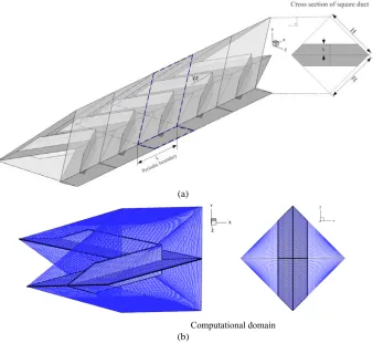
The square duct with double sides of the V–baffle inserted diagonally is presented in Fig.1a, while the computational domain is presented in Fig. 1b. The modified V–baffle vortex generators in a square duct are referred from Refs. (Promvonge et al., 2012). The periodic boundaries (Promvonge et al., 2012) which the flow structure and heat transfer behavior profiles repeat itself from one to another module is applied for inlet and outlet of the computation domain. The tested fluid is air enters to the square duct with constant mass flow rate at an inlet temperature, Tin and flow over the V–baffle turbulators. The baffle height, b where
b/H is identified as the blockage ratio, BR. The longitudinal pitch, L or the space between the baffle positioning is set to L = H, L/H is known as the pitch ratio, PR. As the literature reviews above, the flow attack angle of the V–baffle of 30o is used. The use of 30oV–baffle can be
optimized between the augmenting heat transfer (45oV–baffle) and the
reducing of the pressure loss (20oV–baffle). The case studies and the
boundary conditions for this work are as follows table 2 and 3, respectively.
Frontiers in Heat and Mass Transfer
Available at
www.ThermalFluidsCentral.org
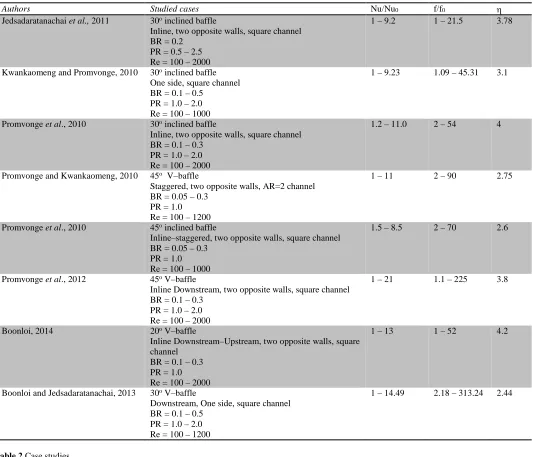
Table 1 The investigations of the vortex generators with numerical method.
Authors Studied cases Nu/Nu0 f/f0 η
Jedsadaratanachai et al., 2011 30o inclined baffle
Inline, two opposite walls, square channel BR = 0.2
PR = 0.5 – 2.5 Re = 100 – 2000
1 – 9.2 1 – 21.5 3.78
Kwankaomeng and Promvonge, 2010 30o inclined baffle
One side, square channel BR = 0.1 – 0.5
PR = 1.0 – 2.0 Re = 100 – 1000
1 – 9.23 1.09 – 45.31 3.1
Promvonge et al., 2010 30o inclined baffle
Inline, two opposite walls, square channel BR = 0.1 – 0.3
PR = 1.0 – 2.0 Re = 100 – 2000
1.2 – 11.0 2 – 54 4
Promvonge and Kwankaomeng, 2010 45o V–baffle
Staggered, two opposite walls, AR=2 channel BR = 0.05 – 0.3
PR = 1.0 Re = 100 – 1200
1 – 11 2 – 90 2.75
Promvonge et al., 2010 45o inclined baffle
Inline–staggered, two opposite walls, square channel BR = 0.05 – 0.3
PR = 1.0 Re = 100 – 1000
1.5 – 8.5 2 – 70 2.6
Promvonge et al., 2012 45o V–baffle
Inline Downstream, two opposite walls, square channel BR = 0.1 – 0.3
PR = 1.0 – 2.0 Re = 100 – 2000
1 – 21 1.1 – 225 3.8
Boonloi, 2014 20o V–baffle
Inline Downstream–Upstream, two opposite walls, square channel
BR = 0.1 – 0.3 PR = 1.0 Re = 100 – 2000
1 – 13 1 – 52 4.2
Boonloi and Jedsadaratanachai, 2013 30o V–baffle
Downstream, One side, square channel BR = 0.1 – 0.5
PR = 1.0 – 2.0 Re = 100 – 1200
1 – 14.49 2.18 – 313.24 2.44
Table 2 Case studies
Configuration BR PR Flow direction Reynolds number
V–baffle placed on thin plate (with plate) 0.1 – 0.3 1 – 2 V–Downstream
V–Upstream 100 – 2000
V–baffle fixed with frame (no plate) 0.1 – 0.3 1 – 2 V–Downstream
V–Upstream 100 – 2000
Table 3 Boundary conditions
Zones Boundary condition
Inlet Periodic boundary
Outlet Periodic boundary
All of the square duct walls - Constant temperature 310K
- No slip wall condition
V–baffle vortex generators Adiabatic wall condition
- Thin plate - Frame
Adiabatic wall condition
(a)
(b)
Fig. 1(a)Square duct with double sides V–baffles taped inserted diagonally and (b) Computational domain.
3. MATHEMATICAL FOUNDATION AND GRID
SYSTEM
The parameters of interest in the current work are the Reynolds number (Re), friction factor (f), Nusselt number (Nu) and Thermal Enhancement Factor (η). The Reynolds number is defined as:
Re=ρuD/µ (1)
The friction factor, f is calculated by pressure drop, ∆p across the periodic module of the square duct, L as:
(
)
2 / f 1 2 p L u ρ ∆ = (2)The heat transfer is measured by the local Nusselt number which can be written as:
Nu x x
h D k
= (3)
The average Nusselt number can be obtained by:
1
Nu Nux A
A
=
∫
∂ (4)The Thermal Enhancement Factor (η) is defined as the ratio of the heat transfer coefficient of an augmented surface, h to that of a smooth surface, h0, at an equal pumping power and given by:
(
) ( )
1/ 30 0
0 0
Nu
Nu / Nu / f/f Nu
pp pp
h h
η= = = (5)
where, Nu0 and f0 stand for Nusselt number and friction factor for the
smooth duct, respectively.
The mathematical foundations are denoted from Refs. (Promvonge et al., 2012). The mathematical model for fluid flow and heat transfer in a square channel was developed under the following assumptions:
• Steady three–dimensional fluid flow and heat transfer • The flow is laminar and incompressible
• Constant fluid properties
• Body forces and viscous dissipation are ignored • Negligible radiation heat transfer
Based on the above assumptions, the tube flow is governed by the continuity, the Navier–Stokes equations and the energy equation. In the Cartesian tensor system these equations can be written as follows:
Continuity equation:
( )
i 0i u x ρ ∂ = ∂ (6) Momentum equation:
(
i j)
i jj i j j i
u u p u u
x x x x x
ρ
µ
∂ = −∂ + ∂ ∂ +∂
∂ ∂ ∂ ∂ ∂ (7)
Energy equation:
(
i)
i j j
T u T
x ρ x x
∂ = ∂ Γ∂
where, Γ is the thermal diffusivity and is given by:
Pr µ
Γ = (9)
Apart from the energy equation discretized by the QUICK scheme, the governing equations were discretized by the second order upwind scheme, decoupling with the SIMPLE algorithm and solved using a finite volume approach (Patankar,1980; Roache, 1998). The solutions were considered to be converged when the normalized residual values were less than 10−5 for all variables, but less than 10−9 only for the energy equation.
The grid system of 180,400 cells was adopted for the current computational model due to the increasing the number of cells result in the different values on both heat transfer and friction factor less than ±0.25% as presented in Table 4 for BR = 0.20, Re = 2000, PR = 1, V– downstream case and with plate
Table 4 Grid system
Grid cell Nu f % error Nu % error f
81,000 40.01121 2.14385 -0.86460 6.53127 120,100 39.99520 2.14511 -0.82424 6.47646 180,400 39.76985 2.28956 -0.25615 0.17876 201,000 39.65485 2.28546 0.03376 0.35751
250,000 39.66824 2.29366 0 0
4. NUMERICAL RESULTS AND DISCUSSION
4.1 Validation of smooth duct
The validation of the computational domain is necessary for the investigation with the numerical methods. The verifications for both heat transfer and friction factor are studied by comparison with the previous values (Incropera and Dewitt, 2006) under a similar operating condition. The results shows agree well within ±0.15% on both heat transfer and friction factor in terms of Nu and f, respectively.
4.2 Flow topology and heat transfer characteristic of V–
baffle with thin plate
The flow structures and heat transfer characteristics in a square duct with 30o V–baffle inserted diagonally (with plate), are present in Figs. 2
– 4. The flow configurations are displayed in term of streamlines in transverse planes while the heat transfer is presented in forms of temperature contours in transverse planes and the Nux contour.
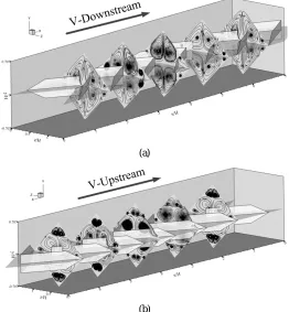
Figs. 2a and b show streamlines in transverse planes (module/4) for V–Downstream and V–Upstream, respectively, for BR = 0.2, PR = 1 and Re = 800. As seen, the flow structure is appeared which consist four main vortex flows and small vortices at the corner of the square duct on both V–Downstream and V–Upstream cases. Considering at the lower part of the streamlines plane, the counter rotating vortex flows with common-flow-down and common-flow-up are induced for V– Downstream and V–Upstream, respectively. The core of the vortex flows is changed depending on the position of the V–baffle. The vortex flows recurrence as one to another module, so, the first plane and the fifth plane are similar flow profiles for both cases.
Figs. 3a and b display the temperature contours in transverse planes (module/4) for V–Downstream and V–Upstream, respectively, for BR = 0.2, PR = 1 and Re = 800. There are found that the use of vortex generators can help with mixing the temperature between the core of the duct and near the wall regimes. The V–Downstream case provides better mixing than the V–Upstream case. The blue contours, the temperature ≅ 300K, are clearly seen at the upper and lower corners of the V–Upstream case due to the jet flows of the V–Upstream case can’t induce in these regimes. The heat transfer phenomena’s are related to the flow configuration part
(a)
(b)
Fig. 2 Streamlines in transverse planes for double sides of 30o V–
baffle inserted diagonally (with plate) (a) V–Downstream and (b) V–Upstream at BR = 0.2, PR = 1 and Re = 800.
(a)
(b)
Fig. 3 Temperature contours in transverse planes for double sides of 30o V–baffle inserted diagonally (with plate) (a) V–Downstream
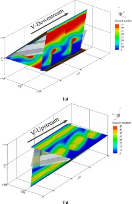
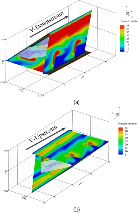
The heat transfer characteristics are also presented in Figs. 4a and b, in term of the Nusselt number contours on the duct walls for V– Downstream and V–Upstream, respectively, at BR = 0.2, PR = 1 and Re = 800. There are found that the use of V–baffle give higher heat transfer rate than the smooth duct for all cases. The V–Downstream performs higher heat transfer rate than the V–Upstream. The peaks of heat transfer areas are appearing, except for the small regimes at the duct corners.
(a)
(b)
Fig. 4 Nux contours in transverse planes for double sides of 30o V–
baffle inserted diagonally (with plate) (a) V–Downstream and (b) V–Upstream at BR = 0.2, PR = 1 and Re = 800.
4.3 Flow topology and heat transfer characteristic of V–
baffle with no plate
As the pre-results, it is found that the use of V–baffle inserted diagonally in a square channel gives very enlarge pressure in comparison with the vortex generators which placed on the walls and also higher than the smooth square duct with no vortex generators. The new design for reducing the pressure loss in the heat exchange duct system is presented with changed the thin plate as a frame (no plate). The streamlines in transverse planes, temperature contours and Nux contours are presented as Figs. 5, 6 and 7, respectively.
As seen, the flow configurations and heat transfer characteristics are similar profile as V–baffle with plate case, but the V–Upstream case of no plate seems to be the higher heat transfer rate than with a plate when considering at the Nux contours in Fig. 7b
(a)
(b)
Fig. 5 Streamlines in transverse planes for double sides of 30o V–
baffle inserted diagonally (no plate) (a) V–Downstream and (b) V–Upstream at BR = 0.2, PR = 1 and Re = 800.
(a)
(b)
Fig. 6 Temperature contours in transverse planes for double sides of 30o V–baffle inserted diagonally (no plate) (a) V–Downstream
(a)
(b)
Fig. 7 Nux contours in transverse planes for double sides of 30o V–
baffle inserted diagonally (no plate) (a) V–Downstream and (b) V–Upstream at BR = 0.2, PR = 1 and Re = 800.
4.4 Performance Evaluation
The performance evaluations of the 30o V–baffle vortex generators
inserted diagonally are presented in terms of Nu/Nu0, f/f0 and η as Figs.
8 – 13. The effects of Reynolds number, blockage ratio and the pitch ratio on both V–Downstream and V–Upstream are investigated. In general, the rising BR and Reynolds number result in the increasing heat transfer rate and the friction factor while the increasing PR leads to the reducing trends on both heat transfer and friction factor values.
For 30o V–baffle with plate, there are found that the increasing rate
of the heat transfer for V–Downstream provides higher than the V– Upstream, especially, the BR > 0.1. The Nu/Nu0 values are around 2 –
20 and 2 – 11 times over the smooth square duct for V–Downstream and V–Upstream, respectively. This means that the maximum heat transfer for V–Downstream is higher than the V–Upstream around 2 times. The f/f0 value, the V–Downstream performs the highest friction
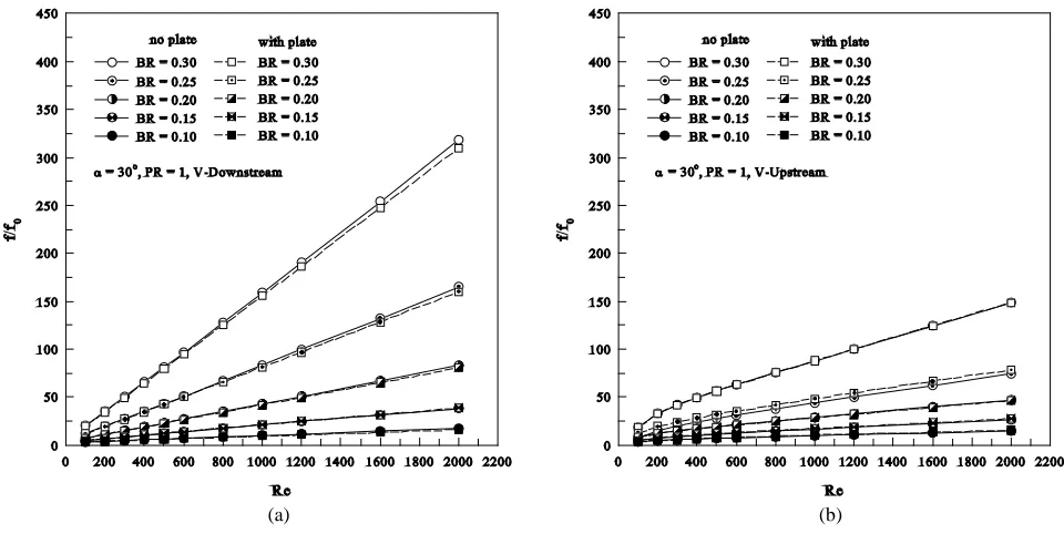
factor than the V–Upstream around 2 times at BR = 0.3, Re = 2000 and PR = 1. The f/f0 values are around 1 – 320 and 1 – 150 times above the
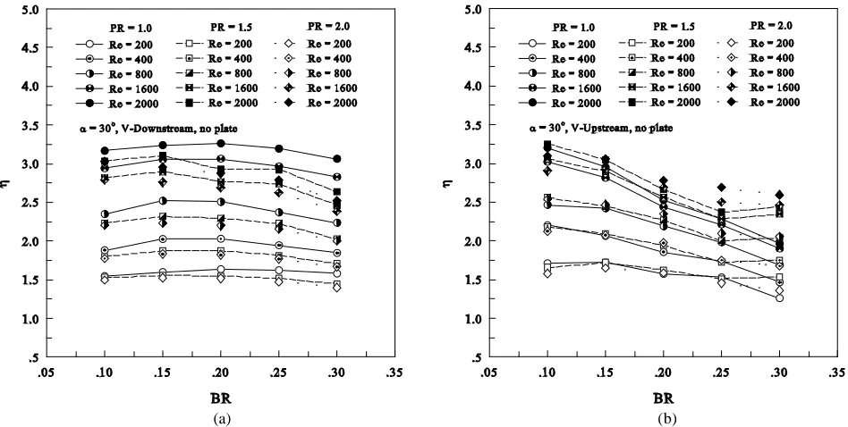
smooth duct with no vortex generators for V–Downstream and V– Upstream, respectively. The peak range for the increasing friction factor is found at 0.25 < BR < 0.30. The thermal enhancement factor, η, is found to be maximum at BR = 0.15 and PR = 1 around 3.2 on the highest Reynolds number for V–Downstream while around 2.75 at the lowest BR, PR = 1 for V–Upstream.
For 30o V-baffle no plate, the Nu/Nu
0 is around 2 – 21 and 2 –
12.5 times higher than the smooth duct with no vortex generators for V–Downstream and V–Upstream, respectively, while the f/f0 is about 1
– 320 and 1 – 150 times over the smooth duct. The optimum thermal enhancement factor is about 3.25 in both cases with the differential case. The V–Downstream performs the maximum thermal enhancement factor at BR = 0.2 and PR = 1, while the V–Upstream performs maximum point at BR = 0.1 and PR = 1.5, at the highest Reynolds number.
Figs. 14 – 15 show a comparison between with plate and no plate cases for Nu/Nu0, f/f0 and η, respectively, at PR = 1. As seen, there are
notices that the heat transfer and friction factor values are nearly values on both cases. This means that the aim to reduce the pressure loss by changing thin plate as a wire frame to installing the V–baffle is not beneficial, but can help to increase the thermal enhancement factor for V–Upstream cases, from 2.75 to 3.25.
(a) (b)
Fig. 8 The variations of Nu/Nu0 with BR values at various PR and Re values for 30o V–baffle inserted diagonally (with plate) for (a) V–Downstream
(a) (b)
Fig. 9 The variations of f/f0 with BR values at various PR and Re values for 30o V–baffle inserted diagonally (with plate) for (a) V–Downstream and
(b) V–Upstream.
(a) (b)
Fig. 10The variations of η with BR values at various PR and Re values for 30o V–baffle inserted diagonally (with plate) for (a) V–Downstream and
(a) (b)
Fig. 11The variations of Nu/Nu0 with BR values at various PR and Re values for 30o V–baffle inserted diagonally (no plate) for (a) V–Downstream
and (b) V–Upstream.
(a) (b)
Fig. 12 The variations of f/f0 with BR values at various PR and Re values for 30o V–baffle inserted diagonally (no plate) for (a) V–Downstream and
(a) (b)
Fig. 13 The variations of f/f0 with BR values at various PR and Re values for 30o V–baffle inserted diagonally (no plate) for (a) V–Downstream and
(b) V–Upstream.
(a) (b)
(a) (b)
Fig. 15 Comparisons of with plate and no plate cases in term of f/f0 with Re values (a) V–Downstream and (b) V–Upstream.
(a) (b)
Fig. 16 Comparisons of with plate and no plate cases in term of η with Re values (a) V–Downstream and (b) V–Upstream.
Table 5 Empirical correlations for 30o V–baffle inserted diagonally
Case Empirical correlation Eq. no. Using range
V–Downstream with plate
0.551 0.4 5.347 0.576 0
Nu / Nu =0.117 Re Pr (BR+1) (PR+1)−
0.777 14.344 0.841
0
f / f =0.026 Re (BR+1) (PR+1)−
(10)
(11)
α = 30o
BR = 0.1 – 0.3 PR = 1 – 2 Re = 100 – 2000 V–Upstream
with plate
0.484 0.4 3.012 0.329 0
Nu / Nu =0.185 Re Pr (BR+1) (PR+1)−
0.625 11.011 0.834
0
f / f =0.092 Re (BR+1) (PR+1)−
(12)
(13)
V–Downstream with no plate
0.550 0.4 4.513 0.538 0
Nu / Nu =0.147 Re Pr (BR+1) (PR+1)−
0.806 14.816 0.875
0
f / f =0.020 Re (BR+1) (PR+1)−
(14)
(15)
V–Upstream with no plate
0.462 0.4 2.319 0.148 0
Nu / Nu =0.243Re Pr (BR+1) (PR+1)−
0.647 11.457 0.779
0
f / f =0.073Re (BR+1) (PR+1)−
(16)
5. CONCLUSIONS
The fully developed periodic laminar forced convection in a heat exchanger square channel with 30o V–baffles inserted diagonally is
investigated numerically in three dimensional. The use of the inserted vortex generators types can help to install and maintenance in the heat exchanger square duct system. The effects of blockage ratio, pitch ratio, Reynolds number, flow direction and the vortex generators configurations are presented. The conclusions of this work are as follows:
- The use of the diagonally inserted vortex generators can help to increase heat transfer rates and the thermal performance but also increase the pressure loss in the heat transfer system.
- The increasing BR, Reynolds number with reducing PR, produce a higher heat transfer rate and friction factor for all cases. The V– Downstream case performs higher heat transfer rate and friction factor than the V–Upstream case.
- In the cases studied, the augmentations are found in ranges 2 – 21 and 1 – 320 times for heat transfer and friction factor, respectively, for 30o V–baffle inserted diagonally in the square channel. The
optimum thermal enhancement factor is around 3.25 for V– Downstream case.
- The different installation methods, placing on the thin plate and inserted with a wire frame, it is found that the wire frame (no plate) is not beneficially for reducing the pressure loss. In both cases, the heat transfer rate and pressure loss values are very nearly values, but the use of the wire frame can help to improve the thermal performance for V–Upstream case.
- The empirical correlations for diagonally inserted vortex generators are presented as table. 5.
ACKNOWLEDGEMENTS
The funding of this study is supported by King Mongkut’s University of Technology North Bangkok, Thailand. The author would like to thanks Dr.Withada Jedsadaratanachai and Assoc. Prof. Dr.Pongjet Promvonge, KMITL for the suggestions
NOMENCLATURE
A heat transfer area, m2
BR blockage ratio, (b/H) b baffle height, m
H hydraulic diameter of square duct f friction factor
GCI grid convergence index
h convective heat transfer coefficient, W m-2 K-1
k thermal conductivity, W m-1 K-1
L cyclic length of one cell (or axial pitch length, H), m Nu Nusselt number
p static pressure, Pa Pr Prandtl number PR pitch ratio, L/H Re Reynolds number T temperature, K
ui velocity in xi-direction, m s-1
u mean velocity in channel, m s-1
Greek letter
µ dynamic viscosity, kg s-1m-1
Γ thermal diffusivity
α rib inclination angle or angle of attack, degree η thermal enhancement factor
ρ density, kg m-3
Subscript
in inlet
0 smooth duct
w wall
pp pumping power ref reference
REFERENCES
Boonloi, A., and Jedsadaratanachai, W., 2013, “3D Numerical study on laminar forced convection in V–baffled square channel,” American Journal of Applied Sciences, 10, 1287 – 1297.
http://dx.doi.org/10.3844/ajassp.2013.1287.1297
Boonloi, A., 2014, “Effect of Flow Attack Angle of V–Ribs Vortex Generators in a Square Duct on Flow Structure, Heat Transfer, and Performance Improvement,” Modelling and Simulation in Engineering, Article ID 985612, 11 pages.
http://dx.doi.org/10.1155/2014/985612
Chen, TY., and Shu, HT., 2004, “Flow Structures and Heat Transfer Characteristics in Fan Flows with and without Delta-wing Vortex Generators,” Experimental Thermal and Fluid Science, 28, 273 – 282.
http://dx.doi.org/10.1016/S0894-1777(03)00107-9
Gentry, MC., and Jacobi, AM., 1997, “Heat Transfer Enhancement by Delta–wing Vortex Generators on a Flat Plate: Vortex Interactions with the Boundary Layer,” Journal of Experimental Thermal and Fluid Science, 14, 231 – 242.
http://dx.doi.org/10.1016/S0894-1777(96)00067-2
Incropera, F., and Dewitt, P.D., 2006, Introduction to heat transfer, 5rd
ed., John Wiley & Sons, Hoboken, NJ.
Jedsadaratanachai, W., Suwannapan, S., and Promvonge, P., 2011, “Numerical study of laminar heat transfer in baffled square channel with various pitches,” Energy Procedia, 9, 630 – 642.
http://dx.doi.org/10.1016/j.egypro.2011.09.073
Joardar, A., and Jacobi, AM., 2005, “Impact of Leading Edge Delta-wing Vortex Generators on the Thermal Performance of the Flat Tube, Louvered-fin Compact Heat Exchanger,” International Journal of Heat and Mass Transfer, 48, 1480 – 1493.
http://dx.doi.org/10.1016/j.ijheatmasstransfer.2004.10.018
Kwankaomeng, S., and Promvonge, P., 2010, “Numerical prediction on laminar heat transfer in square duct with 30° angled baffle on one wall,” International Communication in Heat and Mass Transfer, 857 – 866.
http://dx.doi.org/10.1016/j.icheatmasstransfer.2010.05.005
Li-Ting, T., Ya-Ling, H., Yong-Gang, L., and Wen-Quan, T., 2009, “Numerical Study of Fluid Flow and Heat Transfer in a Flat-plate Channel with Longitudinal Vortex Generators by Applying Field Synergy Principle Analysis,” International Communications in Heat and Mass Transfer, 36, 111 – 20.
http://dx.doi.org/10.1016/j.icheatmasstransfer.2008.10.018
Patankar, S.V., 1980, Numerical heat transfer and fluid flow, McGraw– Hill, New York.
Promvonge, P., Jedsadaratanachai, W., and Kwankaomeng, S., 2010, “Numerical study of laminar flow and heat transfer in square channel with 30o inline angled baffle turbulators,” Applied Thermal
Engineering, 30, 1292 – 1303.
http://dx.doi.org/10.1016/j.applthermaleng.2010.02.014
Promvonge, P., and Kwankaomeng, S., 2010, “Periodic laminar flow and heat transfer in a channel with 45° staggered V–baffles,” International Communication in Heat and Mass Transfer, 37, 841 – 849.
Promvonge, P., Sripattanapipat, S., and Kwankaomeng, S., 2010, “Laminar periodic flow and heat transfer in square channel with 45o
inline baffles on two opposite walls,” International Journal of Thermal Sciences, 49, 963 – 975.
http://dx.doi.org/10.1016/j.ijthermalsci.2010.01.005
Promvonge, P., Jedsadaratanachai, W., Kwankaomeng, S., and Thianpong, C., 2012, “3D simulation of laminar flow and heat transfer in V–baffled square channel,” International Communication in Heat and Mass Transfer, 39, 85 – 93.
http://dx.doi.org/10.1016/j.icheatmasstransfer.2011.09.004
Roache, P.J., 1998, Verification and Validation in Computational Science and Engineering, Hermosa Publishers, Albuquerque, NM, ISBN 0913478083.
Wu, JM., and Tao, WQ., 2012, “Effect of Longitudinal Vortex Generator on Heat Transfer in Rectangular Channels,” Applied Thermal Engineering, 37, 67 – 72.