INTRODUCTION
The process of manufacturing machine com-ponents consists of a series of successive tech-nological operations. Cutting is one of the first operations, from which the technological process of manufacturing the given element is usually started. The division of material can be done by mechanical means, e.g., cutting with scissors or presses, or with thermal methods, which should include plasma cutting, water-abrasive jet cutting, or with oxygen and laser [5].
Laser cutting is a material division technol-ogy, which has been successfully used since the 70s of the XX century. The advantages of this cutting method includes the lack of direct impact through crushed material, on the material cut, with a narrow cutting gap with a minimal devia-tion and even cutting area, ease of automadevia-tion and robotic cutting process and a broad range of applications. The weaknesses and limitations of the laser cutting technology include: maximal
thickness of materials cut limited to 20 – 25 mm, structural changes in the material, resulting in changes in the mechanical properties of structural elements and special requirements regarding the surface condition, chemical condition and physi-cal properties of the materials cut [13, 14].
The course of the laser cutting process and the quality of the final product directly depend on the process parameters, such as: radiation modes, beam parameter product, type of cutting gas, di-ameter of the gas supplying nozzle, beam diam-eter in the focus, focus location and cutting speed. The quality and accuracy of the cut parts also af-fects the stability of the machine tool, as well as the properties of the material cut, in particular the absorption and thermal conductivity [4 – 6, 10].
Quality assessment of the edges and the sur-face after laser cutting is expressed by the follow-ing characteristic values based on the PN-EN ISO 9013: 2017 – 04 standard: rectangular tolerance or inclination of the cutting surface – u, average height of the cutting surface profile – Rz5, reduc
-STUDYING THE EFFECT OF FINISHING WORK ON THE GEOMETRIC ACCURACY OF THE
LASER CUT ELEMENTS
Agnieszka Skoczylas1
1 Lublin University of Technology, Faculty of Mechanical Engineering, Department of Production Engineering,
Nadbystrzycka 36, 20-618 Lublin, Poland, e-mail: [email protected] Research Journal
Volume 12, Issue 1, March 2018, pages 267–272
DOI: 10.12913/22998624/87042 Research Article
ABSTRACT
The article presents the results of geometric accuracy studies of the C45 steel elements after laser cutting, and then subjected to finishing work. Burnishing and a combined machining and burnishing were applied as finishing works. Geometric accuracy stud-ies of the elements after laser cutting and after finishing work were conducted in ac-cordance with the PN – EN ISO 9013: 2017 – 04 standard. It has been noted that the finishing machining enables the improvement of geometric accuracy of the surface after laser cutting. Machining of elements after laser cutting allows for a reduction of the inclination index of the surface up to 42% with respect to the index value after laser cutting. Finishing milling makes it possible to reduce the surface inclination index more than twice. By performing burnishing of elements after laser cutting and finishing milling, no significant improvement of the element accuracy is obtained. Keywords: laser cutting, geometric accuracy, finishing work
tion of the thickness of the element cut – Δa, cut -ting deviations – n, mel-ting the top edge – r and the occurrence of slag and solid droplets on the lower cutting edge [18].
According to PN-EN ISO 9013: 2017 – 04, the quality of components after thermal cutting can be attributed to the quality class. The division into appropriate groups is based on the character-istic values u and Rz5. The quality of components after laser cutting is divided into 5 classes, where class 1 corresponds to the highest cutting quality, while class 5 is the lowest quality [18]. Referring to the guidelines in this standard [18] it is pro-posed that the quality class 1 was required for cut-ting without further mechanical machining, class 2 – when edges are prepared for arc welding.
Providing a large amount of heat to the ob-ject during laser cutting and deviation of the beam from the intended cutting path leads to the for-mation of the deviation of the contour cutting the element from a particular shape or position of the cutting line.
The are a lot of works in the literature, which concern the problem of the non-perpendicularity of the component surface after laser cutting to the surface of the plate cut.
The authors of the paper [7] have noted that while cutting a 18 mm plate made of S355J2 steel, there is a slight bulge on the cut surface. This is probably caused by the weakening of the laser beam, which, in turn, is somewhat distracted at the lower cutting edge, causing a groove.
During the laser cutting of a 10 mm plate made of stainless steel EN 1.4301, the laser beam, dipping into the material, undergoes devia-tion from the perpendicularity [1]. Depending on the cutting conditions, the deviation is between 0,3 mm and 0,75 mm. Such a deviation causes an increase in the surplus value for subsequent technological operations and indicates the need to conduct the finishing treatment [1]. A similar phenomenon, lack of perpendicularity of the cut-ting contour, also occurs when 10 mm non-alloy steel plates are cut after the thermo-mechanical processing (S700MC) and heat-treated (S690QL) [3]. The value of the surface inclination index af-ter thermal cutting u is approximately 0,11 mm and 0,12 mm [3], which allows to qualify the sur-face to the first class according to PN – EN ISO 9013: 2017 – 04.
The presence of the undesirable phenomenon, which is the deviation of the contour of the re-quired cutting outline, constitutes prerequisites for performing the finishing treatment after laser
cutting. Elimination of the contour cutting error is often done by milling and grinding, which is mainly dedicated for objects with bigger dimen-sions and more complex shapes [1], or by con-trolling the cutting parameters, or introducing appropriate corrections into programs dedicate to laser cutters.
The application of the above solutions does not always allow the achievement of the intended effects, so it is a good idea to undertake research in selecting the right machining process, which will allow for a complete or partial elimination of the contour cutting error with the simultaneous improvement of the stereo-metric and physical properties of the surface layer.
The burnishing , as a finishing machining of machine components [11], allows to reduce the surface roughness [8] and to increase the material share [16]. It is also possible to shape lubricat-ing micro-plates on the burnished surfaces, which will increase the abrasion resistance of these surfaces [2, 12]. During burnishing, the change in the concentration of defects of the crystalline structure often takes place, resulting in compres-sive stresses in the surface layer [17]. The con-sequence of changes in the proprieties of the surface layer due to burnishing is the increased abrasion and fatigue resistance [15]. Brushing, which is a variant of dynamic burnishing, is suc-cessfully used not only to improve the properties of the surface layer, but also to round the edges of the workpiece [9].
Considering the positive effects of burnish -ing, it was considered reasonable to undertake re-search on the use of this machining to improve the geometrical accuracy of the laser cut parts. As a result of burnishing, which is an inoperable treat-ment method, dimensional changes are caused by the following factors: plastic deformations and reduction of surface unevenness, as well as densi-fication and crumbling of the structure [11].
The aim of the study was to evaluate the geo-metric accuracy of the surface of laser cut compo-nents, and then subjected to finishing machining, that is burnishing, as well as the combines milling and burnishing.
METHODOLOGY OF RESEARCH
Amada 3000W of the Amada America Inc. com-pany, using standard cutting parameters (cutting speed v = 1150 mm/min, power P = 2,15 kW, frequency fHz = 1280 Hz, gas pressure 0,06 MPa, focus location +13 mm and oxygen as working gas). Five ways of surface finishing machining have been identified after laser cutting:
• finishing milling,
• centrifugal burnishing,
• inishing milling and centrifugal burnishing,
• burnishing,
• finishing milling and burnishing.
The finishing milling and centrifugal bur -nishing process were carried out on the vertical machining centre FV – 580a. Perimeter milling was done using double–bit flycutter of the Sand -vick company with a diameter of 20 mm with 215880 APKT10 bitts, covered with the TiN coating. The following parameters were used for concurrent milling: cutting depth ap= 0,12 mm, feed per tooth fz = 0,067 mm/tooth, cutting speed
vc = 102 m/min.
During the centrifugal machining, a special burnishing head was the tool used for the treat-ment, with a diameter of 70 mm, which has sym-metrically distributed burnishing beads with a diameter of dk = 6,3 mm, in the amount of zk = 12. The following technological parameters were used during machining: tangential velocity of the burnishing head vg = 1143 m/min, feed rate
vf = 3648 mm/min, cross traverse fp = 0,08 mm and traverse g = 0,5mm. The treatment was car-ried out in the presence of cooling-lubricating Mobile Cut liquid.
Burnishing was performed on a universal lathe C11/MB. A burnisher was used as a tool, consisting of a pressurizing unit and a burnishing element, which was a ball made of silicon nitride (Si3N4) with a diameter of dN = 8 mm. During burnishing, the burnishing power F = 720 N was used, feed rate f = 0,05 mm/r and synthetic oil Mobile Vactra Oil.
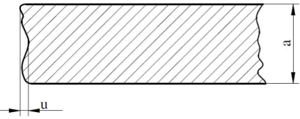
The assessment of the dimensional-shape ac-curacy of laser cut components was performed after the finishing machining, in accordance with PN – EN ISO 9013: 2017 – 04. The u in-dex was used as a characteristic value describing the component quality, determined as the toler-ance of perpendicularity or the inclination of the cutting surface. According to [18], the u index is the distance between two parallel straight lines, between which the profile of the cutting surface is located (fig. 1).
The measurements of the surface inclination index were made using the optical method, based on the surface image analysis after laser cutting, as well as after laser cutting and finishing machin -ing. The 3D digital microscope of the VHX series – 500 of the Keyence company was used for mea-surements, equipped with a digital camera with the ability to enlarge the analysed image from 100 to 1000 times. Figure 2 shows the position used for the measurements. Five samples were tested, on which measurement ware taken five times.
Samples, which were tested, were mounted in a vise bottom surface, which was perpendicular to the laser beam during the cutting process. The digital camera was used for scanning the 2 mm x 8 mm surface at 300 times magnification. Then, with the image analysis software, the contour of the scanned surface and the cutting surface incli-nation index u were determined.
RESEARCH RESULTS
The deviation of the shape from the intended contour, expressed by the inclination of the cut-ting surface, for C45 steel samples after laser cutting is u = 0,184 ± 0,019 mm, and the surface inclination angle after laser cutting 1°24’ ± 0,21’. According to PN – EN ISO 9013, the obtained shape deviation value is a prerequisite for con-ducting mechanical processing. Figure 3 shows the surface deviation from the intended laser cutting contour.
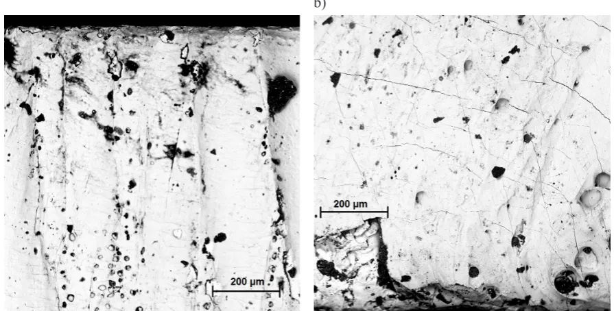
The lower edges of samples are rounded, where the solid material is collected, which con-tributes to the formation of the metal overhang. Micro-cracks are also visible on the cut surface (fig.4a and 4b). The cause of the formation of dis -continuities and micro-cracks is the uneven and rapid cooling of liquid metal on the surface.
Machining with centrifugal burnishing or burnishing after laser cutting allows for a reduc-Fig. 1. The way of the determining u index (u –
a) b)
tion of the surface inclination u (fig. 5). Burnish -ing causes the reduction of the shape deviation by approximately 39% with respect to values after laser cutting. This is probably due to the more in-tense deformation of the striated structure on the surface after laser cutting. In the case of centrifu-gal burnishing, the surface inclination decreased by 42% compared to the u index after laser
cut-ting. The impact energy coming from the burnish-ing head results in an increase in plastic deforma-tions, which translates into a more even contour alignment. The surface contour after the finishing machining is more flattened, and the height differ -ence between the maximum and minimum point of surface point is also partially reduced (fig. 6).
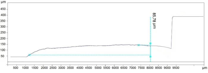
The machining allowed the reduction of the contour error. Cutting with a small cutting depth (ap = 0,12 mm) made it possible to reduce the sur-face inclination index more than twice. The ob-tained value of the index u = 0,08 ± 0,004 mm allows to classify the surface after laser cutting and finishing milling to the first quality class ac -cording to PN – EN ISO 9013: 2017 – 04 (fig. 7). After a combined machining and burnishing, the improvement of the contour accuracy is 29%, for burnishing, and approx. 13% for centrifugal burnishing, with respect to the u index values af-ter laser cutting and finishing milling (fig. 8). The combined machining and burnishing gives posi-tive results in the improvement of the contour ac-curacy. The surface inclination index is smaller from 62% to 68% with respect to the u value after laser cutting.
Fig. 5. Effect of machining type on surface inclination index u
Fig. 7. Surface contour after laser cutting and finishing milling (u = 0,085 mm, bevel angle = 0,61 °)
SUMMARY
This paper analysed the impact of the com-ponent finishing machining on the comcom-ponent geometrical accuracy after laser cutting. The fol-lowing conclusions summarize the results of the performed research:
• during laser cutting, as a result of the laser beam deviation from the intended path, the cutting surface deviation occurs from the in-tended contour, which constitutes prerequi-sites for performing mechanical machining,
• finishing milling allows to reduce the contour error almost twice, which enables the qualifi -cation of the surface to the first quality class according to PN – EN ISO 9013: 2017 – 04,
• the treatment of centrifugal burnishing or bur-nishing for components after laser cutting al-lows to reduce the surface inclination index from 39% to 42% with respect to the index value u after laser cutting,
• by performing a combined machining and burnishing treatment, the value of u index de-creases from approx. 2,5 times to 3,2 times in relation to the surface inclination value after laser cutting.
REFERENCES
1. Feldshtein E., Koman I.: Wycinanie laserowe el-ementów o dużej grubości w blachach ze stali ni-erdzewnej. Przegląd Mechaniczny, 4, 2010, 13–18. 2. Galda L., Dzierwa A., Sep J., Pawlus P.: The ef-fect of oil pockets shape and distribution on seizure resistance in lubricated sliding. Tribology Letters, 37, 2010, 301–311.
3. Górka J., Skiba R.: Wpływ procesów cięcia ter-micznego i strumieniem wody na właściwości i jakość powierzchni ciętych stali niskostopowych o wysokiej granicy plastyczności. Przegląd Spawal-nictwa, 2, 2013, 11–18.
4. Jarosz K., Löschner P., Niesłony P.: Effect of cut-ting speed on surface quality and heat-affected zone in laser cutting of 316L stainless steel. Proce-dia Engineering, 149, 2016, 155–162.
5. Klimpel A.: Technologie laserowe. Wydawnictwo Politechniki Śląskiej, Gliwice, 2012.
6. Kołodzieczak P: Rodzaj cięcia laserowego. Przegląd Spawalnictwa, 7, 2015, 30–33.
7. Krawczyk R., Słania J., Cieśla D.: Porównanie metod cięcia termicznego stali. Przegląd Spawal-nictwa, 7, 2015, 9–14.
8. Kułakowska A., Kukielka L., Kukielka K., Malag L., Patyk R., Bohdal L.: Possibility of steering of products surface layer properties in burnishing rolling process. Applied Mechanics and Materials, 474, 2014, 442–447.
9. Matuszak J., Zaleski K: Edge states after wire bur-nishing of magnesium alloys. Aircraft Engineering and Aerospace Technology, 86 (4), 2014, 328–335. 10. Orishich A.M., Shulyatyev V. B., Golyshev A A.:
The utmost thickness of the cut sheet for the quali-tative oxygen-assisted laser cutting of low-carbon steel. Physics Procedia, 83, 2016, 296–301. 11. Przybylski W.: Technologia obróbki
nagniata-niem. Wydawnictwo Naukowo- Techniczne, Warszawa, 1987.
12. Sep J., Pawlus P., Galda L: The effect of helical groove geometry on journal abrasive wear. Ar-chives of Civil and Mechanical Engineering, 13, 2013, 150–157.
13. Yilbas B. S., Arif A. F. M., Abdul Aleem B. J: Laser cutting of rectangular blanks in thick sheet steel: Effect of cutting speed on thermal stresses. Journal of Materials Engineering and Performance, 19, 2010, 177–184.
14. Yilbas B. S., Shaukat, M. M., Ashraf F.: Laser cut-ting of various materials: Kerf width size analysis and life cycle assessment of cutting process. Optics & Laser Technology, 93, 2017, 67–73.
15. Zaleski K.: The effect of vibratory and rotational shot peening and wear on fatigue life of steel. Eksploatacja i Niezawodność Maintenance and Reliability, 19 (1), 2017, 102–107.
16. Zaleski K., Skoczylas A.: Effect of vibration shot peening parameters upon shapes of bearing curves of alloy steel surface. Advances in Science and Technology Research Journal, 9 (25), 2015, 20–26. 17. Zaleski R., Zaleski K.: Positron annihilation in
steel burnishing by vibratory shot peening. Acta Physica Polonica A, 110 (5), 2006, 739–746. 18. PN- EN ISO 9013:2017 – 04. Cięcie termiczne.
Klasyfikacja ciecia termicznego. Specyfikacja geometrii wyrobu i tolerancje jakości.