Optimizing Engine Start Systems with Application to
Sailing/Coasting and Mild Hybridization
Madhusudan Raghavan
*Propulsion Systems Research Lab, General Motors R&D, Warren, Michigan, USA
Received 25 April 2019; received in revised form 23 June 2019; accepted 20 August 2019 DOI: https://doi.org/10.46604/aiti.2020.4148
Abstract
Engine start systems are key to providing a good customer experience for today’s drivers. Considerable effort
goes into ensuring a smooth and quiet engine start, especially in vehicles equipped with start/stop systems. We
present two novel mechatronic starters that are designed to improve start quality by enabling faster and quieter
engine starts. In the first proposed concept, the traditional alternator is replaced with a motor/generator unit that is
capable of exerting positive torque on the engine as needed, in addition to the conventional power generation
function. The motor/generator is selectively connected to the crankshaft via a selectable geared or belted
connection to enable different operating modes. This starter executes a 400 ms faster start for a typical engine
when compared to a conventional 12V starter. We also present a second starter that uses an integrated two-speed
gear train to crank the engine. The cranking gear ratio is changed from the initial high ratio to a lower ratio once
the engine starts to spin. This ratio change allows the starter motor to continue to operate in a favorable
torque-speed zone and push the engine to a higher pre-ignition rpm than a conventional starter, resulting in a quieter,
smoother start.
We also present results from incorporating the belted/geared starter concept in vehicles with sailing/coasting
mode as well as in mild hybrid propulsion systems. Sailing/coasting mode of operation is enabled by the quick
engine re-start capability of this starter allowing seamless switching between fuelled and unfuelled engine
operation. Such an operation could reduce fuel consumption by about 3-6% on the NEDC driving cycle, without
regenerative braking. One may further hybridize the propulsion system by adding a battery for storing regenerative
braking energy. Using such an architecture, a 6-8% fuel economy improvement on the WLTP certification driving
cycle may be achieved, depending on voltage and power levels implemented, as well as energy storage systems
included.
Keywords: start/stop, mild hybrid, silent start, sailing/coasting
1.
Introduction
Transportation is the source of approximately 25% of Greenhouse Gas (GHG) emissions worldwide. With population
growth and increased energy use and travel, transportation emissions are growing very fast [1]. These include both motor
vehicles and air transport. These GHG challenges are being tackled by the introduction of low carbon fuels, electrification of
the propulsion system, and increased renewable electricity generation from wind and solar. Some of these initiatives are yet
to see widespread adoption due to associated system cost. In this framework, light or mild electrification (under 50V) of the
propulsion system appears to have mass-market potential because of the favorable value proposition ratio it offers. Smooth,
fast engine starts are critical elements of such mild hybrid systems.
*Corresponding author. E-mail address: [email protected]
A start/stop system switches off the engine when the vehicle comes to a stop, thereby eliminating the consumption of
fuel and the release of emissions during engine idling. However, this creates the need for fast engine restart systems to
achieve satisfactory tip-in response when the driver depresses the accelerator to drive away. Reference [2] performs an
assessment of various start/stop systems and investigates the delay in tip-in response and launch performance when the
driver depresses the accelerator when the engine is off. Reference [3] describes experiments to study the difference in
particulate mass emissions for GDI engines with and without start/stop systems. They found that the additional starts with
start/stop systems did not significantly increase the particulate mass emissions. Reference [4] presents a coupled
magnetic-thermal model to study the reason for the damage of the starter motor of a start/stop system of a city bus.
Reference [5] describes the testing of idle-stop systems to see whether real-world fuel savings of such systems are in
line with those predicted by the EPA fuel economy certification cycles. Their results suggest that in many cases the idle stop
systems show minimal benefits on the EPA cycles but deliver considerable fuel savings during real-world operation.
Reference [6] describes a novel start/stop system that injects compressed air into appropriate cylinders in the engine to get
the engine spinning before it is fueled and sparked. They claim that such a system could potentially replace the conventional
starter. Reference [7] studies the operation of engine starts and stops in electrified propulsion systems with a focus on the
effects of engine temperature on engine cranking torques and start-up emissions. They suggest that it may be advisable to
take into consideration engine temperature while crafting engine start/stop strategies. Reference [8] describes advancements
in lead-acid battery technology, in particular, enhanced flooded batteries and absorbent glass mat batteries, driven primarily
by the projected growth in start/stop system market volumes.
Reference [9] quantifies the CO2 potential of start/stop systems by comparing two diesel-powered vehicles in urban
driving conditions. One of them has a conventional propulsion system and the other one has a start/stop system. CO2
reductions of as much as 20% were obtained with the start/stop system. Reference [10] describes a 36V belted alternator
starter system with a 7 kW MGU installed on a 1.9L four-cylinder engine. This enhanced start/stop system delivers 12-14%
fuel economy improvement on the FTP city cycle and about 1% improvement on the FTP highway cycle. Reference [11]
describes the creation of a nonlinear control algorithm to execute smooth stops and restarts on a diesel engine, wherein the
cranking torques are much higher than for a gasoline engine due to the higher compression ratio. Reference [12] describes a
12V belted alternator starter system that can execute engine start/stop functions as well as improve engine responsiveness by
means of torque addition to the driveline during transient maneuvers. Reference [13] investigates various light electrification
architectures ranging from 12V start/stop systems to 48V electrified transmissions, to assess their optimality when applied to
a range of vehicle types and motor/generator locations. Reference [14] investigates engine start quality, NVH, and cranking
speed, and presents experimental data showing that faster cranking is better.
In the present work, we describe two new starter concepts that yield fast, smooth, the engine starts suitable for future
products. We also show how these starters may be integrated into propulsion architectures to yield fuel economy
improvements via sailing/coasting and mild hybridization.
2.
Mechatronic Starter for Geared/Belted Operation
In this section, we describe a novel starter system with unique functional operating characteristics. It is created by
replacing the traditional alternator with a Motor/Generator Unit (MGU) of approximately the same physical size. This MGU
may be used to perform the engine starting functions. Since the alternator interacts with the crankshaft via the accessory belt,
the MGU can also interact with the crankshaft via this same belt. We include a dual tensioner on this accessory belt as the
MGU exerts a negative torque while generating electricity and a positive torque while executing engine starts or driveline
torque boosting. The dual tensioner ensures proper belt operation under these different operating conditions. For situations
to retain the services of a geared conventional starter. However, with an innovative mechatronic arrangement, we may
potentially eliminate this conventional starter by making the MGU play the role of a geared starter. Such an arrangement is
shown in Fig. 1, with the mechatronic device of interested being indicated by the dashed rectangle.
Fig. 1 Engine with a geared/belted mechatronic starter
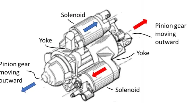
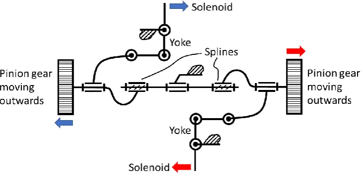
It is shown in considerably more detail in Fig. 2 and in a kinematic diagram format in Fig. 3. It is comprised of 2
solenoids which act on yokes, causing a pair of pinion gears to move outwards. As indicated via the red and blue color
coding, the solenoids cause their respective pinions to move outwards when actuated, assisted by the lever action of the
yokes. When the solenoids are not energized the pinions return to their default positions via return springs. The pinions are
mounted on a splined shaft, so they rotate with the shaft but can also translate axially relative to the shaft, as dictated by the
solenoids. This translation is coupled with a slight rotation due to the spline angle. The shaft with the splines is mounted to
ground (in this case the engine block) via bearings (a revolute joint). The purpose of this mechatronic device is to selectively
connect the MGU to the crankshaft flywheel when needed. The pinion gear on the right (in Fig. 1) engages with a gear
mounted on the MGU. The pinion gear on the left engages with the flywheel which is integral with the crankshaft. Thus, this
arrangement creates a geared connection between the MGU and crankshaft and the MGU can now execute a geared start
similar to the conventional starter. This arrangement thus eliminates the need to carry a conventional starter in addition to the
MGU.
Fig. 2 Mechatronic devices to connect the motor/generator to the flywheel
To avoid an overconstrained system, an electric clutch is introduced between the MGU and accessory belt sprocket.
When the MGU is “geared” to the flywheel, this clutch is opened and the MGU does not exert any torque on the accessory
belt. After the geared engine start is executed, and the solenoids are de-energized, the MGU is no longer connected to the
appropriate. Thus, the mechatronic arrangement of Figs. (2)-(3) enables a selectable geared/belted connection of the MGU to
the crankshaft. When conditions are favorable (moderate temperatures and humidity), the engine start may be executed via
the belt side connection of the MGU to the crankshaft, without having to resort to the geared operation. Since the MGU is
several times more powerful than the traditional 12V starter motor, the engine starts resulting from this geared/belted
arrangement are considerably faster, smoother, and quieter than conventional engine starts. Additional details of the
operation of this motor/generator-based starter device may be found in Reference [14].
Fig. 3 Kinematic diagram of a mechatronic device
3.
Two-Speed Starter System
Next, we describe a two-speed starter that succeeds in squeezing more cranking effort out of a conventional starter
motor. Such motors are typically equipped with a single-speed ratio which is optimized to get the engine turning quickly.
However, due to the shape of the motor’s torque-speed characteristics, the cranking torque drops rapidly as engine rpm
increases. In the proposed invention, we insert a two-speed gearing between the starter motor and the crankshaft flywheel.
Cranking begins with a high torque ratio to get the engine turning. We then switch to a lower torque ratio, so that the motor
can continue to operate in its optimal torque-speed zone and continue to push the engine past its rated pre-ignition rpm.
Typically ignition occurs when the engine has reached 300-400 rpm. The currently proposed system is able to spin the
engine to 700-800 rpm and this results in a smoother start. There are various possible schemes to execute this two-speed
gearset. In our study, we have focused on the use of a Ravigneaux gearset due to its potential compactness resulting from the
shared pinion between adjacent planetary gearsets. Alternatively, layshaft gears and clutches could also be used to execute
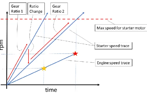
this speed ratio change. Fig. 4 shows the steps entailed in this two-speed engine start. The starter motor begins operation
along the line labeled Gear Ratio 1. The speed ratio change is then executed as shown by the segment labeled Ratio Change.
The starter continues to push the engine, its operation state indicated by the line labeled Gear Ratio 2. Note the engine rpm
line with the yellow and red stars. With a conventional single-speed starter, engine ignition would occur at the yellow star, at
which time the starter motor would have reached its peak rpm. By virtue of the proposed two-speed arrangement, the engine
rpm can reach the red star before ignition, and starter motor rpm would still be within its feasible limits (indicated by the
dashed red line at the top of the figure).
The conventional starter motor generally reaches a maximum output speed of 18000 rpm.when the engine rpm reaches
400 rpm. This translates to a 5:1 ratio for the starter motor gearing, given that the starter pinion to flywheel gear ratio is
approximately 15:135. For our two-speed arrangement, we use the same 5:1 ratio for the first speed and then switch to a
2.5:1 ratio for the second speed. This would allow the engine to reach approximately 800 rpm when the starter motor attains
gear teeth numbers: 𝑁𝑆𝑢𝑛1= 50, 𝑁𝑅𝑖𝑛𝑔1= 200, 𝑁𝑃𝑖𝑛𝑖𝑜𝑛1= 75, 𝑁𝑆𝑢𝑛2= 74, 𝑁𝑃𝑖𝑛𝑖𝑜𝑛2= 30. In our simulations, we
executed the ratio change at 280 rpm engine speed, at approximately the mid-point of the start event. For the purposes of the
simulation, one may note that the engine inertia is 0.1 kg-m2 and the starter rotor inertia is 0.000241 kg-m2. The starter
motor torque begins with a value of approximately 6 N-m at 0 rpm and drops linearly with speed, down to 0 N-m in the
neighborhood of 18000 rpm.
Fig. 4 Engine speed (RPM) with two gear starters
Fig. 5 shows a comparison between the two-speed starter and the conventional single ratio starter. The two-speed starter
is able to crank the engine to approximately 800 rpm while the latter saturates at around 400 rpm. These are unfired
simulations, hence the wavy behavior of the engine rpm after ignition speed is reached. The red, green, and blue traces for
the novel starter result from different assumed actuation times for the speed ratio change (20, 30, and 40 ms respectively),
and thus show the sensitivity to actuator capability. Additional details of the operation of this two-speed starter device may
be found in Reference [15].
Fig. 5 Engine rpm for conventional vs. two-speed starter
4.
Application to Sailing/Coasting and Mild Hybridization
Of the two proposed starter systems, the first one enables a considerably faster start, but with the added cost of the
alternator being replaced by a motor/generator unit. Additionally, a bi-directional tensioner must be added to the front-end
accessory drive belt, in order to allow driveline torque boosting operation as well as belted engine starts. In contrast, the
second proposed starter enables smooth starts by cranking the engine to a higher rpm prior to ignition. In this case, the added
cost is that of the two-speed gearset in place of the single ratio gearset of the conventional starter. The first proposed starter
The terms “sailing” and “coasting” are used interchangeably and refer to the mode of operation when the engine is shut
off and disconnected to minimize engine drag losses during decelerations. This is popular in Europe and China with the high
penetration of manual transmissions. When the engine is decoupled from the driveline during coasting, one possible
operating strategy is to keep the engine running at idle for quick re-engagement to the driveline when the driver demands
acceleration. This idle operation of the engine during coasting continues to use fuel. The proposed first concept in this paper
gets around this problem, as it enables ultra-fast re-starts and thus potentially allows one to maximize the true “engine off”
time periods during coasting, thus maximizing fuel economy. Having a quick start capability allows one to start and
re-connect the engine to the driveline with minimum delay and adequate acceleration response. Coasting may be thought of as a
vehicle transient state between cruising and braking. The various sailing/coasting modes of operation are shown in Fig. 6.
Fig. 6 Sailing/Coasting
A typical driving maneuver is divided into 6 sections or modes. In mode 1, the vehicle is initially stopped (perhaps at a
traffic light) with the engine in Auto Stop mode. In mode 2, the driver releases the brake pedal and depresses the accelerator
pedal. The engine starts and provides torque to accelerate the vehicle as indicated by the linearly increasing speed. Once the
vehicle reaches the desired cruising speed the driver reduces pressure on the accelerator allowing the vehicle to sail/coast in
mode 3. The engine remains on but is disconnected from the driveline. In mode 4, the sailing/coasting operation is continued,
but with the engine disconnected and shut off. In mode 5, the driver depresses the brake pedal to slow the vehicle down as
needed. In mode 6, the vehicle continues to slow down, but with the motor/generator-based starter ready to make a quick
engine re-start in case of a “change of mind” situation, wherein the driver decides to increase speed instead of slowing down
(as when a traffic signal turns green). If this change of mind situation does not occur the vehicle comes to a complete stop at
the end of mode 6.
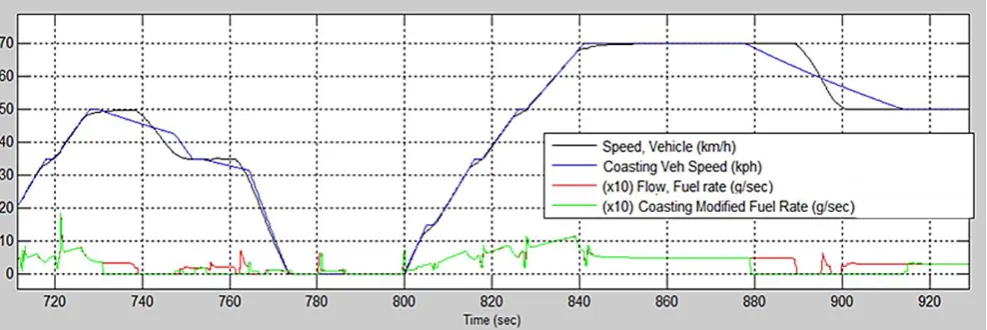
Fig. 7 shows how the sailing/coasting mode may be used to save fuel on a certification driving cycle. The black line
indicates stipulated vehicle speed on the driving cycle. The blue line indicates how the sailing/coasting mode may be used to
approximate the sharp decelerations on the stipulated driving cycle with more gradual coasting maneuvers. This allows one
to save fuel as indicated by the differences between the red curve (fuel rate for stipulated vehicle speed) and the green curve
(fuel rate for the sailing/coasting approximation). Note that the green fuel rate drops to zero during the sailing/coasting
portions while the red curve remains non-zero on these portions. Conservative estimates suggest that this type of
sailing/coasting on the NEDC driving cycle could save about 3-6% of the fuel consumed. This does not require a large
additional battery, as we are not storing any regenerative braking energy for this mode of operation.
We had mentioned earlier the ability of the motor/generator-based starter concept in belted mode to execute super-fast
restarts and thus maximize fuel savings while ensuring adequate acceleration response. Experimental data backing up this
claim are shown in Fig. 8, where we see engine rpm plots for a fired engine start using the motor/generator (blue) and the
conventional starter (red). The engine rpm ramp rate achieved with the motor/generator unit far exceeds that of the
conventional starter, resulting in a 400 ms faster spin up to 550 rpm.
Moving on from sailing/coasting, we can go one step further in mild hybridization by making the additional investment
in a battery for storing regenerative braking energy. This leads to additional fuel economy gains. When the motor/generator
unit of the starter is coupled to a 120 Wh Li-ion battery, such a system, with optimal supervisory powertrain control, can
yield 6-8% of fuel economy improvement on the WLTP driving cycle [12]. Fig. 9 shows simulation plots of cumulative
battery regeneration energy (i.e., a summation of energy flow into the battery) during the WLTP driving cycle, for a 1350 kg.
passenger vehicle equipped with this system. The red curve shows the results of a 12V implementation of such a system and
the blue curve shows a 48V implementation. The grey curve is the vehicle speed trace during the WLTP cycle. Overall,
approximately 1000 to 1200 kJ of regenerative braking energy is captured in the battery during the driving cycle. This
energy, when utilized in the propulsion system to offset 12V electrical loads as well as for driveline torque boosting (i.e.,
exerting electrical torque on the crankshaft via the motor, in place of mechanical torque from the engine), results in the
above-mentioned fuel savings. We have been able to confirm this experimentally on instrumented test vehicles.
Fig. 8 Motor/generator vs. a conventional starter Fig. 9 Cumulative regenerative braking energy into the battery for WLTP
5.
Conclusion
We have described two novel starter concepts. The first one can switch between geared and belted operation. This
integrated starter enables a very fast and smooth start in belt mode compared to a conventional 12V starter. The second
concept uses a two-speed starting device to crank the engine to a higher rpm prior to ignition. It is comprised of an integrated
designs are very comparable and equally applicable to various types of automobiles. The first starter uses two solenoid
actuators and sliding surfaces to move the pinions outwards to execute the belt-to-gear mode changes. The second starter
uses an additional plane of gears and brakes/clutches to execute the speed ratio change during the start. Both require
additional packaging space compared to conventional starters. The first starter is capable of faster starts as the alternator is
replaced by a motor/generator unit with more power capability than a traditional starter motor. Our experiments have shown
that this motor/generator-based starter is about 400 ms faster than a conventional starter.
We have investigated the use of this fast start capability for sailing/coasting operation wherein the engine is
disconnected and shut off during vehicle deceleration. The fast starter allows quick engine re-start and re-connection to the
driveline in response to driver power demand. The use of this sailing/coasting mode of operation could save about 3-6% fuel
on the NEDC driving cycle. Beyond sailing/coasting, one may further increase the level of mild hybridization by adding a
battery for regenerative braking energy storage. In such an architecture, the motor/generator-based starter, in belted mode,
enables hybrid functions such as torque boosting and regenerative braking to achieve a 6-8% improvement in fuel economy
on the WLTP driving cycle.
Conflicts of Interest
The authors declare no conflict of interest.
Table of Notations
APU Auxiliary Power Unit ECU Engine Control Unit ECM
EPA
Engine Control Module Environment Protection Agency EV Electric Vehicle
GHG GDI
Greenhouse Gas
Gasoline Direct Injection
HWFET Highway Fuel Economy Driving Schedule MGU Motor Generator Unit
NEDC New European Driving Cycle NVH Noise, Vibration, Harshness NYCC New York City Cycle SOC State of Charge
UDDS Urban Dynamometer Driving Schedule
WLTP World-Harmonized Light Vehicle Test Procedure
References
[1] D. Greene and S. Plotkin, “Reducing greenhouse gas emissions from U.S. transportation,” Pew Center on Global Climate Change, pp. 1-80, May 2003.
[2] T. Wellmann, K. Govindswamy, and D. Tomazic, “Integration of engine start/stop systems with emphasis on NVH and launch behavior,” in SAE Technical Paper 2013-01-1899.
[3] J. Storey, M. Moses-DeBusk, S. Huff, J. Thomas, M. Eibl, and F. Li, “Characterization of GDI PM during vehicle start-stop operation,” in SAE Technical Paper 2019-01-0050.
[4] Z. Xu, N. Tao, M. Du, T. Liang, and X. Xia, “Damage prediction for the starter motor of the idling start-stop system based on the thermal field,” in SAE International Journal of Commercial Vehicles. 10(2):2017, 2017-01-9181.
[5] J. Wishart, M. Shirk, T. Gray, and N. Fengler, “Quantifying the Effects of Idle-Stop Systems on Fuel Economy in Light-Duty Passenger Vehicles,” in SAE Technical Paper 2012-01-0719.
[6] A. Inglis, R. Timewell, and S. Maskerine, “A novel compressed air starting system,” in SAE Technical Paper 2003-01-2279.
[8] T. Costlow, “Powering up the new stop-start systems,” Automotive Engineering, June 2016.
[9] N. Fonseca, J. Casanova, and M. Valdes, “Influence of the stop/start system on CO2 emissions of a diesel vehicle in urban traffic,” Transportation Research Part D: Transport and Environment, vol. 16, no. 2, pp. 194-200, March 2011. [10] G. Tamai, T. Hoang, J. Taylor, C. Skaggs, and B. Downs, “Saturn Engine Stop-Start System with an Automatic
Transmission,” SAE Transactions, vol. 110, pp. 270-280, 2001.
[11] M. Canova, Y. Guezennec, and S. Yurkovich, “On the control of engine start/stop dynamics in a hybrid Electric vehicle,” ASME Journal of Dynamic Systems Measurement and Control, vol. 131, no. 6, pp. 1-12, November 2009.
[12] M. Raghavan and A. Balhoff, “Electrical torque addition mechanism for engines with high levels of EGR,” in EuCoMeS 2018: Proceedings of the 7th European Conference on Mechanism Science, edited by Burkhard Corves, Philippe Wenger, Mathias Hüsing, 2018, pp. 165-172.
[13] M. Raghavan, “Mild electrification across a spectrum of vehicle types,” in FISITA Technical Paper No. F2018-EHV-009, 2018.
[14] M. Raghavan, N. Bucknor, and V. Donikian, “The kinematics and dynamics of engine start systems,” in IFToMM Asian MMS Conference, Bangalore, 2018.
[15] M. Raghavan, “Novel mechanisms to improve the start quality of automotive engines,” in IFToMM World Congress, Krakow, 2018.
Copyright© by the authors. Licensee TAETI, Taiwan. This article is an open access article distributed under the terms and conditions of the Creative Commons Attribution (CC BY-NC) license