University of New Orleans University of New Orleans
ScholarWorks@UNO
ScholarWorks@UNO
University of New Orleans Theses and
Dissertations Dissertations and Theses
Fall 12-20-2018
Numerical Simulation of Dropped Cylindrical Objects into Water in
Numerical Simulation of Dropped Cylindrical Objects into Water in
Two Dimensions (2D)
Two Dimensions (2D)
Yi Zhen
University of New Orleans, [email protected]
Follow this and additional works at: https://scholarworks.uno.edu/td
Part of the Dynamical Systems Commons
Recommended Citation Recommended Citation
Zhen, Yi, "Numerical Simulation of Dropped Cylindrical Objects into Water in Two Dimensions (2D)" (2018). University of New Orleans Theses and Dissertations. 2568.
https://scholarworks.uno.edu/td/2568
This Thesis-Restricted is protected by copyright and/or related rights. It has been brought to you by
ScholarWorks@UNO with permission from the rights-holder(s). You are free to use this Thesis-Restricted in any way that is permitted by the copyright and related rights legislation that applies to your use. For other uses you need to obtain permission from the rights-holder(s) directly, unless additional rights are indicated by a Creative Commons license in the record and/or on the work itself.
Numerical Simulation of Dropped Cylindrical Objects into Water
in Two Dimensions (2D)
A Thesis
Submitted to the Graduate Faculty of the University of New Orleans in partial fulfillment of the requirements for the degree of
Master of Science in
Mathematics
by
Yi Zhen
M.S. Northwest University, 1999 Ph.D. Northwest University, 2001
ii
Acknowledgements
I would like to take this opportunity to thank my supervisor, Dr. Linxiong Li for his unconditionally sincere support, broad knowledge and scientific guidance. His patience, kindness, professional attitude toward scientific research deeply touch me by heart.
I would like to thank my co-advisor, Dr. Xiaochuan Yu for his helpful discussions, suggestions and guidance on this research. I also would like to thank committee member Dr. Jairo Santanilla and express my appreciations for the help from students in Dr. Yu’s research team.
I would like to thank Dr.Tumulesh Solanky, Dr. Kenneth Holladay, Dr.Ralph Saxton and all Professors in the Mathematics Department at UNO. Their fantastic and brilliant mathematics lectures nurtured my ability and built my confidence in tackling the mathematical problems.
iii
Table of Contents
List of Figures...iv
Abstract...vii
Chapter 1 Introduction...1
1.1 Background/Literature Review...1
1.2 Objectives of the Study...3
1.2.1 Two-dimensional Trajectory of Dropped Cylindrical Object...3
1.2.2 Non-Dimensional Trajectory of Dropped Cylindrical Object...4
Chapter 2 Numerical Investigation of Trajectory of Dropped Cylindrical Object...5
2.1 Governing Dynamic Equations...5
2.1.1 the surge motion...6
2.1.2 the heave motion...6
2.1.3 the pitch motion...8
2.2 Numerical Results...9
Chapter 3 Non-Dimensional Trajectory of Dropped Cylindrical Object ...26
3.1 Nondimensionalization of Governing Equations...26
3.2 Numerical Results...28
3.2.1 the trailing edge effect...28
3.2.2 the drag coefficient effect...31
3.2.3 the drop angle effect...40
3.2.4 the water depth effect...45
Chapter 4 Summary and Conclusions...54
4.1 Summary of Investigation of Trajectory of Dropped Cylindrical Object ...54
4.2 Summary of Study of Dimensionless Trajectory of Dropped Cylindrical Object...55
4.3 Conclusions...57
References...58
iv
List of Figures
Figure 1. The local and global coordinate systems for dropped cylindrical object
Figure 2. Simulated trajectories of dropped cylinders at drop angle 30o with different trailing
edge
Figure 3. Simulated trajectories of dropped cylinders at drop angle 45o with different trailing
edge
Figure 4. Simulated trajectories of dropped cylinders at drop angle 60o with different trailing
edge
Figure 5. Simulated X-Z plane trajectories with different Cdzat drop angle 30o
Figure 6. Simulated X-Z plane trajectories with different Cdzat drop angle 45o
Figure 7. Simulated X-Z plane trajectories with different values of Cdz at drop angle 60o
Figure 8. Simulated X-Z plane trajectories with different values of Cdxat drop angle 30o
Figure 9. Simulated X-Z plane trajectories with different values of Cdxat drop angle 45
o
Figure 10. Simulated X-Z plane trajectories with different values of Cdxat drop angle 60o, Xt=0.5
Figure 11. Simulated time domain translational motions in Z-direction with different values of
dz
C
Figure 12. Simulated time domain translational motions in Z-direction with different values of
dx
C
Figure 13. Simulated time domain translational motions in Z-direction with various trailing edges of Xt
Figure 14. Simulated X-Z plane trajectories with drop angles from 0o to 90o, Xt=0.0
Figure 15. Simulated X-Z plane trajectories with drop angles from 0o to 90o, Xt=0.3
Figure 16. Simulated X-Z plane trajectories with drop angles from 0o to 90o, Xt=0.4
Figure 17. Simulated X-Z plane trajectories with drop angles from 0o to 90o, Xt=0.5
Figure 18. Simulated dimensionless trajectories of dropped cylinders at drop angle 30o with
different trailing edge
Figure 19. Simulated dimensionless trajectories of dropped cylinders at drop angle 45o with
different trailing edge
Figure 20. Simulated dimensionless trajectories of dropped cylinders at drop angle 60o with
v
Figure 21. Simulated dimensionless X-Z plane trajectories with different Cdzat drop angle 30
o
Figure 22. Simulated dimensionless X-Z plane trajectories with different Cdzat drop angle 45o
Figure 23. Simulated dimensionless X-Z plane trajectories with different values of Cdz at drop
angle 60o
Figure 24. Simulated dimensionless X-Z plane trajectories with different values of Cdx
at drop angle 30o
Figure 25. Simulated dimensionless X-Z plane trajectories with different values of Cdx
at drop angle 45o
Figure 26. Simulated dimensionless X-Z plane trajectories with different values of Cdx
at drop angle 60o, Xt=0.5
Figure 27. Simulated time domain dimensionless translational motions in Z-direction
with different values of Cdz
Figure 28. Simulated time domain dimensionless translational motions in Z-direction
with different values of Cdx
Figure 29. Simulated time domain dimensionless translational motions in Z-direction
with different values of Xt
Figure 30. Simulated dimensionless X-Z plane trajectories with drop angles from 0o to 90o,
Xt=0.0
Figure 31. Simulated dimensionless X-Z plane trajectories with drop angles from 0o to 90o,
Xt=0.3
Figure 32. Simulated dimensionless X-Z plane trajectories with drop angles from 0o to 90o,
Xt=0.4
Figure 33. Simulated dimensionless X-Z plane trajectories with drop angles from 0o to 90o,
Xt=0.5
Figure 34. Simulated dimensionless X-Z plane trajectories at dimensionless water depth
z* =(-0.7,0) ,o =30
vi
Figure 35. Simulated dimensionless X-Z plane trajectories at dimensionless water depth
z* =(-1,0) ,o =30o
Figure 36. Simulated dimensionless X-Z plane trajectories at dimensionless water depth
z* =(-6,0) ,o =30o
Figure 37. Simulated dimensionless X-Z plane trajectories at dimensionless water depth
z* =(-0.7,0) ,o =45o
Figure 38. Simulated dimensionless X-Z plane trajectories at dimensionless water depth
z* =(-1,0) ,o =45o
Figure 39. Simulated dimensionless X-Z plane trajectories at dimensionless water depth
z* =(-6,0) ,o =45o
Figure 40. Simulated dimensionless X-Z plane trajectories at dimensionless water depth
z* =(-0.7,0), o =60o
Figure 41. Simulated dimensionless X-Z plane trajectories at dimensionless water depth
z* =(-1,0),o =60o
Figure 42. Simulated dimensionless X-Z plane trajectories at dimensionless water depth
vii
Abstract
The dropped objects are identified as one of the top ten causes of fatalities and serious injuries in the oil and gas industry. It is of importance to understand dynamics of dropped objects under water in order to accurately predict the motion of dropped objects and protect the underwater structures and facilities from being damaged. In this thesis, we study nondimensionalization of dynamic equations of dropped cylindrical objects. Nondimensionalization helps to reduce the number of free parameters, identify the relative size of effects of parameters, and gain a deeper insight of the essential nature of dynamics of dropped cylindrical objects under water. The resulting simulations of dimensionless trajectory confirms that drop angle, trailing edge and drag coefficient have the significant effects on dynamics of trajectories and landing location of dropped cylindrical objects under water.
Keywords:
Dropped cylindrical object, surge-heave-pitch motion, drop angle, trailing edge,
1
Chapter 1 Introduction
Dropped objects are considered as one of top ten hazard accidents in the oil and gas industry and possess potential damage on offshore and onshore facilities [1]. Dropping objects also raise the health and environmental issues in the offshore operation. ABS guidance (2010) [2] suggests a evaluation process for the assessment of damage due to objects dropping from the failed lifting operation on a supply boat or unsecured debris falling overboard during storms. However, the guidance failed to address the problem brought by deep water structures and subsea equipment. One of the main reasons is that people are lack of knowledge of entire trajectory of dropped objects and consequently, the subsequent probability of striking additional structure and equipment and impact on other structure are not able to be estimated. Therefore, it is of importance to understand the fundamental mechanism of motion of objects falling through water including prediction of their landing locations in order to handle the unexpected situation and reduce the harmful impact to minimum level. On this knowledge platform, one would monitor the real-time movement of dropped objects under water, predict landing location on ocean bed and estimate the potential damage occurred. The knowledge would also benefit for proposal of guidance of offshore and onshore operation and minimize damage.
This research work focuses on dropped cylindrical objects which is theoretically treated as slender body and it is largely inspired by the work done by V. Aanesland [3]. Aanesland came up with the theoretical treatment of dropped cylindrical objects based on the similarity between motion of slender cylindrical objects under water and maneuvering of slender ships. He noticed that the coupled surge-heave-pitch motion could be used to describe the motion of dropping slender body. Aanesland performed two model tests in order to compare the theoretical results. In the first model test, two different model-scales were used on dropping objects from a platform deck. From the height of a platform deck, a pipe was dropped above water surface. In the second model test, the angle between pipe and water surface was specified. The pipe was released below the water surface and trajectory was observed. From model test 1, it was shown that drop position has effect on directional stability. The movement of longitudinal is very different from that of lateral direction or heave motion. Model test 2 showed that the effect of angle is significant on motion of longitudinal and lateral directions. Both model tests provide evidence that the viscosity plays an important role in the movement along longitudinal direction or surge motion and there exists similarity between maneuvering of slender ships and moving of dropped pipe through water. Consequently, the equation of motions is formed based on the maneuvering equation as presented by Newman [4].
1.1Background Review
2
water depth and 98% of probability to fall within 50% of water depth. A series of model tests have been performed by Awotahegn [6] to study the trajectory and seabed distribution of two
drill pipes with diameters 8and 12which fall from certain heights above the water surface. The
maximum excursion points and seabed landing points have been identified and analyzed. It was found that simplified method by risk assessment of 2010 is generally conservative [7]. The experimental trajectories of falling cylinders with various mass center, initial velocity and drop angle have been reported [12].
3
A review of the literature regarding the study of dropped objects indicates that considerable experimental, theoretical, and numerical efforts have been made to identify the significant factors for dynamics of dropped cylindrical objects through water and mathematically describe the entire history of dropping from the platform to seabed. Dropped cylindrical objects have been one of the focuses of most of the research papers in the literature due to the explicit mathematical expression of hydrodynamic forces in strip theory and theory of slender body. These mathematical expressions are applied in the dynamic equations to describe the effects of fluid forces- lift and drag and torque generated by fluid forces on the motions.
However, there is a relatively limited amount of research regarding numerical simulation of dimensionless dynamic equations and the nondimensionalization is missing in study of trajectory of dropped cylindrical object under water. The technique of nondimensionalization is widely performed in the fluid mechanics. Nondimensionalization of equation can reduce the number of free parameters. The relative effect of factor can be identified by dimensionless parameters. If term in the equation has large size of certain dimensionless parameters, it implies its importance in the equation for the studied subject. Moreover, nondimensionalized equation helps to gain a greater insight into the relative size of various terms present in the equation and essence of dynamics of motion. Following appropriate selection of scales for the process of nondimensionalization, this could lead to identification of small terms in the equation. Then, one could simplify the complex problem by neglecting the term with smaller impact and retaining the term with large effect. In this way, one could analyze the complexity layer by layer and approach the complex event by adding effects of factors gradually.
1.2 Objectives of the Study
The overall objectives of the present study are to carry out nondimensionalization of the dynamic equations of dropped cylinder under water based on the strip theory and theory of slender body. Dimensionless dynamic equations are used to systematically investigate the effects of trailing edge, drag coefficients, and drop angle. The specific objectives are given below:
1.2.1 Two-dimensional Trajectory of Dropped Cylindrical Object
1) investigate the effect of trailing edge on the simulated trajectory in two-dimensional X-Z plane
2) investigate the effect of x-direction and z-direction drag coefficient on the simulated trajectory in two-dimensional X-Z plane
4
1.2.2 Non-dimensional Trajectory of Dropped Cylindrical Object
1) non-dimensionalizing governing equations of dropped cylindrical object under water
2) investigate the effect of trailing edge on the simulated dimensionless trajectory in two-dimensional X-Z plane
3) investigate the effect of x-direction and z-direction drag coefficient on the simulated dimensionless trajectory in two-dimensional X-Z plane
4) investigate the effect of initial orientation angle on the simulated dimensionless trajectory in two-dimensional X-Z plane
5) investigate the vortices of motion from dimensionless dynamic simulation.
5
Chapter 2 Numerical Investigation of Trajectory
of Dropped Cylindrical Object
2.1 Governing Dynamic Equations
The mathematical expressions of two-dimensional dynamic equations of dropped cylindrical object firstly appeared in Aanesland's research of accidentally falling drilling pipes [3]. Based on the observation of his model tests of dropping pipe through water, it was found that there was similarity between the motion of dropping pipe and maneuvering of slender ships. The slenderness means the length of objects exceed its diameter by a several order of magnitude. For dropped pipe, the length of pipe is far greater than its diameter. Thus, the dropped pipe was theoretically treated as a slender body. During the large part of motion under water, the longitudinal velocity dominates the lateral velocity and the coupled surge-heave-pitch motion of the dropped pipe corresponds to the coupled surge-sway-yaw motion of the ship. Aanesland proposed the two-dimensional dynamic equations of dropped cylindrical object by modifying maneuvering equation of ships as presented by Newman [4].
In order to mathematically describe motion of dropped cylindrical object through water, the two right-handed coordinate systems are adopted which are shown in Figure 1. The upper case letters X and Z denote a global coordinate system. X-axis represents the coordinate of the still-water surface. The Z-axis represents the coordinate along the vertical direction and upward is defined as positive direction. The local coordinate system denoted by lower case letters x and z is fixed on the dropped cylindrical object. The x-axis describes the cylinder axis and origin is defined at the centre of gravity. The local coordinate coincides with global coordinate system where the
cylinder positions horizontally on the water surface. Let denotes the instantaneous angle
between the x-axis of the local coordinate system and the X-axis of the global coordinate system.
z Z
x X
Figure 1 The local and global coordinate systems for dropped cylindrical object
6 2.1.1 the surge motion
The surge motion refers to the motion along x-direction of the local coordinate system. Suppose
instantaneous velocity of dropped object along x-direction is U1, then based on Newton’s
Second Law of Motion, dynamic equation of the surge motion can be written as
FG+Fbuoyancy+Fdrag=mU1
,
where
1
U indicates the derivative with respect to time, FG=mgsin( ) is a component of gravity
along x-direction where m is mass of dropped object and g is gravitational acceleration.
buoyancy
F =gsin( ) is a component of buoyancy along x-direction where is density of water
andis volume of dropped object. Fdrag is drag force (fluid resistive force) occurred when an
object moves through a fluid medium. In this study, the drag force Fdrag=Fform+Fsurfaceincludes
two types of drags, form drag and surface drag. In particular, the form drag is given byFform=
2 1 1 1
| |
8C D U Udx where Cdxis x-direction drag coefficient. The form drag depends on the
cross-sectional area of the cylinder presented to the water and is proportional to velocity squared [18].
The surface drag or skin friction is defined as Fsurface=
2 1 1
0.664U |U | L where is kinematic viscosity and L is length of the dropped object. The surface drag depends on smoothness of surface of the object moving through the fluid. The mathematical expression of surface drag adopted here is an approximation which could be derived from the boundary layer theory for laminar flow [19].
2.1.2 the heave motion
The heave motion refers to the motion along direction in local coordinate system. Suppose
z-direction instantaneous velocity of dropped object is U3, then dynamic equation of heave motion
has the form as following
FG+Fbuoyancy+Fdrag+Flift= ( 3 12)
U U m
where FG=mgcos()is a component of gravity along z-direction, Fbuoyancy=gcos() is a
component of buoyancy along z-direction. The experiments have shown that there exists a drag force caused by a constant current which is proportional to flow velocity squared and the cylinder diameter D. The drag force per unit length of cylinder at x in z-direction is defined as
| ) ( | ) ( 2 1 x U x DU
Cdz z z
where Cdz is z-direction drag coefficient and Uz(x)=U3x2 is
instantaneous velocity along z-direction where 2 is angular velocity of rotation about y-axis.
7
unit length over the length of the dropped cylinder. Thus, the resultant drag force
drag
F = CdzDUz x Uz x dx
L
L ( )| ( )|
2 1 0.5
5 . 0
[20]. Flift refers to lift force which is hydrodynamic forceperpendicular to the surge motion. Lift force is an interaction between the object and fluid
particles that encounter the object. Flift can be approximated by the time rate of change in the
momentum of fluid particles. It is known that the velocity of a fluid particle in z-direction at x is
z U = t z )
cos( -U1sin(),where is angle between velocity of fluid particle and z-axis in the
local coordinate system. When is very small, velocity of a fluid particle Uz at x can be
approximated by Uz=U3x2 where 2 is angular velocity of rotation about y-axis. Then the
differential lift force on the dropped object here is the time derivative of the momentum of water
displaced by object: Flift= m xU x t x
Dt D
z a( ) ( , )]
[
, where ma(x) is mass of water displaced by
cylindrical object at x and ()
Dt D
is material derivative. Thus, we have
( 1 )[ ( )( 3 2)]
m x U x
x U t x F a lift
Assuming the dropped cylindrical object is a rigid body, we obtain
( )( 3 2)
m x U x
x F a lift
+ 1 [ ( )( 3 2)]
x U x m x U a
By theory of slender body, the resultant lift force is
Flift=
nt x
x Fliftdx
= m x U x dx
x U dx x U x m a x x x x a n t n t )] )( ( [ ] )[
( 3 2 1 3 2
=-U1mtU3+U1mtxt2
-
m (x)dxU3n
t x
x a + m x xdx
n
t x
x a( )
2
In this study, 0=m35m53= xm x dx
n
t x
x a( )
since xt xn, then we haveFlift =-U1mtU3+U1xtmt2
-
3 33U
m
wherext represents the coordinate of the trailing edge, xn is the coordinate of the nose,
) ( t
a t m x
m is two-dimensional added mass coefficient for heave direction at the trailing edge,
33
m = nm x dx
t x
x a( )
and m35= nxm x dxt x
x a( )
8 2.1.3 the pitch motion
The pitch motion refers to the rotation about y-axis in local coordinate system. Dynamic equation of pitch motion can be expressed as
drag+lift=
2 55
M
where dragis the torque generated by drag force, liftis the torque generated by lift force, M55is
the moment of inertia in pitch direction and 2 is angular velocity of rotation about y-axis. The
resultant torque of drag force is given by drag=-0.5 L CdzDxUz x Uz x dx
L ( )| ( )|
5 . 0 5 . 0
[20] wheredz
C is z-direction drag coefficient and Uz(x)U3x2 is instantaneous velocity in z-direction.
The mathematical expression of lift is derived as following
lift = nx F dx
t x
x lift
= m x U x dx
x U t x a x x n t )] )( ( )[
( 1 3 2
= nxm x U x dx
t x
x a( )( 3 2)
- m x U x dxx x U x a
x n t )] )( (
[ 3 2
1
= nxm x U x dx
t x
x a( )( 3 2)
- nt x x
x x a x U x
m x
U1 [ ( )( 3 2)]| +U nm x U x dx
t x
x a( )( 3 2)
1
With 0= m35 m53= nxm x dx
t x
x a( )
, we havelift=
m55 2+U1xtmt(U3xt2)+U1m33U3 ,
wherext represents the coordinate of the trailing edge, xnthe coordinate of the nose, mt ma(xt)
is two-dimensional added mass coefficient for heave direction at the trailing edge, m33=
dx x m n t x
x a( )
is added mass for heave motion from strip theory, and m55= x ma x dxx x n t ) ( 2
is added9
After solving for U1 , U3 and 2 in the local coordinate system at each time step, the motions
in the local coordinate system are transformed into the motions in the global coordinate system by using the relationship
[
X
Z]=[U1 U3][
) cos( ) sin( ) sin( ) cos( ]
The instantaneous angle is solved by
=2.
2.2 Numerical Results
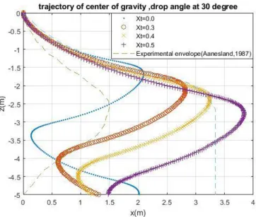
Simulations have been performed through the use of the values Xt=0.0, 0.3, 0.4 , and 0.5 where
Xt=|xt /L| is nondimensional trailing edge position. Figs 2-3 show the resulting trajectories for
the initial orientation angles of 0=30o , 0=45o and 0=60o and corresponding experimental
envelop [3], respectively. For both initial angles, the simulated trajectories at the trailing edge positions Xt=0.3 and Xt=0.4 are more in line with the experimental envelop. Trajectories with Xt=0.5 overshoot the right-hand side boundary of the observed experimental range. All trajectories show a similar pattern. The effect of the trailing edge weakens at a higher initial
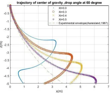
orientation angle 0. Figure 4 shows the simulated trajectories for 0=60o. The simulated
trajectory for Xt=0.4 falls into the range of experimental trajectory. From Figure 2 to Figure 4, it
can be seen that when initial orientation angles increase from 30o to 60o , simulated landing
10
11
12
Figure 4 Simulated trajectories of dropped cylinders at drop angle 60o with different trailing edge
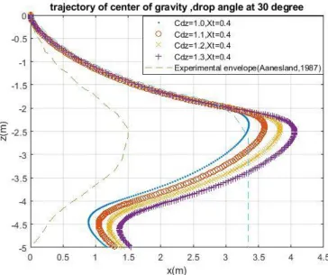
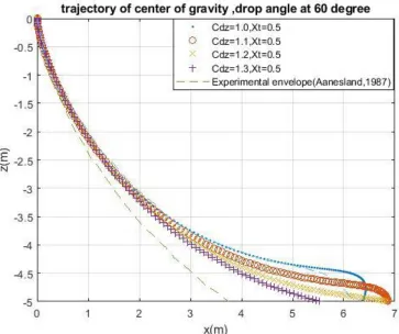
Simulations have been performed through the use of the trailing edge value of Xt=0.4 for initial
orientation angle0=30o and 0=45o and 0.5 for initial orientation angle0=60o . Figs 5-7 show
the resulting trajectories for different z directional drag coefficients, Cdz=1.0, 1.1, 1.2 and 1.3,
respectively.The simulated trajectories at the z directional drag coefficients Cdz=1.0 and 1.1 are
more in line with the experimental results. Figure 5 shows that trajectories with Cdz=1.2 and 1.3
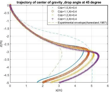
overshoot the right-hand side boundary of the observed experimental range at drop angle 30. At
drop angle of 45, trajectories with Cdz=1.0, 1.1, and 1.2 seem in line with experimental results
which is shown in Figure 6. Increasing drop angle by 60, trajectories with Cdz=1.2 and 1.3 seem
in line with experimental results which can be seen from Figure 7. All trajectories show a similar pattern and a similar landing position within experimental range. From the figures, it can be seen that for each dropping angle, the dropped object demonstrated similar simulated trajectories.
However, the larger drag coefficient Cdz seems to have farther landing point in postitive
x-direction and the larger resistance force slows down the fall allowing the dropped cylinder to
travel further in X-direction. The drag coefficient of Cdz=1.0 reaches a good agreement with the
13
14
15
Figure 7 Simulated X-Z plane trajectories with different values of Cdz at drop angle 60o
The effect of x-direction drag coefficient Cdx on the simulated trajectory in X-Z plane is studied
and shown in Figs 8-10. Simulations have been performed through the use of the values Xt=0.4
for initial orientation angle0=30o and
0
=45o and 0.5 for initial orientation angle
0
=60o . Figs
8-10 show the resulting trajectories for x-directional drag coefficients, Cdx=1.0, 1.1, 1.2 and 1.3,
respectively. From the figures, it can be seen that the simulated trajectories are identical when
drop angles at 30o and 45o. When drop angle increases to 60o, there exists a small deviation of
simulated trajectories at the sea bottom. Overall, the figures indicate that Cdx has insignificant
16
17
18
Figure 10 Simulated X-Z plane trajectories with different values of Cdxat drop angle 60o, Xt=0.5
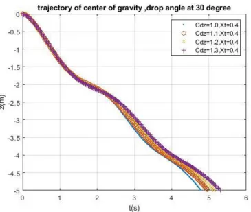
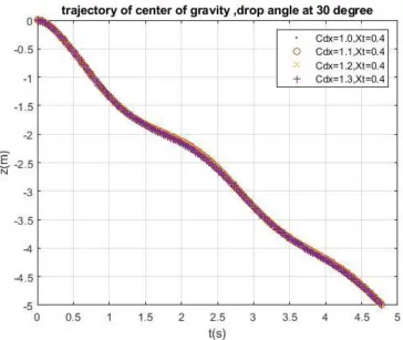
Figure 11 shows time domain translational motions in Z direction for initial orientation angle of
0
=45o with z direction drag coefficients Cdz=1.0, 1.1, 1.2 and 1.3. Translational motions in
Z-direction for x Z-direction drag coefficients Cdx=1.0, 1.1, 1.2 and 1.3 are shown in Figure 12
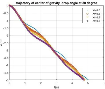
respectively. For Figs 11-12, the trailing edge Xt=0.4 is used. In Figure 13, the simulated translational motions are shown for trailing edge position Xt=0.0, 0.3, 0.4, and 0.5, repectively.
It should be noted that the deviation of trajectories at different z direction drag coefficients Cdz
happens at falling distance of 2 meters. The time domain translational motions seem identical for
various values of the x direction drag coefficient Cdx. In Figure 13, it can be seen that the
19
20
21
Figure 13 Simulated time domain translational motions in Z-direction with different trailing edges of Xt
Simulations have been performed through the use of the trailing edge values of Xt=0.0, 0.3, 0.4 , and 0.5. Figs 14-17 show the resulting X-Z plane trajectories for the initial orientation angles
varying from 0o and 90o in uniform increments of 15o at four different trailing edge values. The z
direction drag coefficient is unchanged with Cdz=1.0. The x direction drag coefficient Cdx=1.2 is
used and As shown in Figures, dropped cylindrical object seem to travel further when the
dropped angle is increased. When drop angle is increased to 90o, X-values tend to decrease to
zero meter. When the trailing edge increase, X-values at drop angle of 90o seems to decrease.
The total excursion distribution at 5 m water is employed in the simulation. Simulated results
confirm that the initial orientation angle 0 is one of the significant factors in determination of
22
23
24
25
Figure 17 Simulated X-Z plane trajectories with drop angles from 0o to 90o, Xt=0.5
26
Chapter 3 Non-dimensional Trajectory of Dropped Cylindrical Object
3.1 Nondimensionalization of Governing Equation
The technique of nondimensionalization is widely performed in the fluid mechanics. nondimensionalization of equation can reduce the number of free parameters. The relative effect of factors can be identified by their dimensionless coefficients. If a factor in the equation has relatively larger dimensionless coefficient, it implies that the factor has relatively larger importance in the equation for the studied subject. Moreover, nondimensionalized equation helps to gain a greater insight into the essential nature of dynamics of motion. Following appropriate selecting of scales for the nondimensionalization process, this could lead to identification of small terms in the dynamic equation. By neglecting the term with smaller impact and retaining the term with large effect, one could simplify the complex problem layer by layer and approach the complete problem by adding complexity gradually. Here, nondimensionalization is carried out for the two-dimensional dynamic equation of dropped cylindrical object and dimensionless dynamic equations are obtained.
Using the equation of surge motion, the units of measurement of the velocity U and time T are obtained. The dynamic equation of surge motion is
(m-)gsin()-0.664 2L U1 |U1|-0.125 Cdx D2U1|U1|=m
1
U
By introducing the unit of measurement of the velocity U and time T, the velocity of surge
motion U1 and time t are expressed as
U1=U
' 1
U
t=T t
where U1 and t are the dimensionless velocity and dimensionless time, respectively. Plugging
the expressions above into equation of surge motion, we have
(m-)gsin()-0.664 2L U1 |U1|U3/2-0.125 Cdx D2U1|U1|U2=m
1 U T U
By dividing by m T U
on both sides of equation, we have
1
U = m m
gsin()
U T
-0.664 2L U1 |U1|U3/2
mU T
-0.125 Cdx D2U1|U1|U2
mU T
By choosing
0.125 D2U2
mU T
=1 and g
U T
27
The unit of measurement of velocity and time in trajectory of dropped cylindrical object are obtained as
U = 8 2
D mg
,
and
T= 8 2
D g
m
By introducing unit of measurement of velocity and time U and T into the dynamic equations of surge, heave and pitch motions, the two-dimensional dynamic equations of dropped cylindrical object under water are nondimensionalized as followings
For Surge Motion:
1
U =A1sin()-B1U1 |U1|-C1U1|U1|
where U1 is dimensionless velocity of surge motion and A1, B1 , and C1 dimensionless
parameters which are expressed as
1
A = m m
,
1
B =0.664 2LU1/2
m T
,
and C1Cdx
For Heave Motion:
3
U =-A2 cos()+B2U32+C222+D2U1U3+E2U1 2
where U3 and 2 are dimensionless velocity of heave motion and dimensionless angular
velocity about y-axis and A2, B2 , C2 and D2 are dimensionless parameters which are
expressed as 2 A = m m m 33 , 2
B =0.5CdzDLUT/(m33m),
2
28 2
D =mtUT/(m33m),
2
E =(xtmt m)/(m33m)
For Pitch Motion:
2=A3U3 2+B3U1U3+C3U1 2
where U1, U3, and 2 are dimensionless velocity of surge motion, heave motion and
dimensionless angular velocity about y-axis, respectively. The dimensionless parameters A2, B2
, C2 and D2 are expressed as
3
A =0.5CdzDL3UT/(m55M55)
3
B =( )( ) /( 55 55) 2
33 xm UT m M
m t t ,
and C3=-xtmt
2
UT/(m55M55).
The length scale L in this study is
LUT = 8 2
D mg 2 8 D g m
= 2
8m
D
The length L is the distance covered in the time interval of T at the velocity U. It provides an estimate of the order of magnitude of the distance at which motion of dropped cylindrical object
stop.
3.2 Numerical Results
3.2.1 the trailing edge effect
Using non-dimensional governing equations of surge, heave and pitch motionsDimemsionless simulations have been performed through the use of the trailing edge values of Xt=0.0, 0.3, 0.4 , and 0.5. Resulting non-dimensional trajectories are shown in Figs 18-20 for the initial orientation
angles of 0=30o,
0
=45o , and
0
=60o , respectively. For both initial angles of
0
=30o and
0
=45o , the simulated dimensionless trajectories at the trailing edge positions Xt=0.3 and
Xt=0.4 are more in line with the experimental results. Dimensionless trajectories with Xt=0.5 overshoot the right-hand side boundary of the observed experimental range. All trajectories show a similar pattern. The effect of the trailing edge decreases at a larger initial orientation
angle 0. Figure20 shows the simulated dimensionless trajectories for 0=60
29
dimensionless trajectory for Xt=0.4 seems to agree well with of dimensionless experimental values. From Figure 18 to Figure 20, it can be seen that when initial orientation angles increase
from 30o to 60o , simulated dimensionless landing points seem to shift to farther landing location
along horizontal direction. Landing positions of the dropped cylindrical at large initial dropping angles seem to separate farther apart compared with those at lower angles. The dimensionless simulation show that the trailing edge position Xt has a significant effect on the simulated dimensionless trajectory.
30
31
Figure 20 Simulated dimensionless trajectories of dropped cylinders at drop angle 60o with different trailing edge
3.2.2 the drag coefficient effect
Non-dimensional simulations have been performed through the use of the values Xt=0.4 for
initial orientation angle0=30
o and
0
=45o and 0.5 for initial orientation angle0=60
o . Figs
21-23 show the resulting non-dimensional trajectories for different z directional drag coefficients,
dz
C =1.0, 1.1, 1.2 and 1.3, respectively. Figure 21 shows that simulated dimensionless trajectory
overshoot at right boundary of experimental envelop for all values of Cdz at drop angle of 30o .
From Figure 22, It can be seen that dimensionless trajectories for Cdz=1.0 and 1.1 are in line
with experimental envelop when the drop angle is increased to 45o. When the drop angle is
increased to 60o , the dimensionless trajectories for Cdz=1.2 and 1.3 seem to fall into the range of
experimental dimensionless trajectory as shown in Figure 23. Overall, it can be seen that for each drop angle, the dropped object demonstrated similar simulated dimensionless trajectories compared with simulation with physical units. It shows that trajectory under the larger drag
coefficient Cdz seems to cause farther landing point in positive x-direction. The possible reason
is that larger Cdz arises larger resistance force which slows down the falling motion and allows
32
33
34
Figure 23 Simulated dimensionless x-z plane trajectories with different values of Cdz at drop angle 60o
The effect of x-direction drag coefficient Cdx on the simulated dimensionless trajectory in X-Z
plane is studied and shown in Figs 24-26. Dimensionless simulations have been performed using
the trailing edge values of Xt=0.4 for initial orientation angle0=30o and
0
=45o and 0.5 for
initial orientation angle0=60o . Figs 24-26 show the resulting dimensionless trajectories for
x-directional drag coefficients, Cdx=1.0, 1.1, 1.2 and 1.3, respectively. From the figures, it can be
seen that the simulated trajectories are identical when drop angles at 30o and 45o. When drop
angle increases to 60o, the small deviation of simulated trajectories appear at the sea bottom.
Overall, dimensionless simulation indicate that Cdx has insignificant effect on the trajectories in
35
36
37
Figure 26 Simulated dimensionless X-Z plane trajectories with different values of Cdxat drop angle 60o, Xt=0.5
Figure 27 shows time domain dimensionless translational motions in Z direction for initial
orientation angle of 0=45
o with z direction drag coefficients
dz
C =1.0, 1.1, 1.2 and 1.3. The
dimensionless translational motions in Z-direction for x direction drag coefficients Cdx=1.0, 1.1,
1.2 and 1.3 are shown in Figure 28 respectively. For Figs 27-28, the trailing edge Xt=0.4 is used. In Figure 29, the simulated dimensionless translational motions are shown for trailing edge position Xt=0.0, 0.3, 0.4, and 0.5, repectively. It can be seen that the deviation of trajectories at
different z direction drag coefficients Cdz happens in middle of falling motion. The time domain
translational motions seem identical for various values of the x direction drag coefficient Cdx. In
38
39
40
Figure 29 Simulated time domain dimensionless translational motions in Z-direction with different values of Xt
3.2.3 the dropping angle effect
Non-dimensional simulations have been performed through the use of the values Xt=0.0, 0.3, 0.4 , and 0.5. Figs 30-33 show the resulting non-dimensional X-Z plane trajectories for the initial
orientation angles varying from 0o and 90o in uniform increments of 15o. The drag coefficient
are unchanged with value of Cdz=1.0 and Cdx=1.2 for simulations. As shown in Figures,
non-dimensional X position tends to increase when increasing the dropped angle. When drop angle
reach 90o, X tends to decrease to zero. When the trailing edge increase, the positive X position
at 90o seems to decrease. The total excursion distribution at non-dimensional z position of 0.7 is
employed in the simulation. Non-dimensional simulated results confirm that the initial
orientation angle 0 is one of the significant factors in determination of shape of trajectories of
41
42
43
44
Figure 33 Simulated dimensionless X-Z plane trajectories with drop angles from 0o to 90o, Xt=0.5
45 3.2.4 the water depth effect
Non-dimensional simulations have been performed under the trailing edge values of Xt=0.0, 0.3, 0.4 , and 0.5. Figs 34-42 show the resulting dimensionless trajectories in X-Z plane for the initial
orientation angles 0=30o, 45o and 60o. For each drop angle, the non-dimensional X-Z
trajectories have been inspected at three non-dimensional Z position of z*=0.7, 1, 6. As shown in Figures, non-dimensional dynamic cycle of motion seems to stop at around 5 which correspond to water depth around 50 meters. This characteristic is failed to captured by simulation with units. From the figures, it can be seen that the non-dimensional trajectory seems to end its spiral motion or periodic mode in deeper vertical position when the dropping angle is increased. In other words, the dropped object with larger dropping angle seem to reach deeper vertical position. The trailing edge seem to cause object to land in farther x position.
46
47
48
49
50
51
52
53
54
Chapter 4 Summary and Conclusions
4.1 Summary of Investigation of Trajectory of Dropped Cylindrical Object
Using two-dimensional governing equations of surge, heave and pitch motions similar to maneuvering of ships, the simulated trajectories of dropped cylindrical object are obtained under various trailing edge positions, drag coefficients and initial orientation angles. In order to investigate the effects of trailing edge on simulated trajectories, numerical simulations have been performed at four trailing edge values of Xt=0.0, 0.3, 0.4 , and 0.5. The resulting simulation show that the trailing edge position Xt has a significant effect on the simulated trajectory and the trajectories at the trailing edge positions Xt=0.3 and Xt=0.4 are more in line with the experimental results. Trajectories with Xt=0.5 agree with experimental envelop for initial
orientation angle is greater than 60o. At small angle, the trajectory overshoots the right-hand side
boundary of the observed experimental range. It implies that there is interaction between trailing edge effect and dropping angle effect. The effect of the trailing edge decreases at a larger initial
orientation angle 0.Overall, All trajectories show a similar pattern. With increasing dropping
angle, simulated landing points seem to shift to further along X-direction. At large initial drop angles, the simulated trajectories seem to separate farther apart. Landing positions of the dropped cylindrical objects are significantly affected by trailing edge position.
In order to exam the effect of z directional drag coefficient on trajectory of dropped cylindrical object, the two-dimensional numerical simulations have been conducted for initial orientation
angles of 0=30o and
0
=45o with the trailing edge at value of Xt=0.4 and Xt=0.5 is used for
initial orientation angle0=60o The resulting trajectories show that z directional drag coefficients
dz
C =1.0 and 1.1 are more in line with the experimental results at drop angle 30. Cdz=1.2 and 1.3
overshoot the right-hand side boundary of the observed experimental range at drop angle 30.
When drop angle increase to 45o, however, trajectories with Cdz=1.1, and 1.2 seem to fall in
experimental envelop. Increasing drop angle by 60o, trajectories with Cdz=1.2 and 1.3 seem to
agree with experimental results. Overall, all trajectories show a similar pattern and a similar landing position within experimental range. It can be seen that for each dropping angle, the
dropped object demonstrated similar simulated trajectories. The larger drag coefficient Cdz
seems to have farther landing point in x-direction.
The effect of x-directional drag coefficient on trajectory of dropped cylindrical object was investigated by two-dimensional(2D) numerical simulations with the trailing edge at value of
Xt=0.4 for initial orientation angle at 0=30o and 0=45o and Xt=0.5 for initial orientation
angle0=60o The resulting trajectories for different x directional drag coefficients show that the
simulated trajectories are identical when drop angles at 30o and 45o. When drop angle increases
to 60o, a small deviation of simulated trajectories exists at the sea bottom. Overall, the figures
55
The effects of z direction drag coefficient, x direction drag coefficient and trailing edge have been examined through time domain translational motions in Z direction. It is shown that the
trajectories deviation occur under various z direction drag coefficients Cdz. The time domain
translational motions seem identical for various values of the x direction drag coefficient. It can also be seen that the trailing edge has significant effect on the entire trajectories of dropped objects from top to bottom. Simulation results confirm that the trailing edge is one of the significant factors in determination of dynamics of dropped objects.
The effect of drop angle on the trajectory was investigated by simulating trajectory for the initial
orientation angles varying from 0o and 90o with unit increments of 15o. Simulations have been
performed under the four trailing edge values of Xt=0.0, 0.3, 0.4 and 0.5. The drag coefficient
were chosen as Cdz=1.0 and Cdx=1.2. Simulated trajectories were significantly affected by drop
angle. When the trailing edge increase, the positive X position at 90o seems to decrease. The
trajectory of dropped cylinder demonstrate different patterns and simulated results confirm that
the initial orientation angle 0 is one of the significant factors in determination of shape of
trajectories of dropped cylindrical object as well as trailing edge.
4.2 Summary of Study of Dimensionless Trajectory of Dropped Cylindrical Object
The dimensionless dynamic equations of dropped cylindrical object under water were obtained by performing the technique of nondimensionalization on governing equations. Dimensionless numerical simulations have been performed on trajectory of dropped cylindrical object at various values of trailing edge Xt=0.0, 0.3, 0.4 , and 0.5 which is position of trailing edge. Using dimensionless governing equations of surge, heave and pitch motions similar to maneuvering of ships, the resulting dimensionless trajectories were obtained for the initial orientation angles of
0
=30o, 45o,and
0
=60o , respectively. The dimensionless simulation show that the trailing edge
position Xt remains a significant effect on the simulated trajectory. The simulated results show that the dimensionless trajectories at the trailing edge positions Xt=0.3 and Xt=0.4 are more in line with the experimental results. Dimensionless trajectories with Xt=0.5 overshoot the right-hand side boundary of the observed experimental range. All dimensionless trajectories show a similar pattern. There is coupled effect between trailing edge effect and dropping angle effect.
For 0=60o, the dimensionless trajectory agrees with experimental range at higher value of
trailing edge position 0.5. When dropping angle is increased, simulated landing position seem to shift to farther landing location along horizontal direction.
The effect of z directional drag coefficient on trajectory of dropped cylindrical object is
examined. The resulting dimensionless trajectories for different z directional drag coefficients
show that z directional drag coefficients Cdz=1.0 and 1.1 are more in line with the experimental
results at drop angle 30. When drop angle increase to 45o, trajectories with Cdz=1.0, 1.1, and 1.2
seem to fall in experimental envelop. Increasing drop angle by 60o, trajectories with Cdz=1.2 and
56
similar landing position within experimental range. The larger drag coefficient Cdz seems to
have farther landing point in x-direction. The larger Cdz causes the larger resistance force and
slows down the falling motion.
The effect of X- directional drag coefficient on dimensionless trajectory of dropped cylindrical object was investigated by numerical simulations using the trailing edge at value of Xt=0.4 for
initial orientation angle at 0=30o and 0=45o and Xt=0.5 for initial orientation angle0=60o .
The resulting dimensionless trajectories show that the simulated trajectories are identical when
drop angles at 30o and 45o. When drop angle increases to 60o, there exists a small deviation of
simulated trajectories at the sea bottom. Overall, the figures indicate that Cdx has insignificant
effect on the trajectories in X-Z plane.
Time domain dimensionless translational motions in Z direction are obtained under various z
direction drag coefficients Cdz=1.0,1.1,1.2 and 1.3, various x direction drag coefficients
dx
C =1.0, 1.1, 1.2 and 1.3, and various trailing edge position Xt=0.0,0.3,0.4, and 0.5,
respectively. It is shown that the dimensionless trajectories exhibit different path at different trailing edges and at different z direction drag coefficients. The x direction drag coefficient does not have significant impact on the trajectories along z direction. The trailing edge has effect on the evolution of trajectories of dropped objects from top to bottom. Dimensionless simulated results confirm that the trailing edge is one of the significant factors in determination of dynamics of dropped objects under water.
The effect of drop angle on the dimensionless trajectory was examined by simulating trajectory
for the initial orientation angles varying from 0o and 90o in uniform increments of 15o.
Simulations have been performed under the trailing edge at the values of Xt=0.0, 0.3, 0.4 and
0.5. The drag coefficient are unchanged with value of Cdz=1.0 and Cdx=1.2 during simulation.
Dimensionless simulated trajectories show that when drop angle reach 90o, X tends to decrease
to zero. When the trailing edge increase, the positive X position at 90o seems to decrease. The
dimensionless trajectory of dropped cylinder demonstrate different patterns and simulated results
confirm that the initial orientation angle 0 is one of the significant factors in determination of
shape of trajectories of dropped cylindrical object as well as trailing edge. Moreover, dimensionless at large initial dropping angles seem to separate farther.
In order to investigate the number of oscillation of motion, non-dimensional simulations have been performed through the use of the values Xt=0.0, 0.3, 0.4 , and 0.5. The resulting
non-dimensional X-Z plane trajectories for the initial orientation angles 0=30
o, 45o and 60o in
uniform increments of 15o. For each drop angle, the non-dimensional x-z trajectories have been
57
to stop its oscillation mode at deeper vertical position. The trailing edge seem to cause object to land in farther x position.
4.3 Conclusions
In this study, the nondimensionalization is carried out for the two-dimensional coupled surge-heave-pitch motions of dropped cylindrical object and dimensionless dynamic equations are obtained. Numerical simulation was performed on the dimensionless governing equations of motions. The resulting dimensionless trajectories confirm that trailing edge, the drop angle and z-direction drag coefficient are critical factors which affect the trajectories and the findings are consistent with those of simulation results[1,7,8,9]. The initial orientation angle greatly affects the underwater trajectory of the dropped cylinder. With increasing orientation angle, the larger excursion in x-direction occurred. In addition, it is found that the trailing edge significantly affects the simulated trajectory through the hydrodynamic force upon the object. It is shown that
x-directional drag coefficient Cdx has little effect on the X-Z plane motion. Overall, the
58
References
[1]Dropped Objects Register of Incidents & Statistics (DORIS), 2016.
<http://www.doris.dropsonline.org/> (accessed 16.03.15)
[2]American Bureau of Shipping, 2010. Guidance Notes on Accidential Load Analysis and
Design for Offshore Structures. ABS: Houston, TX, USA.
[3]Aanesland, V., 1987. Numerical and experimental investigation of accidentally falling
drilling pipes. In: 19th Annual OTC in Houston, TX, USA.
[4]Newman, J.N., 1977. Marine Hydrodynamic. The MIT Press, Cambridge, Massachusetts,
USA.
[5]Yasseri,S.,2014. Experimental of free-falling cylinders in water. Underw. Technol.32(2),
177-191
[6]Awotahegn,M.B.,2015. Experimental Investigation of Accidental Drops of Drill Pipes and
Containers(Master Thesis), University of Stavanger.
[7]DNV,2010. Risk assessment of pipeline protection.RP-F107
[8]Bergmann, M., Iollo, A.,2011. Modeling and simulation of fish-like
swimming.,J.Comput.Phys. 230,329-348
[9]Luo,Y.,Davis,J.,1992. Motion simulation and hazard assessment of dropped objects, In:
Proceedings of the Second International Offshore and Polar Engineering Conference, ISBN
1-880653-04-4(Vol IV),San Francisco, USA
[10]Colwill,R.D.,Ahilan,R.V.,1992. Reliability analysis of the behavior of dropped objects. In:
24th Annual OTC in Houston,TX,USA
[11]Kim,Yonghwan,Liu,Y.M., Yue,D.K.P., 2002. Motion dynamics of three-dimensional bodies
falling through water. In: 17th IWWWFB, PP21-081
[12]Chu,P.C.,Gilles,A.,Fan,C.W.,2005.Experiment of falling cylinder through the water
column.Exp.Therm.Fluid Sci. 29,555-568
[13]Chu,P.C.,Fan,C.W.,2006. Prediction of falling cylinder through air-water-sediment
columns.ASME J.Appl.Mech.Rev. 73,300-314
[14]Majed,A., Cooper,P.,2013. High Fidelity Sink Trajectory Nonlinear Simulations for
Dropped Subsea Objects, Proc 23rd Int Offshore Polar Eng Conf,Anchorage,AK,USA,
ISOPE,2,18-26
[15]Xiang, G.,Birk,L.,Li,L.X., Yu,X.C. and Luo,Y.,2016. Risk free zone study for cylindrical
objects dropped into the water. J. Ocean Syst. Eng., 6(4), 377-400
[16]Xiang,G.,Birk,L.,Yu,X.C., and Lu,HN,2017.Numerical Study on the Trajectory of Dropped
59
[17]Xiang,G., Birk,L., Yu,X.C. and Li,X.,2017, Study of the Trajectory and Landing Points of
Dropped Cylindrical Object with different Longitudinal center of gravity, International Society of Offshore and Polar Engineers, 27(3),274-282
[18]Hoerner, S.F., 1958. Fluid Dynamics Drag. Bricktown, NJ. USA.
[19]Schlichting, H., 1979. Boundary Layer Theory. McGraw-Hill Book Company, New York,
USA.
[20]Gudmestad, O.T., Moe, G., 1996. Hydrodynamic coefficients for calculation of
60