Please cite this article as: T. Yektaniroumand, M. Niaz Azari, M. Gholami, Optimal Rotor Fault Detection in Induction Motor Using Particle-Swarm Optimization Optimized Neural Network, International Journal of Engineering (IJE), IJE TRANSACTIONS B: Applications Vol. 31, No. 11, (November 2018) 1876-1882
International Journal of Engineering
J o u r n a l H o m e p a g e : w w w . i j e . i rOptimal Rotor Fault Detection in Induction Motor Using Particle-Swarm
Optimization Optimized Neural Network
T. Yektaniroumand, M. Niaz Azari*, M. Gholami
Department of Electrical Engineering, University of Science and Technology of Mazandaran, Behshahr, Iran
P A P E R I N F O
Paper history:
Received 12 May 2018
Received in revised form 23 June 2018 Accepted 26 October 2018
Keywords:
Fault Detection Induction Motor Hilbert Transform Neural Network
Particle-Swarm Optimization
A B S T R A C T
This study examined and presents an effective method for detection of failure of conductor bars in the winding of rotor of induction motor in low load conditions using neural networks of radial-base functions. The proposed method used Hilbert method to obtain the stator current signal push. The frequency and signal amplitude of the push stator were used as the input of the neural network and the network outputs were rotor fault state, and the number of conductive bars with broken fault. Moreover, particle-swarm optimization algorithm was used to determine the optimal network weights and neuron penetration radius in the neural network. The results obtained from the proposed method showed the optimal and efficient performance of the method in detecting conductive bars broken fault in induction motor in low load conditions.
doi: 10.5829/ije.2018.31.11b.11
1. INTRODUCTION1
Today, the issue of monitoring and maintaining the induction motor is very important given the widespread use of these motors in various transportation, aviation, and home industries. One of the most important and prominent methods in maintenance of induction motors is the issue of detection of faults in these motors, which leads to more reliability of the system. Induction motor faults are due to mechanical and electrical events [1]. Mechanical factors are usually related to overloads and sudden changes in load that can cause bearing faults and breakage of the rotor bar. Electrical factors are generally dependent on source power [2].
Among the cases where monitoring is necessary; when the rotor bars of the induction motor break down. In this case, the current passing through the broken- bar becomesvery low and the current of the bars around the broken bar increases [3]. Sometimes this increase in the current causes the melting of the bars and the emission of faults and temperature rise, as well as the creation of an electric arc in the induction motor and ultimately
*Corresponding Author Email: [email protected] (M. Niaz Azari)
leads to the loss of the rotor. Thus, the problem of trouble shooting of breakingfault of the rotor bars of the induction motor is of particular importance [4].
so it is difficult to detect them. Nonetheless, it is possible to detect the effect of the rotor fault by using the field domain of the oscillator signal's frequency amplitude. This fault is related to the frequency component 2sf [10, 11]. Neural network of the radial base functions will be used to analyze this signal and to determine the status of the rotor fault in this paper. As neural networks are very effective and flexible in solving nonlinear and complex structures, and do not need an accurate mathematical model of the system to identify faults, great attention has been paid to their use in detecting and detecting faults in various systems, specially engines [10-13].
This paper proposed a method to improve the fault detection function of an induction motor rotor in low load conditions, which will be based on the Hilbert transform and neural network and the radial base function optimized with the particle-swarm optimization algorithm. Hilbert transform is used to extract the push signals of stator current, and then to extract the fault component from the push signal of the stator current, 2sf harmonic position, and its amplitude will be used as input to the neural network. In addition, particle-swarm optimization algorithm will be used to determine the- optimal network weights and neuronpenetration radius in the neural network. In the process of presenting the paper, the first step is to introduce and investigate the induction motor equations as well as the analysis of the-stator current flow. In the third section, we will investigate the neural network to detect the stator state and the particle-swarm optimization algorithm. Section 4 presents the results of this study. The main idea and the nevelty of this work is to create an optimal neural network and perform- optimization on the system and anerro r detection method, such as finding optimal pparameters, optimizing the error detection procedure, and avoiding the determination of parameters by manual methods.
2. ANALYSIS OF PUSH CURRENT STATOR
2. 1. Dynamic Model of Induction Motor with Faulty Rotor Figure 1 shows the diagram of the induction motor circuit, in which the broken conductor bars are modeled with the equivalent resistance on the base d-q. Accordingly, themathematical model of the three-phase induction motor on thee base d-q and relative to the rotor's side is as follows [14]:
𝑥̇(𝑡) = 𝐴(𝜔)𝑥(𝑡) + 𝐵𝑢(𝑡)
𝑦(𝑡) = 𝐶𝑥(𝑡) (1)
𝑥 = [𝑖𝑑𝑠 𝑖𝑞𝑠 𝜙𝑑𝑟 𝜙𝑞𝑟]
u = [UUds
qs] . y = [
ids
iqs]
(2)
Figure 1. The model of induction motor with faulty rotor [14]
𝐴(𝜔) =
[
−(Rs+ Req)L−1f
−ωr
ωr
−(Rs+ Req)L−1f
ReqL−1mL−1f
ωrL−1f
ωrL−1f
ReqLm−1L−1f
Req 0 ReqL−1m 0
0 Req 0 −ReqL−1m ]
(3)
𝐵 = [
𝐿−1𝑓 0
0 𝐿𝑓−1 0
0 00
] ; 𝐶 [1 0 0 0
0 1 0 0] (4)
And Req equals:
𝑅𝑒𝑞= 𝑅𝑟+1−𝑎𝑎 𝑄(𝜃0)𝑅𝑟 (5)
Here, θ0 shows the faulty winding position (broken
conductor bars of rotor) relative to the first phase of therotor. This parameter can be 0, 2𝜋
3 or 2𝜋
4, depending
on-whether the faulty winding is in phase a, b, or c from the rotor, respectively. Matrix Q (θ0) is as follows:
𝑄(𝜃0) = [ cos 2(𝜃
0) cos(𝜃0) sin(𝜃0)
cos(𝜃0) sin(𝜃0) 𝑠𝑖𝑛2(𝜃0) ]
𝑎 =23𝜂0 . 𝜂0=3𝑛𝑛𝑏𝑐
𝑏
(6)
In Equation (6), parameter η0 shows the ratio of the
faulty conductor bar (𝑛𝑏𝑐) to all conductor bars (𝑛𝑏) in
the rotor. ωr is the mechanical speed of the rotor, which
can be linkedto the state variables by means of the following equations:
𝜔̇𝑟=𝐽1
𝑟(𝑇𝑒𝑚− 𝑇𝐿)
𝑇𝑒= 𝑝(𝑖𝑞𝑠𝜙𝑑𝑟− 𝑖𝑑𝑠𝜙𝑞𝑟)
(7)
In the above equations, Tem is the electromagnetic
torque,TL is the torque load (mechanical torque), Jr is the
torque of rotor inertia with the load, and p is the number of poles.
In this study, Hilbert transform is used for a real signal x(t), such as phase current, to extract the local features of that signal. From the mathematical point of view, Hilbert transform of the signal x(t) is defined as the convolution of the x(t) signal with the function 1 / t as follows:
HT (x(t)) = y(t) =πt1∗ x(t) =1π∫−∞+∞x(t)t−τdτ (8)
By coupling the signal x(t) to its Hilbert transform, the following signal, as the analytical signal x(t), is generated.
𝑥⃗(𝑡) = 𝑥(𝑡) + 𝑗𝑦(𝑡) = 𝑎(𝑡)𝑒𝑗𝜃(𝑡) (9)
Here, 𝑎(𝑡) = √𝑥2(𝑡) + 𝑦2(𝑡). a(t) is the moment domain of 𝑥⃗(𝑡), which can provide an image of how to change the energy of the signal x(t) relative to time. θ(t) is the momentary phase of the signal 𝑥⃗(𝑡) ،and |𝑎(𝑡)|is the push signal x (t).
3. DETECTING STATOR STATUS
3. 1. Particle-Swarm Optimization Algorithm Particle-swarm optimization algorithm was first introduced as a local movement model for a group of animals [16] and includes a swarm of particles, each of which can be an optimal response for the problem being optimized.
The algorithm continuously updates the position of each particle by calculating the particle velocity and its application to the particle position. If 𝑥𝑖(𝑡) is the position of the particle i intime t, the position of the particle at any time will be equal to:
𝑥𝑖(𝑡 + 1) = 𝑥𝑖(𝑡) + 𝑣𝑖(𝑡 + 1) (10)
The algorithm repeatedly updates the position of each particle by calculating the particle velocity and its application to the particle position. If xi (t) is the position of the i-th particle at time t, the position of the particle at any time will be equal to:
𝑣𝑖.𝑗(𝑡 + 1) = 𝜔𝑣𝑖.𝑗(𝑡)
+𝑐1𝑟1.𝑗[𝑦𝑖.𝑗(𝑡) − 𝑥𝑖.𝑗(𝑡)]
+𝑐2𝑟2.𝑗[𝑦̂𝑗(𝑡) − 𝑥𝑖.𝑗(𝑡)]
(11)
The structure of the algorithm is in such a way that all particles are fully interconnected. In each time cycle, all particles are updated with the position of the best particle in the whole particle. The velocity equation is as follows. Here 𝑣𝑖.𝑗(𝑡)is the velocity of the particle i in
the dimension j at time t. The velocity density is ωi and
the constants 𝑐1 and 𝑐2 are coefficients of velocity.
3. 2. Neural Network to Detect Rotor Status In this study, the neural network of radial base function
was used to analyze the stator current push signal and to determine the status of the rotor fault. The first step in using a neural network is the use of a series of training data that uses the neural network to learn. There are several ways to train a neural network that can be divided into general, supervised, and unsupervised methods. In the supervised methods, the training data are as input-output data pair (X-Yd). Thus, for X input,
the optimal output Yd is available and the target is to
find the mapping between the input and the output. In unsupervised training mode, the input data X is available only together with a cost function and the purpose is to find a mapping of X, so that that cost function is minimized.
In supervised training, the cost function canbe the sum of the squares of the error between input and output on the pair of training data. In this paper, the supervised method is used as the input and output pairs are available. The pair of training data is selected as follows:
1. Neural Network input: Push signal specifications of the stator current.
2. Neural network output: Rotor faults status (the number of conducting bars with fault in the rotor).
The mentioned training data is generated using the dynamic model of the induction motor with a faulty rotor. The neural network is intended to detect the rotor's state with 12 neurons in the hidden layer according to Figure 3. In Figure 3, the input of the neural network is two- dimensional vector 𝑥 =
[𝑥1 𝑥2]𝑇 , and y output will be a scalar with values 1 to 3. The functions fi (x) as activation functions of the neurons are all considered as Gaussian.
𝑓𝑖(𝑥) = 𝑒
−(‖𝑥−𝑚𝑖‖
𝜎𝑖 )
2
(12)
In the above equation, mi is a two-dimensional vector
representing the center of the Gaussian function fi, the scalar parameter σi is the radius of neuron penetration
and wi is the weights of the neural network. The neuron
outputs are added up and form the final output of the neural network y after weighed by wi. By specifying the
parameters wi, σi and mi, the neural network can fully be
defined.
4. SIMULATION RESULTS
The motor examined in this paper is an induction motor 50Hz, 220v, 4-pole with a nominal power of 1.1kW, and the number of rotor conductor bars is 𝑛𝑏= 28. The parameters of the induction motor system are presented in Table 1. The stator phase current signal (for an axis at d-q base) with its push and the signal strength spectrum will be like Figure 4. By changing the number of faulty bars or torque load TL the location and harmonic
Figure 3. RBFN neural network with 12 neurons in the hidden layer to detect the rotor status [17, 18]
TABLE 1. Induction Motor Engine Parameter
Parameter The amount of
Output power (𝑃𝑜𝑢𝑡) 1.1 𝑘𝑊
Stator Voltage (Vs) 220/380 𝑉
Stator nominal current (Is) 2.6/4.3 A
Stator nominal velocity(n) 425 𝑟𝑝𝑚
Rotor resistance (Rr) 3.83 Ω
Stator resistance (Rs) 9.81 Ω
Coupling inductance (Lm) 436 mH
Stator leak inductance (Lf) 76.2 mH
Number of rotor conductor rods (𝑛𝑏) 28
Figure 4. (a) signal of stator current with its push, (b) push signal power spectrum
As already mentioned, in this research, the amplitude and frequency of the harmonic 2sf in the stator phase current-signal strength spectrum are the inputs of theneural network and the output is the status of the rotor barsis the number of broken bars. Thus, by changing the parameters of the torque load TL and the
number of broken conductor bars, and observing the status of the stator phase current-signal power spectrum, the training data for the training of the neural network will be generated. As seen in Figure (b-4), the neural network is trained with 500 training data.
The horizontal axis in Figure 5 shows the number of pairs of training data. Figure 5 (a) shows the harmonic amplitude of the 2sf in the stator voltage current signal strength spectrum. The above data varies in quadruple categories associated with different load torques and the number of broken conductors. The data of Figure 5 are shown in Table 2.
Figure 5. Training data for training the neural network
TABLE 2. Educational data for the neural network
Neural network input Neural network output (two-dimensional) (one-dimensional)
A(dB) 𝐱𝟏𝐟𝐛𝐛(𝐇𝐳) 𝐱𝟐y
0 0.515 1
0 1.5781
0 2.55 1
0 4.007 1
-32.48 0.571 2
-32.48 1.571 2
-32.48 2.664 2
-33.3 4 2
-28.34 0.493 3
-25.64 1.364 3
-26.24 2.542 3
In Table 2, y = 1 means flawless rotor y = 2 means a rotor with a broken bar and y = 3 corresponds to a rotor with two broken bars. Neural network neurons center, i.e. mi vector is considered the training inputs in Table
2, but σi and Wi were obtained using PSO method. Thus,
the vector of optimization variables in PSO algorithm will be a vector with 24 elements, of which the 12 first elements are related to the weights Wi and the 12 second
are related to σi. The parameters of PSO algorithm are
considered as c1 = c2 =1.4962, ω = 0.7298 [19].
The PSO algorithm cost function is also the sum of the absolute magnitude of the error on all training data and is considered as follows:
𝐽𝑐𝑜𝑠𝑡= ∑12𝑘=1|𝑒𝑘|. 𝑒𝑘= 𝑦𝑑− 𝑦 (13)
In Equation (13), yd for k = 1,2, ..., 12 is the same data
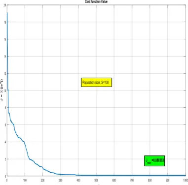
from rows 1 to 12 related to column y in the table. The method of changing the cost function by PSO algorithm is shown in Figure 6.
As shown in Figure 6, after 1000 sages of generation production, optimization with PSO algorithm has reached the value of the cost function jmin = 0.0883.
Weight variations in the optimization process are shown in Figure 7.
As shown in Figure 7, weights have converged to constant values. The final values of these weights are placed in the neural network and the network is evaluated for both training data and experimental data. The changes in the neuron neuronal penetration radii in the optimization process are shown in Figure 8.
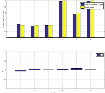
As shown in Figure 8, the penetration radii converge toconstant values. In Figure 9, the results of the detection of the rotor status, which is obtained by the neural network according to the training data, were compared with the main values. As seen, the neural network has detected the high accuracy of the rotor's state.
Figure 6. Variations in cost function (Total sum of absolute
faults on training data) by PSO optimization process
Figure 7. Variations in neural network weights in the
optimization process
It is worth noting that in addition to the training data, the neural network must also be correct for experimental data that falls within the training data range. In doing so, select a couple of experimental dataset are selected, the neural network obtained for them is tested, and the results were compared with the original results.
Figure 8. The changes in the neuron neuronal penetration radii in the optimization process
5. CONCLUSIONS
This paper examined an effective and precise method for determining the breakage fault of rotor bars of the induction motor in low load conditions. In order to improve the error detection process, Hilbert transform was used to extract the stator current signal. Neural network inputs are radial based function, 2sf harmonic position and its amplitude. Moreover, to improve and optimize the performance of the neural network, PSO
algorithm was used to find optimal network weights and neuron penetration radii. The results obtained show the exact and desirable performance of the proposed method in determining the number of broken rotors in the induction motor.
Figure 9. Neural network evaluation and its results compared
with the real results for the training data
Figure 10. Training data for testing the neural network
Figure 11. Results from the neural network versus Original
6. REFERENCES
1. Bazan, G.H., Scalassara, P.R., Endo, W., Goedtel, A., Godoy, W.F., and Palácios, R.H.C., “Stator fault analysis of three-phase induction motors using information measures and artificial neural networks”, Electric Power Systems Research, Vol. 143, No. 143, (2017), 347–356.
2. Ameid, T., Menacer, A., Talhaoui, H., and Harzelli, I., “Rotor resistance estimation using Extended Kalman filter and spectral analysis for rotor bar fault diagnosis of sensorless vector control induction motor”, Measurement, Vol. 111, (2017), 243–259. 3. Shi, P., Chen, Z., Vagapov, Y., and Zouaoui, Z., “A new
diagnosis of broken rotor bar fault extent in three phase squirrel cage induction motor”, Mechanical Systems and Signal Processing, Vol. 42, No. 1–2, (2014), 388–403.
4. Jerkan, D.G., Reljic, D.D., and Marcetic, D.P., “Broken Rotor Bar Fault Detection of IM Based on the Counter-Current Braking Method”, IEEE Transactions on Energy Conversion, Vol. 32, No. 4, (2017), 1356–1366.
5. Quiroz, J., Mariun, N., Mehrjou, M., Izadi, M., Misron, N., and Radzi, M.A.M., “Fault detection of broken rotor bar in LS-PMSM using random forests”, Measurement, Vol. 116, (2018), 273–280.
6. Abd-el-Malek, M., Abdelsalam, A.K., and Hassan, O.E., “Induction motor broken rotor bar fault location detection through envelope analysis of start-up current using Hilbert transform”, Mechanical Systems and Signal Processing, Vol. 93, No. 93, (2017), 332–350.
7. Rangel-Magdaleno, J., Peregrina-Barreto, H., Ramirez-Cortes, J., and Cruz-Vega, I., “Hilbert spectrum analysis of induction motors for the detection of incipient broken rotor bars”,
Measurement, Vol. 109, (2017), 247–255.
8. Xu, B., Sun, L., Xu, L., and Xu, G., “Improvement of the Hilbert Method via ESPRIT for Detecting Rotor Fault in Induction Motors at Low Slip”, IEEE Transactions on Energy Conversion, Vol. 28, No. 1, (2013), 225–233.
9. Konar, P., and Chattopadhyay, P., “Multi-class fault diagnosis of induction motor using Hilbert and Wavelet Transform”, Applied Soft Computing, Vol. 30, (2015), 341–352.
10. Chine, W., Mellit, A., Lughi, V., Malek, A., Sulligoi, G., and
Massi Pavan, A., “A novel fault diagnosis technique for photovoltaic systems based on artificial neural networks”,
Renewable Energy, Vol. 90, (2016), 501–512.
11. Sun, J., Shao, S.Y., and Yan, Q., “Induction motor fault diagnosis based on deep neural network of sparse auto-encoder”,
Journal of Mechanical Engineering, Vol. 52, No. 9, (2016), 65–71.
12. Bessam, B., Menacer, A., Boumehraz, M., and Cherif, H., “Detection of broken rotor bar faults in induction motor at low load using neural network”, ISA Transactions, Vol. 64, (2016), 241–246.
13. Jia, F., Lei, Y., Lin, J., Zhou, X., and Lu, N., “Deep neural networks: A promising tool for fault characteristic mining and intelligent diagnosis of rotating machinery with massive data”,
Mechanical Systems and Signal Processing, Vol. 72–73, (2016), 303–315.
14. Bachir, S., Tnani, S., Trigeassou, J.C., and Champenois, G., “Diagnosis by parameter estimation of stator and rotor faults occurring in induction machines”, IEEE Transactions on Industrial Electronics, Vol. 53, No. 3, (2006), 963–973. 15. Osman, S., and Wang, W., “A Morphological Hilbert-Huang
Transform Technique for Bearing Fault Detection”, IEEE Transactions on Instrumentation and Measurement, Vol. 65, No. 11, (2016), 2646–2656.
16. Eberhart, R., and Kennedy, J., “A new optimizer using particle swarm theory”, In MHS’95, Proceedings of the Sixth International Symposium on Micro Machine and Human Science, IEEE, (1995), 39–43.
17. Tarafdar Hagh, M., and Ghadimi, N., “Radial Basis Neural Network Based Islanding Detection in Distributed Generation”,
International Journal of Engineering - Transactions A: Basics, Vol. 27, No. 7, (2014), 1061–1070.
18. Strumiłło, P., and Kamiński, W., “Radial Basis Function Neural Networks: Theory and Applications”, Physica-Verlag HD, Heidelberg, (2003), 107–119.
19. Mousavi, Y., and Alfi, A., “A memetic algorithm applied to trajectory control by tuning of Fractional Order Proportional-Integral-Derivative controllers”, Applied Soft Computing, Vol. 36, No. 36, (2015), 599–617.
Optimal Rotor Fault Detection in Induction Motor Using Particle-Swarm
Optimization Optimized Neural Network
T. Yektaniroumand, M. Niaz Azari, M. Gholami
Department of Electrical Engineering, University of Science and Technology of Mazandaran, Behshahr, Iran
P A P E R I N F O
Paper history:
Received 12 May 2018
Received in revised form 23 June 2018 Accepted 26 October 2018
Keywords: Fault Detection Induction Motor Hilbert Transform Neural Network Particle-Swarm Optimization کچ ی هد رد نیا پ ر و ژ ه هبش هئارا و یسررب کی شور تهجرثؤم ییاسانش یگتسکش هلیم یاه اناسر رد میس ر یچیپ و ییاقلا روتوم روت
هکبش زا هدافتسا اب مک راب طیارش رد رد .تسا هدش هتخادرپ یعاعش هیاپ عباوت یبصع یاه
نیا تسدب تهج یداهنشیپ شور
ندروآ یدورو ناونعب روتاتسا شوپ لانگیس هنماد و سناکرف زا .تسا هدش هدافتسا تربلیه زا روتاتسا نایرج لانگیس شوپ
ر یاطخ تیعضو هکبش یجورخ و هدش هدافتسا یبصع هکبش و
هلیم دادعت ،روت ه
،یگتسکش یاطخ یاراد یاناسر یا
یم هنیهب متیروگلا زا نینچمه .دشاب نییعت تهج تارذ هوبنا یزاس
نزو هنیهب یبصع هکبش رد نورن ذوفن عاعش و هکبش یاه
ناشن یداهنشیپ شور زا هدمآ تسدب جیاتن .تسا هدش هدافتسا صیخشت تهج رد شور دمآراک و بولطم درکلمع هدنهد
هلیم یگتسکش یاطخ ر رد اناسر یاه
و یم مک راب طیارش رد ییاقلا روتوم روت دشاب
.
![Figure 1. The model of induction motor with faulty rotor [14]](https://thumb-us.123doks.com/thumbv2/123dok_us/24216.2002659/2.595.337.514.102.196/figure-model-induction-motor-faulty-rotor.webp)
![Figure 3. RBFN neural network with 12 neurons in the hidden layer to detect the rotor status [17, 18]](https://thumb-us.123doks.com/thumbv2/123dok_us/24216.2002659/4.595.87.253.99.283/figure-rbfn-neural-network-neurons-hidden-detect-status.webp)