Iranian Journal of Electrical and Electronic Engineering, Vol. 15, No. 3, September 2019 352
A New DPC-SVM for Matrix Converter Used in Wind Energy
Conversion System Based on Multiphase Permanent Magnet
Synchronous Generator
E. Bounadja*(C.A.), Z. Boudjema* and A. Djahbar*
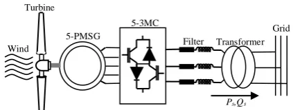
Abstract: This paper proposes a novel wind energy conversion system based on a Five-phase Permanent Magnetic Synchronous Generator (5-PMSG) and a Five to three Matrix Converter (5-3MC). The low cost and volume and also eliminating grid side converter controller are attractive aspects of the proposed topology compared to the conventional with back-to-back converters. The control of active and reactive power injected to the grid from the proposed system is carried out by a Direct Power Control (DPC) combined with a Space Vector Modulation (SVM). An advantage of this control, compared with the Conventional Direct Power Control (C-DPC) method, is that it eliminates the lookup table and lowers grid powers and currents harmonics through the use of a standard PI controller instead of hysteresis comparators. The efficiency of proposed whole system has been simulated by using MATLAB/Simulink environment.
Keywords: Five-Phase Permanent Magnetic Synchronous Generator (5-PMSG), Five to Three-Phase Matrix Converter (5-3MC), Grid Active and Reactive Powers, Direct Power Control (DPC), Space Vector Modulation (SVM), Wind Turbine.
1 Introduction1
OWADAYS the wind turbine conversion systems using the direct-driven three-phase Permanent Magnet Synchronous Generator (PMSG) are suitable and promising for application in wind farms [1-4]. The PMSG can be constructed with a large number of poles and can be operated as low speed direct-driven system without gearbox. This results in reduction of installation and maintenance costs and provides an advantage over the other types of generators. Furthermore, it has many advantages over induction generator, including: higher reliability, higher power, higher efficiency, higher torque, and simple control methods [3, 4]. On the other hand, multiphase PMSG shows other advantages over PMSG, such as reducing the amplitude and increasing the frequency of torque pulsations and higher
Iranian Journal of Electrical and Electronic Engineering, 2019. Paper first received 26 July 2018 and accepted 18 February 2019. * The authors are with the Department of Electrical Engineering, University of Hassiba Benbouali, Chlef, Algeria.
E-mails: [email protected], [email protected] and
Corresponding Author: E. Bounadja.
reliability [5-7]. Therefore, multiphase PMSG is very attractive for application of renewable energy [8]. Several works on five phase PMSG based wind turbine with back-to-back converters have been studied recently as in [5-7]. However, the cost, volume and the number of power electronic converters increase the
complexity of this topology. Due to these
disadvantages, the MC can be used as an alternative to DC-link voltage-sourced converter for wind energy conversion systems. In addition, the main advantages of the MC are the ability to generate sinusoidal input-output voltage and current and the possibility of adjusting input power factor [8-14]. On the other hand, MC application has been adapted for specific objectives and has not been generalized for wind power conversion systems based on multiphase PMSG generators as in [10-14, 17, 18].
A review of the existing literature, the author in [8] proposed a wind energy conversion systems based on MC. The system studied by this author is based on a six-phase asymmetrical squirrel cage induction generator (SCIG) and MC as power electronic interface between six-phase SCIG and electrical network. However, the power control injected to the grid from this system has
N
Iranian Journal of Electrical and Electronic Engineering, Vol. 15, No. 3, September 2019 353
not been investigated. In this purpose, our article focuses on this issue and investigates the control of 5-phase PMSG in wind energy conversion system based on MC.
Most of studies for the control of PMSG based wind turbine have focused recently. For example, [3] proposed an improvement vector control algorithms for the machine side converter and for the grid side converter. The control of active and reactive power has been applied with the application of voltage oriented control. However, this strategy requires rotary coordinate transformation and depends on the system parameters.
One of most and recent methods in controlling wind
powers is the Conventional Direct Power
Control (C-DPC). This method is characterized by its fast dynamic response, simple structure and robust response against parameter variation. In C-DPC strategy, active and reactive powers are estimated, using
current measurements, controlled directly with
hysteresis comparators and using a switching table similar to the one used in direct torque control (DTC) applied for AC machines as presented in [15,16]. The use of the DPC method in wind energy conversion systems based on PMSG has been the subject of a few studies. Study [4] proposed a PMSG connected to the grid via back to back converter. In this paper, the control of machine side converter is achieved by a conventional DTC and the grid side converter is controlled by a DPC. However, the most significant drawback of the this strategy is the variable switching frequency which mainly depends on the sampling frequency, the switching table structure, hysteresis bands, and the converter switching status. This variable switching frequency will produce a broadband harmonic spectrum in the AC line currents. For this reason, the design of filters in the AC line will be difficult and expensive [17, 19]. To surmount this inconvenience, we replace hysteresis comparators and swishing table existing in C-DPC by PI regulators with SVM resulting in a constant switching frequency of the power converter.
There are no researches in literature, to the best of our knowledge, of the use of DPC-SVM for the 5-phase PMSG based wind turbine using a 5-3MC. In this context, the present study was an attempt to combine the DPC approach with SVM for 5-phase PMSG connected to the grid via 3MC. This combination enables 5-phase PMSG based wind turbine to obtain the unit input power factor and lowers the grid powers and current harmonics. Therefore, it improves the control performance of the system. In addition, the propounded approach eliminates the lookup table and the nonlinearity effect of the hysteresis blocks through the use of the PI controller. Finally, a comparison of whole system performances, obtained by the proposed DTC-SVM and those determined by the C-DPC, is presented and validated by simulation in Matlab/Simulink.
2 General System Description
As shown in Fig.1, the system analysed is a variable speed wind turbine based on a 5-PMSG and 5-3MC connected to the grid via RL filter. Due to the low generator speed, the rotor shaft is coupled directly to the generator, which means that no gearbox is needed.
2.1 Wind Turbine Aerodynamic Model
The mechanical power produced by wind turbine can be expressed as below:
31 2
m P w
P ρAC λ,β v (1)
where: ρ is air density, A = πR2 is area swept by the
rotor blades, R is turbine blade radius, Cp is wind
turbine power coefficient, β is blade pitch angle, vw is
wind speed, λ is tip speed ratio, which is defined as:
m w
R v
(2)where Ωm is angular speed of turbine rotor.
The mechanical equation of wind turbine system is given by:
m m em f m
d
T T K J
dt
(3)
where Tmis the mechanical torque of wind turbine, Tem
is the electromagnetic torque of generator, J is the total
inertia of the system, Kf is the coefficient of viscous
friction.
The power coefficient Cp can be approximated, as
relationship of tip speed ratio λ and blade pitch angle β,
by the following expression [4]:
1 2 3 3 4
5 3 6
1 0.035 ( , )
0.08 1
1 0.035 exp
0.08 1
p
C C C C C
C C
(4)
where C1 = 0.5176, C2 = 116, C3 = 0.4, C4 = 5, C5 = 21,
C6 = 0.0068.
2.2 Modelling of 5-PMSG
The stator voltage equations of the 5-PMSG in the
Fig. 1 Diagram of the grid connected 5-PMSG based on 5-3MC.
Wind
5-3MC Turbine
Grid 5-PMSG
Filter Transformer
Ps,Qs
Iranian Journal of Electrical and Electronic Engineering, Vol. 15, No. 3, September 2019 354
synchronous rotating dq reference frame can be
described as follows [5-7]:
d d d m q
q q q m d
d v Ri dt d v Ri dt (5)
The components of stator flux vector in this reference frame can be given by:
d d q q f
Li Li (6)
The additional stator equations, which describe the
generator in the (xy) plane, are:
x x x y y y d v Ri dt d v Ri dt (7) x x y y Li Li (8)
The electromagnetic torque of 5-PMSG can be expressed by the following equation:
5 2
em f q
T p i (9)
2.3 Five to three-phase MC
The topology of the 5-3MC discussed in this paper is shown in Fig. 2. Its configuration is fictitiously divided
Fig. 2 The simplified topology of 5-3MC.
into a rectifier input stage and an inverter output stage, which are directly connected on the DC side. In inverter output stage, SVM method is applied for output voltage space vectors. Then the AC-AC converter is derived by eliminating the fictitious DC link.
The switching function of each electronic power switch of the considering 5-3MC is defined as follows:
mn mn , , , , ,1 if S closed
0 if S open , ,
mn
m A B C D E S
n a b c
(10)
The input phase should never be short-circuited; therefore, only one switch can be in on-state in each leg at any instant:
1,
An Bn Cn Dn En
S S S S S n a,b,c (11)
The proposed 5-3MC output phase voltages are made up of from its input phase voltages as below:
A a Aa Ba Ca Da Ea B b Ab Bb Cb Db Eb C Ac Bc Cc Dc Ec D c
E
V
V S S S S S V
V S S S S S V
S S S S S V
V V (12)
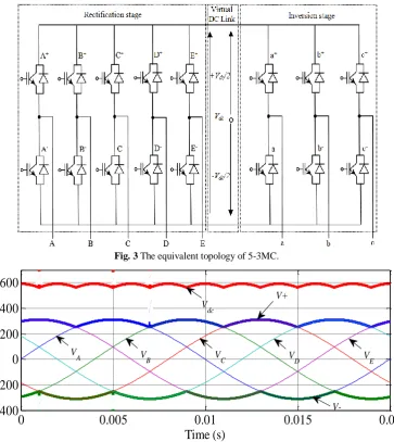
2.3.1 Five-Phase Rectifier Input Stage
According to Fig.3, the virtual intermediate voltage
Vdccan be deduced as below:
dc
V VV (13)
The virtual potentials V+ and V- will be varying as
function of the five-phase inputs and the rectification control functions as follows:
A B C D E V V
V A B C D D
V
A B C D E
V V V (14)
where m+ and m- (m= {A, B, C, D, E}) are the
rectification control functions, defined by:
1 if is the most postive input phase 0 if not
1 if is the most negative input phase 0 if not
m m V m V m (15)
The virtual intermediate voltage Vdc are illustrated in
Fig. 4.
Iranian Journal of Electrical and Electronic Engineering, Vol. 15, No. 3, September 2019 355
Fig. 3 The equivalent topology of 5-3MC.
0
0.005
0.01
0.015
0.02
-400
-200
0
200
400
600
Time (s)
V
D VE
V+ V
dc
V
A VB VC
V-Fig. 4 Input voltages and virtual potentials.
2.3.2 Three-Phase Inverter Output Stage
A Inverter Output Voltages
The link between the virtual middle potential and the output voltages of 5-3MC (Fig. 3) is given as follows:
ao bo co
V a a
V
V b b
V
c c
V
(16)
where n+ and n- (n= {a, b, c}) are the modulation
functions (binary signals) similar to that used in conventional SVM control of standard inverter. It will be synthesizes in the following section.
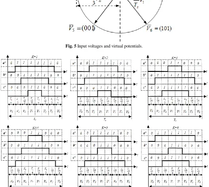
B SVM of Three-Phase Inverter Output Stage
Six power switches have eight possible switching
combinations in the Three-phaseDC-AC converter. So
there are 8 voltage space vectors defined by these 8 switching combinations, which consist of a circle
including six effective space vectors and two zero ones. The circle is divided into 6 equal sectors. The demanded
output voltage space vector Vs located in a sector can be
synthesized by the adjacent two effective vectors and one zero vector consisting of this sector according to SVM method [19]. The basic output voltage space vectors and the corresponding switching states are represented in Fig. 5.
Suppose Vs locates in the sector k which is made up of
two adjacent effective vectors Vk , Vk+1 and a zero one Vz (Z=0, 7), and Vs leads α-axis by ϕ , then Vs can be
composed of Vk , Vk+1 and Vz , as below:
1 0
1
k k
s k k z
s s s
T T T
V V V V
T T T
(17)
with
1
0 1
3 3 ( 1)
sin( ), sin( ),
3 3
s s s s
k k
dc dc
s k k
T V k T V k
T T
V V
T T T T
(18)
Iranian Journal of Electrical and Electronic Engineering, Vol. 15, No. 3, September 2019 356
Fig. 5 Input voltages and virtual potentials.
Fig. 6 Input voltages and virtual potentials.
where Tsis the switching period and Tk, Tk+1, T0 are the
switching-on time of voltage vectors Vk, Vk+1 and Vz
respectively.
The modulation functions n+ (n= {a, b, c}) are
obtained as represented in Fig. 6.
The modulation functions n- (n= {a, b, c}) can
similarly be obtained as fellow:
1
n n (19)
2.3.3 Five to Three MC Switching Functions
The above-mentioned DC-link is imaginary that is say
the rectifying and inverting of 5-3MC are conducted at the same time. Therefore this DC-link should be eliminated by substitution of (14) in (16), so, the output-line voltages are obtained as follows:
A
ao B
bo C
D co
E
V
V a a V
A B C D D
V b b V
A B C D E
c c V
V
V
(20)
Iranian Journal of Electrical and Electronic Engineering, Vol. 15, No. 3, September 2019 357
Equation (20) can be written as follow:
A ao Aa Ba CA Da Ea B bo Ab Bb Cb Db Eb C Ac Bc Cc Dc Ec D co E V V V V V V V V (21)
where τmn represent the reference signals defined as
follows:
, ,
mn m n m n m A,B,C,D,D,E
n a,b,c
(22)
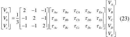
Based on (21) and on the conventional mathematical model of an inverter, the 5-3MC output voltages are expressed as below:
2 1 1
1
1 2 1
3
1 1 2
A
a Aa Ba CA Da Ea B
b Ab Bb Cb Db Eb C
Ac Bc Cc Dc Ec D
c E V V V V V V V V (23)
The similarly between (12) and (23), can deduce the 5-3MC switching functions as follows:
1
(2 )
3 1
(2 ) , 3
1
(2 )
3
ma ma mb mc
mb mb ma mc
mc mc ma mb
S S S m A,B,C,D,E (24)
3 DPC-SVM of Grid Connected 5-PMSG
3.1 Control Scheme of DPC-SVM
The dynamic model of grid side electrical circuits is presented as [6]:
gd
gd g gd g g g gq cgd gq
gq g gq g g g gd cgq
di
v R i L L i v
dt di
v R i L L i v
dt (25)
where vgd and vgq are the dq components of the grid
voltage vector, igd and igqare the dq components of the
grid current vector; vgcd and vgcqare the dq components
of the voltage vector of grid side converter, Lg and Rg
are inductance and resistance of the grid filter, ωg is
angular frequency of the grid voltage.
In conventional DPC (C-DPC), the hysteresis controllers and switching table have been used. This control strategy is characterized by varied switching
frequency of control signals. In the control system of 5-3MC considered in this paper, a DPC-SVM method has been applied. The block scheme of control system is presented in Fig. 7. This method has simple structure, low number of coordinates transformations and good
dynamic properties. The temporary angle positions θgof
the grid voltage vector are obtained from the Phase Locked Loop (PLL) block. The applied PLL system is a feedback system with PI-regulator tracking the phase angle of grid voltage vector [6].
The control algorithm of DPC-SVM is based on the active and reactive power estimator as [14]:
3 ( ) 2 3 ( ) 2
g gd gd gq gq
g gq gd gd gq
p V i V i
Q V i V i
(26)
The control strategy of DPC-SVM for 5-3MC uses two control loops with PI controllers. These inner control loops regulate the active and reactive power of AC grid. The estimated values of active and reactive grid power are compared with the reference values. In the typical control systems, the reactive grid power reference is set to zero in order to perform the operation at unity power factor. The output signals from PI
controllers determine the reference voltages vgcα_refand
vgcβ_ref for SVM of 5-3MC.
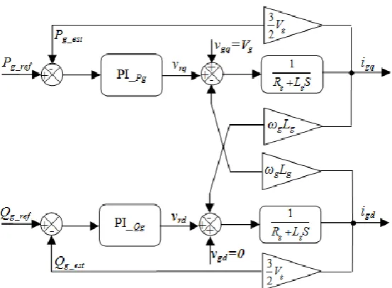
3.2 Synthesis of Grid Active and Reactive Power Controllers
To ensure a pure active power exchange from the wind generator and maintain the reactive power exchange to the grid, which guarantees a desirable power factor during the generator function, an
orientation of d-axis of the synchronous reference frame
with grid voltage vector is required [20, 21]. So (26) becomes as follows:
0 gd g gq v v V (27)
The grid active and reactive power in (dq) coordinates
has the form after orientation as below:
3 2 3 2
g g gq
g g gd
p V i
Q V i
(28)
Based on the above equations, the schematic diagram of power control loops take the form as illustrated in Fig. 8.
4 Simulation Results
The simulation model of wind energy conversion
Iranian Journal of Electrical and Electronic Engineering, Vol. 15, No. 3, September 2019 358
Fig. 7 Control diagram of DPC-SVM of the whole system.
Fig. 8 Synthesis of grid active and reactive power controllers.
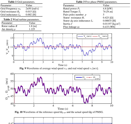
system with the considered control systems has been implemented in MATLAB/Simulink. The aim of simulation was the investigation of properties of control systems. The used wind turbine parameters are presented in Tables 1-3.
The obtained simulation results of considered wind energy conversion system are presented in Figs. 9-22. The considered control of whole system has been
tested for the wind speed vw during the period of the
10s, while, the average wind speed vwa has been adopted
as equal to 11m/s as presented in Fig. 9.
Fig. 10 shows the waveforms of optimal Ωg-opt and
measured angular speed Ωg of 5-PMSG obtained from
simulation of control system. It can be seen, that the
generator speed Ωg is accurately adjusted to the
waveforms of optimal speed Ωg-opt, which is obtained
from MPPT algorithm.
The obtained waveforms of power coefficient Cp and
tip speed ratio λ at various wind speeds have been
presented in Figs. 11-12.
Fig. 13 presents the responses of electromagnetic
torque Tem of 5-PMSG and mechanical torque Tm of
Iranian Journal of Electrical and Electronic Engineering, Vol. 15, No. 3, September 2019 359
Table 1 Grid parameters.
Parameter Value
Grid Frequency ωg 2π50 [rad/s] Grid resistance Rg 0.015 [Ω] Grid inductance Lg 0.002 [H]
Table 2 Wind turbine parameters.
Parameter Value
Rotor radius R 1.8 [m] Air density ρ 1.225
Table 3 Five phase PMSG parameters.
Parameter Value
Rated power Pn 4.8 [kW]
Rated Torque Tn 76 [N.m]
Pairs poles number p 5 Stator resistance Rs 0.425 [Ω] Stator dq-axis inductance Ls 0.00835 [H]
Inertia J 0.01197 [kg.m2]
Flux linkage ψf 0.433 [Wb]
0 1 2 3 4 5 6 7 8 9 10
9 11 13
Time (s)
V w
,V
w
a
(m
/s
)
Vw (m/s) Vwa (m/s)
Fig. 9 Waveforms of average wind speed vwa and real wind speed vw [m/s].
0 2 4 6 8 10
40 45 50 55 60
Time (s)
, g
g-o
pt
(m
/s
) g g-op t
Fig. 10 Waveforms of the reference speed Ωg-opt and the actual speed Ωg of PMSG.
0 1 2 3 4 5 6 7 8 9 10
0 0,2 0,47
Time (s)
C p
Fig. 11 Waveform of power coefficient of wind turbine Cp.
0 1 2 3 4 5 6 7 8 9 10
0 2 4 6 8 10
Time (s)
Fig. 12 Waveforms of tip speed ratio λ.
Iranian Journal of Electrical and Electronic Engineering, Vol. 15, No. 3, September 2019 360
wind turbine during the considered variation of wind speed. The considered control system allows fast
responses of the electromagnetic torque Temof 5-PMSG
during temporary time variations of the wind speed.
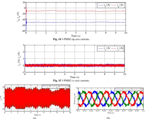
Figs. 14-15 show the waveforms of machine dq-axis
and xy-axis currents. The response of current vector
components (id, iq) is practically changing according to
variations of wind speed. However, the components (ix, iy) have been kept at zero value, as desired.
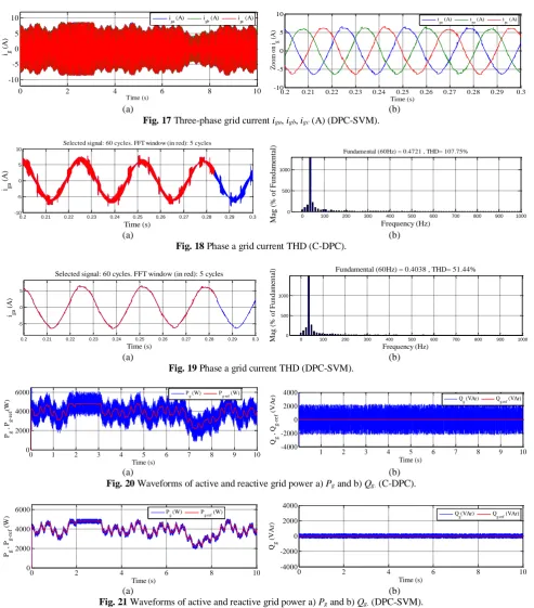
Figs. 16-17 display the three-phase current waveforms
injected to the grid by the conversion system controlled by both C-DPC and DPC-SVM. It can be seen, that this current has a sinusoidal form and changing according to the variations of wind speed for both methods. The effectiveness of proposed strategy is shown in these figures. Also, Figs. 18-19 show the improvement of stator currents THD where it clear to see that by using the SVM strategy the current THD decreases justifying the use of the proposed control, (THD of 107.75 % for the C-DPC and 51.44% for the proposed DPC-SVM).
0 1 2 3 4 5 6 7 8 9 10
-400 -200 0 200 400
Time (s)
T m
, T
e
m
(N
.m
) Tm (N.m) Tem (N.m)
Fig. 13 Waveforms of electromagnetic torque Tem of 5-PMSG and mechanical torque Tm of wind turbine.
0 1 2 3 4 5 6 7 8 9 10
-80 -60 -40 -20 0 20
Time (s)
i d
, i q
(A
)
i
d (A) iq (A)
Fig. 14 5-PMSG dq-axis currents.
0 1 2 3 4 5 6 7 8 9 10
-1 0 1 2 3
Time (s)
i x
(A
),
i y
(A
)
i
x (A) iy (A)
Fig. 15 5-PMSG xy-axis currents.
0 1 2 3 4 5 6 7 8 9 10
-10 -5 0 5 10
Time (s)
ig
(A
)
iga (A) igb (A) igc (A)
0.2 0.21 0.22 0.23 0.24 0.25 0.26 0.27 0.28 0.29 0.3 -10
-5 0 5 10
Time (s)
Z
o
o
m
o
n
ig
(A
)
i
ga (A) igb (A) igc (A)
(a) (b)
Fig. 16 Three-phase grid current iga, igb, igc (A) (C-DPC).
Iranian Journal of Electrical and Electronic Engineering, Vol. 15, No. 3, September 2019 361
0 2 4 6 8 10
-10 -5 0 5 10 Time (s) ig (A )
iga (A) igb (A) igc (A)
0.2 0.21 0.22 0.23 0.24 0.25 0.26 0.27 0.28 0.29 0.3 -10 -5 0 5 10 Time (s) Z o o m o n ig (A ) i
ga (A) iga (A) igc (A)
(a) (b)
Fig. 17 Three-phase grid current iga, igb, igc (A) (DPC-SVM).
0.2 0.21 0.22 0.23 0.24 0.25 0.26 0.27 0.28 0.29 0.3
-10 -5 0 5 10
Selected signal: 60 cycles. FFT window (in red): 5 cycles
Time (s)
iga
(A
)
0 100 200 300 400 500 600 700 800 900 1000
0 500 1000
Frequency (Hz)
Fundamental (60Hz) = 0.4721 , THD= 107.75%
M ag (% o f F u n d am en ta l)
0.2 0.21 0.22 0.23 0.24 0.25 0.26 0.27 0.28 0.29 0.3
-10 -5 0 5 10
Selected signal: 60 cycles. FFT window (in red): 5 cycles
Time (s)
iga
(A
)
0 100 200 300 400 500 600 700 800 900 1000
0 500 1000
Frequency (Hz)
Fundamental (60Hz) = 0.4721 , THD= 107.75%
M ag (% o f F u n d am en ta l)
(a) (b)
Fig. 18 Phase a grid current THD (C-DPC).
0.2 0.21 0.22 0.23 0.24 0.25 0.26 0.27 0.28 0.29 0.3
-5 0 5
Selected signal: 60 cycles. FFT window (in red): 5 cycles
Time (s)
iga
(A
)
0 100 200 300 400 500 600 700 800 900 1000
0 500 1000
Frequency (Hz)
Fundamental (60Hz) = 0.4038 , THD= 51.44%
M ag (% o f F u n d am en ta l)
0.2 0.21 0.22 0.23 0.24 0.25 0.26 0.27 0.28 0.29 0.3
-5 0 5
Selected signal: 60 cycles. FFT window (in red): 5 cycles
Time (s) iga
(A
)
0 100 200 300 400 500 600 700 800 900 1000
0 500 1000
Frequency (Hz)
Fundamental (60Hz) = 0.4038 , THD= 51.44%
M ag (% o f F u n d am en ta l)
(a) (b)
Fig. 19 Phase a grid current THD (DPC-SVM).
1
0 2 3 4 5 6 7 8 9 10
0 2000 4000 6000 Time (s) Pg , P g -r e f (W )
Pg (W) Pg-ref (W)
1 2 3 4 5 6 7 8 9 10
-4000 -2000 0 2000 4000 Time (s) Qg , Q g -r e f (V A r) Q
g (VAr) Qg-ref (VAr)
(a) (b)
Fig. 20 Waveforms of active and reactive grid power a) Pg and b) Qg. (C-DPC).
0 2 4 6 8 10
0 2000 4000 6000 Time (s) Pg , P g -r e f (W
) Pg (W) Pg-ref (W)
0 2 4 6 8 10
-4000 -2000 0 2000 4000 Time (s) Qg (V A r)
Qg(VAr) Qg-ref (VAr)
(a) (b)
Fig. 21 Waveforms of active and reactive grid power a) Pg and b) Qg. (DPC-SVM).
In Fig. 20 the active and reactive powers injected to the grid, controlled via the proposed DPC-SVM, are displayed, while, in a comparative way, Fig. 21, describes these quantities under the conventional direct power control (C-DPC). One can conclude that, under the proposed control algorithm, the grid power amounts track their references values with smooth profiles, with ripple-free. Also, from these figures, it can be noticed, that only the active power generated by the proposed
system is fully delivered to the AC grid, while the reactive power is equal to zero.
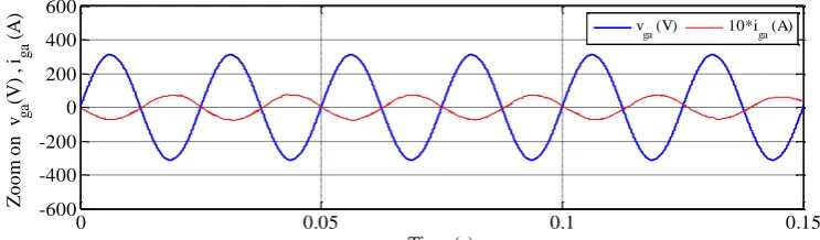
Finally, Fig. 22 shows the waveform of the grid voltage and current delivered by the generating system, between 0 s and 0.15 s. It can be seen that the voltage is in phase opposition with the current, which proves that the 5-PMSG, drives with unitary factor power, as can be checked on Fig. 21.
Iranian Journal of Electrical and Electronic Engineering, Vol. 15, No. 3, September 2019 362
0 0.05 0.1 0.15
-600 -400 -200 0 200 400 600
Time (s)
Z
o
o
m
o
n
v ga
(V
)
,
i ga
(A
)
v
ga (V) 10*iga (A)
Fig. 22 Waveforms of grid phase voltage vga and current iga (DPC-SVM).
5 Conclusion
In this paper, a new scheme for grid connected 5-PMSG has been presented. The conventional back-to-back converter has been replaced by a 5-3MC. In the proposed scheme, bulky DC-link capacitors and also the grid side converter has been eliminated. In this study, a simple way to control the 5-3MC by considering a virtual DC link between two conversions stage (rectification and inversion) is used. In order to control the active and reactive power injected to the grid a DPC with SVM have been explored. This method eliminates the lookup table and reduces the grid powers and currents harmonics by replacing hysteresis comparators with PI controllers. Another advantage of the propounded approach is that it achieves the unit input power factor. A simulation of the considered control algorithms, with a suitable wind variation, has been applied to whole system. Simulation results show good performances. Therefore, the control method objectives are achieved.
References
[1] J. C. Hui, A. Bakhshai, and P. K. Jain, “An energy
management scheme with power limit capability and an adaptive maximum power point tracking for small standalone PMSG wind energy systems,”
IEEE Transactions on Power Electronics, Vol. 31,
No. 7,pp. 4861–4875, 2016.
[2] C. Wei, Z. Zhang, W. Qiao, and L. Qu, “An
adaptive network-based reinforcement learning method for MPPT control of PMSG wind energy
conversion systems,” IEEE Transactions on Power
Electronics, Vol. 31, No. 11, pp. 7837–7848, 2016.
[3] P. Gajewski and K. Pieńkowski, “Advanced control
of direct-driven PMSG generator in wind turbine
system,” Archives of Electrical Engineering,
Vol. 65, No.4, pp. 643–656, 2016.
[4] P. Gajewski and K. Pieńkowski, “Direct torque
control and direct power control of wind turbine
system with PMSG,” Przegląd Elektrotechniczny,
Vol. 92, No. 10, pp. 249–253, 2016.
[5] A. Youssef, A. Mahmoud, M. Sayed,
N. Abdel-Wahab, and G. S. Salman, “MPPT control technique for direct-drive five-phase PMSG wind
turbines with wind speed estimation,” International
Journal of Sustainable and Green Energy, Vol. 4, No. 5, pp. 195–205, 2015.
[6] S. Rhaili, A. Abbou, S. Marhraoui, and
N. El Hichami, “Vector control of five-phase permanent magnet synchronous generator based
variable-speed wind turbine,” in International
Conference on Wireless Technologies, Embedded and Intelligent Systems (WITS), Fez, Morocco, 2017.
[7] H. H. Mousa, A. R. Youssef, and E. M. Mohamed,
“Model predictive speed control of five-phase PMSG based variable speed wind generation
system,” in Twentieth International Middle East
Power Systems Conference (MEPCON), Cairo, Egypt, 2018.
[8] A. Djahbar, A. Zegaoui, and M. Aillerie,
“Multiphase wind energy conversion systems based
on matrix converter,” Automatika, Vol. 57, No. 2,
pp. 396–404, 2016.
[9] A. Badiee-Azandehi, A. Yousefi-Talouki, and
M. Rezanejad, “Direct torque control space vector modulation of five-phase interior permanent magnet synchronous motor using matrix converter,”
Australian Journal of Electrical & Electronics Engineering, Vol. 12, No. 2, pp. 113–124, 2015.
[10]M. M. Rezaoui, L. Nezli, and M. O Mahmoudi,
“High performances of five–phase induction machine feeding by a [3×5] Matrix Converter”,
Journal of Electrical Engineering, Vol. 65, No. 2, pp. 83–89, 2014.
[11]M. M. Rezaoui, L. Nezli, M. O. Mahmoudi,
A. Kouzou, and H. Abu Rub, “A modified PWM three intervals control for a matrix converter in real
time,” Archives of Control Sciences, Vol. 3, No. 1,
pp. 85–98, 2014.
Iranian Journal of Electrical and Electronic Engineering, Vol. 15, No. 3, September 2019 363
[12]K. You, D. Xiao, M. F. Rahman, and M. N. Uddin,
“Applying reduced general direct space vector modulation approach of AC-AC matrix converter theory to achieve direct power factor controlled
three-phase AC-DC matrix rectifier,” IEEE
Transactions on Industry Applications, Vol. 50, pp. 2243–2257, 2014.
[13]H. Nikkhajoei, A. Tabesh, and R. Iravani,
“Dynamic model of a matrix converter for controller
design and system studies,” IEEE Transactions on
Power Delivery, Vol. 21, pp. 744–754, 2006.
[14]C. Klumpner, F. Blaabjerg, I. Boldea, and
P. Nielsen, “New modulation method for matrix
converters”, IEEE Transactions on Industry
Applications, Vol. 42, pp. 797–806, 2006.
[15]L. Xu and P. Cartwright, “Direct active and reactive
power control of DFIG for wind energy generation,”
IEEE Transactions on Energy Conversion, Vol. 21, No. 3, pp. 750–758, 2006.
[16]R. Datta and V. T Ranganathan, “Direct power
control of grid-connected wound rotor induction
machine without rotor position sensors,” IEEE
Transactions on Power Electronics, Vol. 16, No.3, pp. 390–399, 2001.
[17]M. Jafari, K. Abbaszadeh, and M. Mohammadian,
“A novel DTC-SVM approach for two parallel-connected induction motors fed by matrix
converter,” Turkish Journal of Electrical
Engineering & Computer Sciences, Vol. 26, pp. 1599–1611, 2018.
[18]T. D. Nguyen and H. H. Lee, “Development of a
three-to-five-phase indirect matrix converter with
carrier-based PWM based on space-vector
modulation analysis,” IEEE Transactions on
Industrial Electronics, Vol. 63, pp.13–24, 2016.
[19]T. Vajsz and L. Számel, “Improved modified
DTC-SVM methods for increasing the overload-capability of permanent magnet synchronous motor servo- and
robot drives–Part1,” Periodica Polytechnica
Electrical Engineering and Computer Science, Vol. 62, No. 3, pp. 65–73, 2018.
[20]B. K. O. Hasnaoui, M. Al Laqui, and J. Belhadj,
“PMSG gear-less wind turbine equipped with an
active and reactive power supervisory,”
International Journal of Renewable Energy Research, Vol. 4, No. 2, pp. 435–444, 2014.
[21]N. Freire, J. Estima, and A. Cardoso, “A
comparative analysis of PMSG drives based on vector control and direct control techniques for wind
turbine applications,” Przegląd Elektrotechniczny,
Vol. 88, No. 1, pp. 184–187, 2012.
E. Bounadja was born in Chlef, Algeria, in 1973. He received his Eng. and M.Sc. degrees in Electrical Engineering from the University of Hassiba Benbouali, Chlef, Algeria, in 1997 and 2008, respectively, and his Ph.D. degree in Electrical Engineering from the National Polytechnic School of Algiers, Algeria, in 2017. He is an Associate Professor at the Electrical Engineering Department of the University Hassiba Benbouali, Chlef, Algeria. His research activities include the power electronics, intelligent and robust controls in the wind-power systems.
Z. Boudjema was born in Chlef, Algeria, in 1983. He received his Eng. and M.Sc. degrees in Electrical Engineering from National Polytechnic School, Oran, Algeria, in 2006 and 2010, respectively, and his Ph.D. degree in Electrical Engineering from Djilali elyabes University, Sidi Belabès, Algeria, in 2015. He is an Associate Professor at the Electrical Engineering Department of the University Hassiba Benbouali, Chlef, Algeria. His research activities include application of robust control in the wind-solar power systems.
A. Djahbar was born in Chlef, Algeria, in February 1970. He received his Eng. and M.Sc. degrees in Electrical Engineering from the National Polytechnic School of Algiers, Algeria, in 1995 and 1998, respectively, and the Ph.D. degree in Electrical Engineering from the Mohamed Boudiaf University, Oran, Algeria, in 2008. He is a Full Professor at the Electrical Engineering Department of the University Hassiba Benbouali, Chlef, Algeria. His scientific work is related to multi machine drives, matrix converter and power quality.
© 2019 by the authors. Licensee IUST, Tehran, Iran. This article is an open access article distributed under the terms and conditions of the Creative Commons Attribution-NonCommercial 4.0 International (CC BY-NC 4.0) license (https://creativecommons.org/licenses/by-nc/4.0/).