Iranian Journal of Electrical & Electronic Engineering, Vol. 14, No. 3, September 2018 245
Active and Reactive Power Management of Wind Farm Based
on a Six Leg Tow Stage Matrix Converter Controlled by a
Predictive Direct Power Controller
S. Chikha*(C.A.)
Abstract: In this paper we propose a new configuration of the wind farm connecting with
an electrical grid. The proposed Wind Energy Conversion System (WECS) is based on a two stages six-leg matrix converter using to drive a two Doubly Fed Induction Machines operating at different wind speeds. Each Doubly Fed Induction Generator (DFIG) is controlled through the rotor currents using the Finite Set Model Predictive Model (FS-MBC). The proposed control method selects the optimal switching state of the converter that minimizes the cost function where it represents the desired behavior of the system. The optimal voltage vector is then applied to the output of the power converter. The most advantage of the proposed control is its simplicity in implementation, since the method avoids the use of any linear or nonlinear controllers except for the external speed loop and there is no need for any type of modulator such as in PWM or SVM modulation. A cost function is formulated according to desired performance such as regulation of the stator active and reactive powers of the DFIGs and reactive power in the filter side. The control algorithm selects and applies the optimal voltage vector to the DFIG rotor terminals. The supervision algorithm distributes the active and reactive power references in proportional way for each wind turbines. From a safety point, this algorithm provides each wind turbines still operate far from its limits. The performance of a six leg IMC in WECS chain is evaluated in term of a good tracking performance.
Keywords: Predictive Direct Power Control, Wind Farm, Doubly Fed Induction Generator,
Six Leg Tow Stage Matrix Converter, Cost Function.
1 Introduction1
ver the two last decades, wind energy conversion systems (WECS) have attracted more and more attention for maintaining the continuously growing energy needs of humanity. Wind energy systems using a doubly fed induction generator (DFIG) fed by a back to back converter is the most popular configuration due to the advantages of variable speed operation range and its four quadrants active and reactive power capabilities.
Iranian Journal of Electrical & Electronic Engineering, 2018. Paper first received 29 June 2016 and accepted 20 February 2018. * The author is with the Electrical Engineering and Automatic Laboratory LGEA, University of Larbi Ben M'hidi Oum El Bouaghi, 04000. Algeria.
E-mail: [email protected]. Corresponding Author: S. Chikha.
Due to Indirect matrix converter’s inherent advantages (such as no DC-link capacitor, the bi-directional power flow control (the capability of regeneration), the sinusoidal input-output waveforms and adjustable input power factor), also it can be employed to build a multi-drive system with multiple inverter stages (corresponding the usage!) [1-3].
The traditional wind turbines/wind farms directly connected to the distribution grid do not have such high control capabilities. These wind farms produce maximum possible power in normal operation and disconnect in the case of grid faults. They work autonomously without any centralized control. This situation has challenged the researchers to orient there researches to the algorithms of supervision of the wind farms and their connection with the network. Several techniques for the control and supervision of wind farms are currently emerging. Such as the control of the active
O
Iranian Journal of Electrical & Electronic Engineering, Vol. 14, No. 3, September 2018 246 and reactive power [4,5], voltage control [6,7],
frequency control [8] and the tolerance in relation to electrical grid faults.
The supervision algorithms are based on a proportional distribution of the active and reactive powers which are proposed in [9-11]. These algorithms are for purpose to distribute the production of the active and reactive power references for each wind turbines in proportional way, the algorithm taking a count a maximal reactive power capacity.
Among the two last decades, several control strategies for WECSs based DFIG have been reported in specialist literature starting from the basic idea that control does significantly improve all aspects of WECS and the most widely used techniques may be classified within the Field Oriented Control (FOC) techniques and the Direct Control techniques (DTC and DPC).
In FOC techniques, the rotor current is decomposed into direct component that controls the torque (the stator active power) and a quadrature component that commands the rotor flow (stator reactive power) and they are regulated separately with linear PI controllers. In [12-14], the block diagram of the power control of the DFIG incorporates a cascaded structure with four PI regulators, two PIs in the outer loops for stator active and reactive powers and two PIs in the inner rotor currents loops with also an additional PI loop for the speed. As a consequence, degradation in the dynamic performance is occurring due to time delays in the cascaded regulators and reduced robustness against model uncertainties. Simplified structures have been then proposed by eliminating sometimes inner current loops and sometimes the outer power loops but at least the control block contains for three PIs controllers. Direct Control techniques that are originated from Direct Torque Control DTC for induction machines in [11-13] and Direct Self Control DSC in [15] provide direct control of the machine’s torque reducing the complexity of the FOC control. These methods have been translated to control DFIG and are different from FOC in that they take into account the discrete nature of power converters and use a switching table to select the appropriate voltage vector to be applied on terminal machine. These techniques provide better transient torque control conditions rather than FOC without requiring neither current regulators nor coordinate transformations or any specific modulations like PWM or SVM for pulse generation since the PI regulators in FOC are eliminated and replaced by hysteresis comparators. However they still present some disadvantages compared to FOC such as the lack of direct current control, torque control difficulties at very low speeds and especially variable switching frequency behavior.
Since power converters have a discrete nature, FS-MPC appears as an attractive alternative that offers a completely different and powerful approach to control power converters. Several advantages of this control
method can be mentioned such as its fast-dynamic response; linear controllers in inner loops are not required, flexible method and good performance also the ability of implementation with standard commercial microprocessors. The method is based on the fact that a finite number of possible switching states can be generated by power converter. For the selection of the appropriate switching state to be applied to the system, a quality function must be defined and then evaluated for the predicted values on each sampling interval and the optimal switching state that minimizes the quality function is selected to be applied during the next sampling time [16,17].
The present paper aims to present a dispatching of the active and reactive power between the wind farm and an electrical grid. The active and reactive powers references are distributed by the supervisory proportional algorithm taking into count the reactive power capability. A predictive control method is used to control simultaneously the DFIG rotor powers and the reactive power of the filter side without the use of neither linear controllers nor inner loops. Simulation results are presented to confirm the effectiveness of the predictive control method and the supervisory proportional algorithm.
2 Modeling
2.1 Wind Turbine Characteristics
The turbine allows converting the aerodynamic energy into mechanical energy. The wind speed v applied to the blades of the turbine causes its rotation, and creates mechanical power on the shaft of the turbine, symbolized Pt given by [1]:
2 31
. , . . . .
2 i
ti p i i i i
P C B R V (1)
where, ρ is the air density (kg/m3), R is the blade radius
(in m), Cpis the performance coefficient of the turbine called also aerodynamic efficiency of the wind turbine which is a function of the pitch angle of rotor blades β (in degrees) and the tip-speed ratio λ , v is the wind speed in m/s.
The tip-speed ratio λ is given by: .
ti i i
i
R v
(2)
Ωt is the wind turbine speed (rad/s). The performance coefficient
,
i
p i i
C B has a theoretical limit, called the Betz limit, equal to 0.593 and which is never achieved in practice. In this work we used an approximate expression of the power coefficient as a function of the relative speed λi and the pitch angle of the blades βi [18]:
Iranian Journal of Electrical & Electronic Engineering, Vol. 14, No. 3, September 2018 247
, 0.35 0.00167 2
0.1 sin
14.34 0.3 0.1
0.0018 3 2
i
p i i i
i
i
i i
C
(3)
The coefficient of power of a wind turbine is a measurement of how efficiently the wind turbine converts the energy in the wind into electricity
Then the aerodynamic torque is given by:
3 2,
2 i
ti
ti p i i i i
ti i
P
C C B R V
(4)
The Cp (λ,β) characteristic (3) is illustrated in Fig. 1 where it shows the aerodynamic efficiency of the first turbine versus the tip speed ratio λ for different values of the pitch angle (β). In this figure, the characteristic of the power coefficient (Cp) in function of the tip speed ratio (λ) is varied with the variation in pitch angle (B).
At is clear, for each characteristics there is one point represent the maximal power corresponding optimal tip speed ration (λ opt).
2.2 DFIG Modeling
In order to obtain a decoupled active and reactive stator power control, we have chosen a two-phases reference frame dq linked to the rotating stator field. And by placing the stator flux vector (Ψs) on the d axis. Also on supposing, the stator resistance Rs negligible compared to the high stator reactance for the medium and high level power [19,20]:
1
1 dri
dri ri dri i s ri qri
ri
i
qri ri qri i s
qri
si ri
i s ri dri
di
v R i s w L i
dt L
M
v R i s v
di
L
dt L
s w L i
(5)
where (vdr, vqr) are rotor voltage components, (idr,iqr) are rotor current components, (Rr, Lr, Lm) are rotor resistance, rotor inductance and mutual inductance respectively.
σ = 1-M2/(L
sLr): The dispersion coefficient of the DFIG;
ws: The stator angular frequency (It is the same angular frequency of the grid).
si:The rotor slip.
i: This subscript is represent the number of the DFIG. The expressions of stator active and reactive powers are then given by:
. .
. .
. i
si s qri
si
s si s i
si dri
si si
M
P V i
L
V V M
Q i L L (6) 0 5 10 15 20 25 0 5 10 150 0.1 0.2 0.3 0.4
Pitch Angle [°] Tip speed ratio [Lambda]
Pow er C oef fic ien t (C p)
Fig. 1 3D plot of power coefficient Cp (λ,β).
2.3 Mathematical Model of a Two Stage Six Leg Matrix Converter
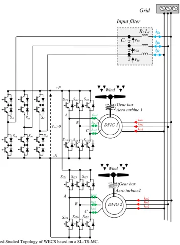
The WECS based on a DFIGs feeding bay a SL-TS-MC topology is shown in Fig. 2. It consists of a cascaded bidirectional controlled rectification stage and a tow voltage source inversion stages through a dc-link voltage without energy storage element.
The converter synthesizes a positive voltage in the dc-link by selecting a switching state in the rectifier that connects one phase to the point P and the other phase to the point N. In addition, the matrix converter includes a RLC filter in the input side which is needed to prevent over voltages and to provide filtering of the high frequency components of the input currents produced by the commutations and the inductive nature of the load [21]. The main advantages of this topology are: Reduces the system cost (reduce a number of legs
compared with a back to back three levels converters and no capacitance bank);
Reduces weight of the system;
Save space (the space of the capacitance bank for a medium and high power systems it is important). In the same time the SL-TS-MC save a same benefits to the indirect and direct matrix converter, as shown in following point [21]:
Adjustable input displacement factor, irrespective of the load;
The capability of regeneration (Four-quadrant operation);
High quality input and output waveforms;
The lack of bulky and limited lifetime energy storage components, such as electrolytic capacitors. The Table 1 shows a comparison between the proposed topology, back-to-back three-level converter and an indirect matrix converter. In order to control a two DFIGs we must using a two converters Back to back three levels or indirect matrix converter (so the number of the switches is multiplied by 2. Also, the number of the Dc-link in case of B2B-3L converter is product with 2). But with a six leg tow stage matrix converter no Dc-link banks and the number of the semi-conductor is reduced (so the global cost of the system is
Iranian Journal of Electrical & Electronic Engineering, Vol. 14, No. 3, September 2018 248
Grid
Rf,Lf
via
vib
vic
Cf
Input filter
ifa
ifb
ifc
Wind
Si24 Si26 Si22 icr1
iar1
ibr 1
DFIG 1
Aero turbine 1
ias1
ics1 ibs1
Gearbox
Si23 Si21 Si25
A B
C
iar2
ibr2
icr2
DFIG 2 Wind
Aero turbine2 Gearbox
ias2
ics2 ibs2
Si11 Si13 Si15
Si14 Si16 Si12
A
B
C Vdc>0
+P
-N
Sr1 Sr3 Sr5
Sr4 Sr6 Sr2
Fig. 2 The proposed Studied Topology of WECS based on a SL-TS-MC.
Table 1 Comparison between the proposed structure and back-to-back three-level converter and indirect matrix converter.
Parameters B2B-3L IMC SL-TS-MC
Number of IGBT 24 18 24
Number of diodes 36 18 24
DC-bus capacitor 2 0 0
Output phase-to-phase voltage level 3 3 6
Input power factor controllability Yes Yes Yes
Four quadrant operation No Yes Yes
reduced).
The dc-link voltage Vdc is synthesized by the input voltages Vi = [via vib vic]T and the switching states as follow [1,2]:
1 4 3 6 5 2
.dc r r r r r r i
V S S S S S S V (7)
where Sr1….. Sr6 are the switching states of the rectifier
stage.
The input currents ii= [iia iib iic]T are also given as: 1 4
3 6 5 2
.
r r
i r r dc
r r
S S
i S S i
S S
(8)
Iranian Journal of Electrical & Electronic Engineering, Vol. 14, No. 3, September 2018 249 The dc-link current idc1 is determined by the switching
states of the inverter stage Si11 … Si16, and the output current io1 =[iar1 ibr1 icr1]T for idc1 and Si21 … Si26 and the output current io2 =[iar2 ibr2 icr2]T for idc2 as follow:
1 11 13 15 . 1
dc i i i o
i S S S i (9)
2 21 23 25 . 2
dc i i i o
i S S S i (10)
1 2
dc dc dc
i i i (11)
The output voltages Vo are determined by the switching states of the inverter stage and the dc-link voltage Vdc as [21]:
1 11 41
1 31 61
1 51 21
1
2 12 42
2
2 32 62
2 52 22
. 2
ar i i
br i i
cr i i dc
o
ar i i
br i i
cr i i
v S S
v S S
v S S
V V
V
v S S
V
v S S
v S S
(12)
For a SL-TS-MC topology, there are nine valid switching states for the rectifier stage and eight valid switching states for the first inverter stage as the second inverter stage. To have a positive DC-link voltage, the nine rectifier states reduce to only three valid states in every sampling time [1,2]. Then, the total number of valid states of the converter with this restriction is 3×8×8=192.
3 Control Strategy
Several control algorithms of the WECS have been reported recently through the literature [4-12], whether for a wind system feeding an isolated load, or the network.
Generally, the field oriented control (FOC) concept of the DFIG is based on stator active-reactive power control, however this solution is suitable only when the machine operates in normal regime, but when the grid is affected by disturbances and faults which is not considered in this study, the measure of stator powers is not appropriate, so the rotor currents are chosen to be directly controlled.
The rotor currents references can be expressed by:
* s *
qr s
s
L
i P
MV
(13)
* s s *
dr s
s
L
i Q
M MV
(14)
Usually, the stator reactive power Qs*is set to 0.
4 Predictive Control
Recently, the finite-control set model predictive control (FCS-MPC) has emerged as a simple and powerful tool to control the power converters and drives. This method offers a fast dynamic response and the ability to include nonlinearities and constraints in the design of the controller.
Table 2 shows the comparison between a linear control with PI regulator and SVM, and MPC. The MPC is a simple control algorithm. It is implementation on a digital platform with a high-performance operation. The controller design of the MPC is based on the cost function where we include many objectives of control (like the active, reactive power and the balancing voltage of the three level back-to-back converter). Compared with PI regulator is very difficult to control the balancing voltage. Also, we can reduce the switching frequency with the MPC when we added this objective in the cost function.
4.1 Prediction of the Rotor Currents
The predicted values of the rotor current components are used to evaluate a cost function F that minimizes the absolute error between predicted values and their references [23-25]. Assuming that it is possible to define a first order approximation for the derivatives due to the first order nature of the state equations of DFIG model, we can write that:
o s
os
f x T f x
f x
T
(15)
where Ts is the sampling period.
If we applied this equation on the dq rotor current component as:
Table 2 Comparison of linear control with PI regulator and SVM, and MPC [22].
Description Linear control MPC
Model Liner load Model for PI & Converter
Model for SVM
Discrete-Time (DT) Model of Complete System Controller Design PI Adjustment + Modulator Design Cost function Definition
Switching Frequency Fixed Variable (but controllable)
Multivariable Coupled Decoupled
Constraints Inclusion Not possible Easy to included
Complexity of Concept Medium with SVM Simple and Intuitive
Steady-State Performance Good in dq frame Good in abc, αβ, and dq frames
Transient Performance Moderate Excellent
Computational Burden Medium with SVM High
Iranian Journal of Electrical & Electronic Engineering, Vol. 14, No. 3, September 2018 250
_ 1 _
dqri dq r dq r
s
di i k i k
dt T
(16)
The predictions of relations (5) for rotor currents are given by:
1 [ ] 1 [ ] sdri dri ri dri k
ri
i s ri qri dri
s
qri qri ri qri
ri
i s
i s ri dri i qri
si
T
i k v k R i
L
s w L i k i k
T
i k v k R i k
L
M V
s w L i k s i k
L (17) where:
vdr(k) and vqr(k) are the output voltage of the inverter applied on the rotor of the DFIG in dq reference;
idr(k) and iqr(k) are the direct and quadrature current rotor components in kth sampling instant;
s is the machine slip;
(Rr, Lr, Lm) are rotor resistance, rotor inductance and mutual inductance respectively;
σ = 1-M2/(L
sLr): The dispersion coefficient of the DFIG;
ws : the stator angular frequency.
4.2 Prediction of the Input Reactive Power
The RLC input filter model can be described by the following continuous-times equations [24-26]:
ifj t
g f fj f ij
ij
fj ej f
d
v t R i t L v t
dt
dv t
i t i t C
dt (18)
where Lf, Rf and Cf are the inductance, resistance and capacitance of the line filter respectively,
vg = [vga vgb vgc]T is the grid voltage, if = [ifa ifb ifc]T is the filter current, vij = [via vib vic]T is the input voltage converter, iej = [ieA ieB ieC]T is the input current converter. Where j represented the number of the filter correspond of the 1, 2 or 3 two stage six-leg IMC. The filter input side can be represented by state space model as:
( ) ( ) ( )
( ) ( )
( ) , ( ) ,
( ) ( )
0 1 /
,
1 / /
0 1 /
1 / 0
c c g i gj ej f c
f f f
f c
f
x t A x t B u t
v t
v t
x t u t
i t i t
C A
L R L
C B L (19)
A discrete time form model of the input side can be then used to estimate the next value of the input current considering the voltages and currents measurements at
the kth sampling time. The discrete-time state space
model is determined as:
1
1
ij ij g
q q
fj fj ej
v k v k v k
A B
i k i k i k
(20)
where: 11 12 21 22 c s A T q A A A e A A ,
11 12 1
2 2 21 22
( )
q c q c
B B
B A A I B
B B .
Finally, we compute the capacitance voltage vi and the grid current igby the following relations:
11 12 11
12
21 22 21
22
1
1
ij ij fj g
ej
fj ij fj g
ej
v k A v k A i k B v k
B i k
i k A v k A i k B v k
B i k
(21)
The input reactive power Qgj that flows between the grid and the rotor via the two stages six leg IMC converter can be predicted based on predictions of the grid voltage and the grid current as [25-27]:
1 1 . 1
1 . 1
fj dfj qfj
qfj dfj
Q k i k v k
i k v k
(22)
4.3 Cost Function Definition
The quality function is defined to satisfy the dynamic performance of the control system. This quality function is computed every sampling time for each possible commutation state of the converter to select the one with the smallest error in order to be applied at the beginning of the next sampling period.
Due to the flexibility of the FS-MPC, multiple objectives can be achieved at the same time by adding more functions in the global cost function F. The control objectives of the proposed control method are:
Regulation of the stator active and reactive powers (Ps, Qs) for both generator (generator one and two of each two stage six leg IMC), ensuring the tracking performance.
Minimization of the reactive power (Qg) transited between the rotor and the grid via the converter to ensure a unity power factor in the grid side.
For these two objectives are summarized in the cost function F as follows:
2 1 * 1 1 1 1 1 1 sij sij ji sij sij
Qf fj fj
k k F k k k k
** ppp P P Q Q Q Q (23)
Iranian Journal of Electrical & Electronic Engineering, Vol. 14, No. 3, September 2018 251 where λQf is weighting factor of the input reactive
power, i is the number of generator of each sub-system (i = 1,2), j is the number of the filter (j=1, 2 and 3).
In the whole system there are a three cost functions in order to control three converters, each cost function contain the absolute error between the reference and predicted active/reactive power for the first DFIG and the absolute error between the reference and predicted active/reactive power for the second DFIG, also the absolute error between the reference and predicted value of the reactive power of the filter is included.
The proposed control scheme for a two DFIGs fed by an indirect matrix converter with six leg is detailed in Fig. 3. The objective of this scheme is to control the stator active and reactive powers of each DFIG and the reactive power of the filter side. Where the references are define by a network electrical management. To achieve this, the model of each machine and the indirect matrix converter are used to predict the powers. Once the future values of stator active and reactive powers of the each DFIG are determined for each valid switching state, all the possible states are evaluated in terms of cost. The state that generates the lowest value of the cost function is selected for application in the next sampling instant Ts.
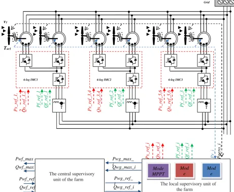
5 Supervision of the Active and Reactive Powers of a Wind Farm
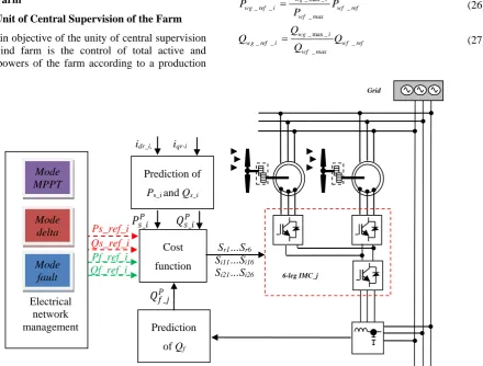
5.1 The Unit of Central Supervision of the Farm
The main objective of the unity of central supervision of the wind farm is the control of total active and reactive powers of the farm according to a production
plan called each time by the network manager [11,12,28]. On the one hand, this unit receives power demand (Pwf_ref, Qwf_ref) of network manager. On the other hand, it sends to the electrical network the information on the maximum capacity of production power (Pwf_max, Qwf_max), where the production capacity of the active power of the farm is evaluated by summing all maximum active power available at each turbine of the wind farm.
_ max _ max_ 1
n
wf wg i
i
P P
(24)Similarly, the production capacity of the reactive power of the farm is estimated by summing all maximum reactive power that can produce each turbine of the wind farm.
_ max _ max_ 1
n
wf wg i
i
Q Q
(25)By adopting the algorithm of proportional distribution, the reference powers for each wind turbine (Pwg_ref_i,
Qwg_ref_i) are calculated using (26) and (27). These will be sent in real time to the local supervision of each turbine units.
_ max _
_ _ _
_
wg i
wg ref i wf ref
wf max
P
P P
P
(26)
_ max _
_ _ _
_
wg i
wg ref i wf ref
wf max
Q
Q Q
Q
(27)
6-leg IMC_j Ps_ref_i
Qs_ref_i Pf_ref_i Qf_ref_i
Mode MPPT
Mode delta
Mode fault
Electrical network management
Grid
Cost function
Sr1…Sr6
Si11…Si16
Si21…Si26
Prediction of Qf
idr_i, iqr-i
𝑄𝑓_𝑗𝑃
Prediction of
Ps_i and Qs_i
𝑃𝑠_𝑖𝑃 𝑄𝑠_𝑖𝑃
Fig. 3 Proposed control scheme for the two DFIGs fed by an indirect matrix converter.
Iranian Journal of Electrical & Electronic Engineering, Vol. 14, No. 3, September 2018 252
5.2 Local Supervisory Controller Unit of a Wind Generator
The Algorithm of local supervision is proposed to distribute active and reactive power between wind generators [13]. The mains objectives of this algorithm are:
Distribute the active and reactive powers in proportional way and do not cause the saturation of some wind turbines while the others are able to provide more active or reactive power.
From the safety aspect, the algorithm ensures that each wind generator will work far enough from the limit of reactive power generation.
6 Simulation Results
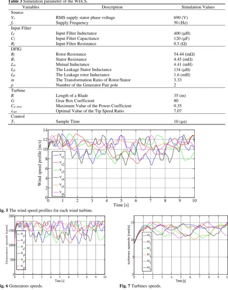
The overall structure of a wind farm based on six leg indirect matrix converters connected to the electric network is shown in Fig. 4 (wind farm with 10 MW). It consist of six doubly fed induction generators with same nominal power 2 MW whose parameters are given in
the Table 2, each rotor of the DFIGs assembly with wind turbine via a gear box, each turbine received different variable wind speed profile. The other side of the rotor connected to only one inverter stage in order to control the power flow by controlling the rotor currents. In other side of the converter, the rectifier stage includes an RLC filter at the input, which is necessary to prevent over voltages caused by the high frequency switching of the input stream produced by the switching and inductive nature of the load. The proposed predictive control and supervisory algorithm for WECS of Fig. 4 is tested in MATLAB environment with a sampling time of 10 μs.
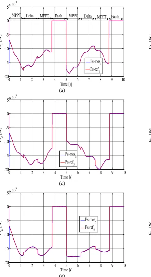
The product active and reactive powers by the wind farm are illustrated by Fig. 8 in the left and in the right respectively, for a reactive power reference settled to 0 VAR before 3.2 s and -2.5e5 and -7.5e5 VAR after
3.2 s. The tracking performance shows high dynamic performance for both stator powers since
v1
Tur1
6-leg IMC1 6-leg IMC2 6-leg IMC3
Paer
o_
i
Pr
_i
Pwf_ref
Qwf_ref Pwf_max
Qwf_max
Pwg_ref_ i
Qwg_ref_i Pwg_max_ i
Qwg_max_i
Ps
_r
ef_i
Qs_r
ef_i
Pf
_r
ef_i
Qf_r
ef_i
Mode MPPT
Mod e delta
Mod e fault
The central supervisory unit of the farm
The local supervisory unit of the farm
Qf_r
ef_3
Pf
_r
ef_3
Ps
_r
ef_5,6
Qs_r
ef_5,6
Qf_r
ef_
2
Pf
_r
ef_2
Ps
_r
ef_3,4
Qs_r
ef_3,4
Qf_r
ef_1
Pf
_r
ef_1
Ps
_r
ef_1,
2 Qs_r
ef_1,2
Grid
Fig. 4 Proposed control scheme for the two DFIGs fed by an indirect matrix converter.
Iranian Journal of Electrical & Electronic Engineering, Vol. 14, No. 3, September 2018 253 the powers are perfectly decoupled and track their
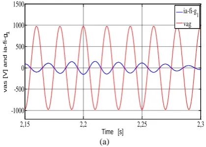
references accurately and precisely. Also the reactive power is achieved with good dynamic performance as shows in Figs. 9 and 10 tacking into count the capability of the wind generator and the power converter. As a consequence, the filter current shown in Fig. 12 appears highly sinusoidal and is achieved in opposite where the
reactive power of the wind farm set to 0 or different in phase with the grid voltage when the reactive power set the negative value (Qwf < 0) corresponding the functioning of the wind generator.
In Fig. 11, we illustrate the rotor line currents versus the wind speed profile for both sub synchronous and super synchronous regimes.
Table 3 Simulation parameter of the WECS.
Variables Description Simulation Values
Source
Vs RMS supply stator phase voltage 690 (V)
fs Supply Frequency 50 (Hz)
Input Filter
Lf Input Filter Inductance 400 (μH)
Cf Input Filter Capacitance 120 (μF)
Rf Input Filter Resistance 0.5 (Ω)
DFIG
Rf Rotor Resistance 54.44 (mΩ)
Rs Stator Resistance 4.45 (mΩ)
Lm Mutual Inductance 4.41 (mH)
Lfs The Leakage Stator Inductance 134 (μH)
Lfr The Leakage rotor Inductance 1.6 (mH)
m The Transformation Ratio of Rotor/Stator 3.33
p Number of the Generator Pair pole 2
Turbine
R Length of a Blade 35 (m)
G Gear Box Coefficient 80
Cp_max Maximum Value of the Power Coefficient 0.35
λopt Optimal Value of the Tip Speed Ratio 7.07
Control
Ts Sample Time 10 (μs)
0 1 2 3 4 5 6 7 8 9 10
0 2 4 6 8 10 12 14
Time [s]
W
in
d
s
p
e
e
d
p
ro
fi
le
[m
/s
]
v t1 v
t2 v
t3 v
t4 v
t5 v
t6
Fig. 5 The wind speed profiles for each wind turbine.
0 1 2 3 4 5 6 7 8 9 10
0 500 1000 1500 2000
Time [s]
G
e
n
e
ra
to
rs
s
p
e
e
d
s
[rp
m
]
wg1 wg2 w
g3
w
g4
wg5 w
g6
0 1 2 3 4 5 6 7 8 9 10
0 5 10 15
Time [s]
tu
r
b
in
e
s sp
e
e
d
s [
r
a
d
/s]
wt
1
wt2 wt
3
wt4 wt
5
wt6
Fig. 6 Generators speeds. Fig. 7 Turbines speeds.
Iranian Journal of Electrical & Electronic Engineering, Vol. 14, No. 3, September 2018 254
0 1 2 3 4 5 6 7 8 9 10
-12 -10 -8 -6 -4 -2 0
x 106
Time [s]
A
cti
v
e
po
w
er
o
f
the
w
ind
fa
rm
[W]
P
wf-mes
P
wf-ref
MPPT
MPPT Delta Fault MPPT Delta MPPT Fault
0 1 2 3 4 5 6 7 8 9 10
-2.5 -2 -1.5 -1 -0.5 0 0.5x 10
6
Time [s]
Qwf
[V
A
R
]
Qwf-mes Qwf-ref Qwf-max
(a) (b)
Fig. 8 Powers product by wind farm: a) Active power and b) reactive power.
0 1 2 3 4 5 6 7 8 9 10
-20 -15 -10 -5 0 5x 10
5
Time [s]
Ps
1
[W
]
Ps-mes
1
Ps-ref
1
MPPT MPPT MPPT
MPPT Delta Fault Delta Fault
0 1 2 3 4 5 6 7 8 9 10
-20 -15 -10 -5 0 5x 10
5
Time [s]
Ps
2
[W
]
Ps-mes
2
Ps-ref
2
(a) (b)
0 1 2 3 4 5 6 7 8 9 10
-20 -15 -10 -5 0 5x 10
5
Time [s]
Ps
3
[W
]
Ps-mes
3
Ps-ref
3
0 1 2 3 4 5 6 7 8 9 10
-20 -15 -10 -5 0 5x 10
5
Time [s]
Ps
4
[W
]
Ps-mes
4
Ps-ref
4
(c) (d)
0 1 2 3 4 5 6 7 8 9 10
-20 -15 -10 -5 0 5x 10
5
Time [s]
Ps
5
[W
] Ps-mes5
Ps-ref
5
0 1 2 3 4 5 6 7 8 9 10
-20 -15 -10 -5 0 5x 10
5
Time [s]
Ps
6
[W
] Ps-mes
6
Ps-ref
6
(e) (f)
Fig. 9 The active power product by each turbine.
Iranian Journal of Electrical & Electronic Engineering, Vol. 14, No. 3, September 2018 255
0 1 2 3 4 5 6 7 8 9 10
-3 -2 -1 0 1x 10
5
Time [s]
Qs
1
[V
A
R] Qs-mes
1
Qs-ref
1
Qs-max
1
0 1 2 3 4 5 6 7 8 9 10
-3 -2 -1 0 1x 10
5
Time [s]
Qs
2
[V
A
R]
Qs-mes
2
Qs-ref
2
Qs-max
2
(a) (b)
0 1 2 3 4 5 6 7 8 9 10
-3 -2 -1 0 1x 10
5
Time [s]
Qs
3
[V
A
R] Qs-mes3
Qs-ref
3
Qs-max
3
0 1 2 3 4 5 6 7 8 9 10
-3 -2 -1 0 1x 10
5
Time [s]
Qs
4
[V
A
R] Qs-max
4
Qs-mes
4
Qs-ref
4
(c) (d)
0 1 2 3 4 5 6 7 8 9 10
-3 -2 -1 0 1x 10
5
Time [s]
Qs
5
[V
A
R]
Qs-mes
5
Qs-ref
5
Qs-max
5
0 1 2 3 4 5 6 7 8 9 10
-3 -2 -1 0 1x 10
5
Time [s]
Qs
6
[V
A
R]
Qs-mes
6
Qs-ref
6
Qs-max
6
(e) (f)
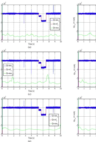
Fig. 10 The reactive power product by each turbine.
0 1 2 3 4 5 6 7 8 9 10 -5
-4 -3 -2 -1 0 1x 10
5
Time [s]
Q
fi1
[V
A
R]
Qfi-mes
1
Qfi-max1 Qfi-ref1
0 1 2 3 4 5 6 7 8 9 10 -5
-4 -3 -2 -1 0 1x 10
5
Time [s]
Q
fi2
[V
A
R]
Qfi-mes2 Qfi-ref2 Qfi-max
2
0 1 2 3 4 5 6 7 8 9 10 -5
-4 -3 -2 -1 0 1x 10
5
Time [s]
Q
fi3
[V
A
R]
Qfi-mes3 Qfi-max3 Qfi-ref
3
(a) (b) (c)
Fig. 11 The reactive power product by the filter side.
Iranian Journal of Electrical & Electronic Engineering, Vol. 14, No. 3, September 2018 256
0 1 2 3 4 5 6 7 8 9 10
-1000 -500 0 500 1000 1500 2000
Time [s]
R
o
to
r
curren
ts
[A
]
a
nd
Gener
a
to
r
s
peed
[tr/
m
in]
Generator speed synchrounous speed
Fig. 12 Rotor currents versus speed generator variations.
2,15 2,2 2,25 2,3
-1000 -500 0 500 1000 1500
Time [s]
va
s [
V
]
a
n
d
ia
-
fi-g1
ia-fi-g1 vag
6.6 6.62 6.64 6.66 6.68 6.7 6.72 6.74 6.76 6.78 6.8 -1000
-500 0 500 1000 1500
Time [s]
va
s [
V
]
a
n
d
ia
-
fi-g1
ia-fi-g
1
vag
(a) (b)
Fig. 13 Filter current: a) Qwf = 0 and b) Qwf < 0.
The wind farm functioning with three modes of control powers. First, the farm operates in “MPPT” mode to provide a maximum active power to the grid. Next, the control mode “reserve power” is determined by the network manager in order to participate the farm, the frequency adjustment if it deviates from its value (50 Hz). Finally, an unexpected mode called “default” mode, which simulates a failure in the power grid is occurred. During the first two modes, the active powers supplied by wind turbines, are subject to the control laws corresponding to each of these modes. However, the management of reactive is governed by proportional distribution algorithm to distribute the reactive power on three wind farm. When a fault occurring on the network, the stator of the DFIG wind turbines remain connected to the network by absorbing active and reactive power, while the rotor is short-circuited by the crow-bar. In this case, the wind turbines do not participate in the provision of the reactive power.
7 Conclusions
The paper presents a predictive direct power control of wind energy conversion system using a DFIG machine feeding by a six leg indirect matrix converter. The flexibility of predictive control strategy allows the tracking of the references of each sub-system (active and reactive power of a tow DFIGs and the reactive power in the filter side) with good performance and high effectiveness. The predictive algorithm avoids the use of any linear or nonlinear controllers in inner loops
except for the external speed loop. The control scheme is simple and extremely powerful since it uses a discrete model of the converter to predict the behavior of the system. It provides fast dynamic response for the power references where the network manager changes the control mode. The optimal suited converter switching state is obtained from the 192 possible combinations by considering a cost function that includes the power errors. The supervisory proportional algorithm is used to ensure that each wind generator works far enough from its maximum power production capability.
Simulation results shows an accurate and precise tracking performance; The FS-MPC method shows that multiple objectives can be obtained simultaneously by adding more terms in the global cost function. Also supervisory proportional algorithm allows a good distribution of reactive power reference taking into account the reactive power capability.
References
[1] M. Lopez, M. Rivera, C. Garcıa, J. Rodriguez, R. Pena, J. Espinoza and P. Wheeler, “Predictive control of two parallel induction machines fed by a six-leg indirect matrix converter under an unbalanced ac-supply,” IEEE International Symposium on Sensorless Control for Electrical Drives and Predictive Control of Electrical Drives and Power Electronics (SLED/PRECEDE), 2013.
Iranian Journal of Electrical & Electronic Engineering, Vol. 14, No. 3, September 2018 257 [2] M. Lopez, C. Garcia, J. Rodriguez, M. Rivera,
R. Pena, J. Espinoza and P. Wheeler, “Predictive torque control of a multi-drive system based on a two-stage six-leg matrix converter with unity input power factor,” Fourth International Conference on Power Engineering, Energy and Electrical Drives (POWERENG), 2013.
[3] M. Lopez, M. Rivera, C. Garcia, J. Rodriguez, R. Pena, J. Espinoza and P. Wheeler, “Predictive torque control of a multi-drive system fed by a six-leg indirect matrix converter,” International Conference on Industrial Technology (ICIT), pp. 1642–1674, 2013.
[4] A. D. Hansen, P. Sorensen , F. Iov and F. Blaabjerg, “Centralised power control of wind farm with doubly fed induction generators,” Renewable Energy, Vol. 33, No. 7, pp. 935–951, 2006.
[5] A. Tapia, G. Tapia, J. X. Ostolaza, J. R. Saenz, R. Criado and J. L. Berasategui, “Reactive power control of a wind farm made up with doubly fed induction generators,” in IEEE Power Tech Proceedings, Porto, Portugal, 10-13 Sep. 2001. [6] P. Cartwright, L. Holdsworth, J. B. Ekanayake and
N. Jenkins, “Coordinated voltage control strategy for a doubly fed induction generator (DFIG)-based wind farm,” in IEE Proceedings-Generation, Transmission and Distribution, Vol. 151, No. 4, pp. 495–502, 2004.
[7] S. Skolthanarat, The modeling and control of a wind farm grid interconnection in a multi-machine system. Ph.D. Dissertation, Virginia Polytechnic Institute and State University, 2009.
[8] V. Courtecuisse, B. Robyns, B. Francois, M. Petit and J. Deuse, “Variable speed wind generators participation in primary frequency control,” Wind Engineering, Vol. 32, No. 3, pp. 299–318, 2008. [9] T. Ghennam, K. Aliouane, F. Akel, B. Francois and
E. M. Berkouk, “Advanced control system of DFIG based wind generators for reactive power production and integration in a wind farm dispatching,” Energy Conversion and Management, Vol. 105, pp. 240– 250, Nov. 2015.
[10]F. Merahi, E. M. Berkouk and S. Mekhilef, “New management structure of active and reactive power of a large wind farm based on multilevel converter,”
Renewable Energy, Vol. 68, pp. 814–828, Aug. 2014,
[11]G. Foo and F. M. Rahman, “Direct torque and flux control of an IPM synchronous motor drive using a back stepping approach,” IET Electric Power Applications, Vol. 3, No. 5, pp. 413–421, 2009.
[12]M. A. Bevilaqua, A. Nied and J. Oliveira, “Labview FPGA FOC implementation for synchronous Permanent Magnet Motor Speed Control,” in 11th EEE/IAS International Conference
on Industry Applications (INDUSCON), Juiz de Fora, Brasil, Dec. 2014.
[13]C. T. Kowalski, J. Lis and T. Orlowska-Kowalska, “FPGA implementation of DTC control method for induction motor drive,” in The International Conference on Computer as a Tool, Warsaw, Poland, pp. 1916–1921, 2007.
[14]M. Denpenbrock, “Direct Self Control DSC of inverter fed induction machine,” Power Electronics Specialists Conference, Blacksburg, VA, USA, pp. 632–641, Jun. 1987.
[15]S. Chikha, K. Barra and A. Reama, “Predictive current control of a wind energy conversion system based DFIG via direct matrix converter,” 6th
International Renewable Energy Congress (IREC), pp. 1–7, 2015.
[16]S. Chikha and K. Barra, “Predictive Control of Variable Speed Wind Energy Conversion System with Multi Objective Criterions,” Periodica Polytechnica Electrical Engineering and Computer Science, Vol. 60, No. 2, pp. 96–106, 2016.
[17]S. El Aimani, “Modelling and control structures for variable speed wind turbine,” in International Conference on Multimedia Computing and Systems (ICMCS), pp 1–5, Apr. 2011.
[18]T. Mesbahi, T. Ghennam and E. M. Berkouk, “A Doubly Fed Induction Generator for wind stand-alone power applications (Simulation and experimental validation),” in XXth International
Conference on Electrical Machines (ICEM), pp. 2028–2033, Sep. 2012.
[19]Bouharchouche, E.M. Berkouk, T. Ghennam and B. Tabbache, “Modeling and control of a Doubly fed induction generator with battery-supercapacitor hybrid energy storage for wind power applications,” in Fourth International Conference on Power Engineering, Energy and Electrical Drives (POWERENG), pp. 1392–1397, May 2013.
[20]M. Lopez, J. Rodriguez, C. Silva and M. Rivera, “Predictive Torque Control of a Multi-Drive System Fed by a Dual Indirect Matrix Converter,” IEEE Transactions On Industrial Electronics, Vol. 62, No. 5, May 2015.
[21]V. Yaramusu and B, Wu, Model predictive control of wind energy conversion systems. First edition, John Wiley & Sons, 2017.
Iranian Journal of Electrical & Electronic Engineering, Vol. 14, No. 3, September 2018 258 [22]T. Hadjina, I. Mišković and M. Baotić, “Finite
control set model predictive control of a grid connected two-level converter,” in 19th International
Conference on Electrical Drives and Power Electronics (EDPE), 2017.
[23]T. Geyer, “Model predictive control of high power converters and industrial drives,” Energy Conversion Congress and Exposition (ECCE), 2017. [24]A. El Kachani, A. A. Laachir, T. Jarou and A. Hadjoudja, “Nonlinear model predictive control applied to a DFIG-based wind turbine with a Shunt APF,” International Renewable and Sustainable Energy Conference (IRSEC), pp. 369–375, 2017. [25]J. Rodriguez, J. Kolar, J. Espinoz, M. Rivera and
C. Rojas, “Predictive torque and flux control of an induction machine fed by an indirect matrix converter with reactive power minimization,”
International Symposium on Industrial Electronics, Bari, pp. 3177–3183, 2010.
[26]R. Vargas, J. Rodriguez, U. Ammann and P. Wheeler, “Predictive Current Control of an Induction Machine Fed by a Matrix Converter with Reactive Power Control,” IEEE Transactions on Industrial Electronics, Vol. 55, No. 12, pp. 4362– 4371, Jun. 2008.
[27]H. Amaris, M. Alonso and C. A. Ortega, Reactive Power Management of Power Networks with Wind Generation. Springer Science & Business Media, 2013.
S. Chikha received his B.Sc. degree in
Electrical Engineering in 2002, after he received his Engineering degree in Electrical Engineering option control of electrical machine from University of Mohemd Khider Biskra in 2008. He received his Magister and Ph.D. degree in Electrical Engineering in December 2011 and July 2017, respectively from University of Larbi Ben M'hidi Oum El Bouaghi. Now he is a Professor at University of Echahid Hamma Lekhder El oued. His current research interests include renewable energy system, high power converters, and predictive control.
© 2018 by the authors. Licensee IUST, Tehran, Iran. This article is an open
access article distributed under the terms and conditions of the Creative
Commons Attribution-NonCommercial 4.0 International (CC BY-NC 4.0)
license (https://creativecommons.org/licenses/by-nc/4.0/).

![Table 2 Comparison of linear control with PI regulator and SVM, and MPC [22].](https://thumb-us.123doks.com/thumbv2/123dok_us/24034.2002636/5.595.53.545.628.751/table-comparison-linear-control-pi-regulator-svm-mpc.webp)