7508/tpnms.2016.02.002
Effect of Inserting Coiled Wires in Tubes on the Fluid Flow and Heat Transfer
Performance of Nanofluids
H. Safikhani1,*, A.R. Zare Mehrjardi1, M. Safari2
1Department of Mechanical Engineering, Faculty of Engineering, Arak University, Arak 38156-88349, I. R.Iran
2Department of Mechanical Engineering, Isfahan University of Technology, Isfahan 84156-83111, I. R. Iran
Received 4 April 2015; revised 21 May 2015; accepted 25 May 2015; available online 28 June 2016 ABSTRACT: In the present study, numerical study of Al2O3-water nanofluid flow in different coiled wire inserted tubes are performed
to investigate the effects of inserting coiled wires in tubes on the fluid dynamic and heat transfer performance ofv nanofluids. The numerical simulations of nanofluids are performed using two phase mixture model. The flow regime and the wall boundary conditions are assumed to be laminar and constant heat flux respectively. The effects of inserting coiled wires in tubes on different parameters such as heat transfer coefficient, pressure drop, temperature distribution, velocity distribution and secondary flows are presented and discussed. The results show that using coiled wire in tubes leading to increase in ℎ about 13.44% but increase the Δp about 14.66% with respect to the flow without nanofluid and coiled wire. Similarly, using nanofluid leading to increase in ℎ about 5.52% but increase the Δp about 8.92%. Finally, using both of the mentioned heat transfer enhancement mechanisms leading to increase in ℎ about 17.51% but increase the value of Δp about 22.86%.
KEYWORDS: CFD; Coiledwires; Mixture model; Nanofluid; Two phase model
Introduction
Heat Transfer Enhancement (HTE) in the tubes used in various industrial applications and consequently reducing the volume of industrial equipment is a subject that has been investigated by engineers and researchers for many years. In general, the heat transfer enhancing methods can be divided into active and passive approaches; which the passive method, due to its ease of use and lower cost, has greatly attracted the attention of the researchers and engineers. An important and useful way of passively enhancing the amount of heat transfer in tubes is the use of a nanofluid instead of base fluid. A nanofluid refers to a compound in which solid, and mostly metallic, particles at nano sizes (usually less than 100 nm) are added to an ordinary fluid and help increase the value of the mixture conductivity and thus improve the amount of heat transfer in that fluid. Due to a considerable enhancement of heat transfer and a negligible pressure drop achieved by nanofluids, relative to base fluids, the use of nanofluids has become very commonplace in recent years [1-7]. Das et al. [1] experimentally investigated the effects of different parameters (e.g., temperature, nanoparticle volume fraction, etc.) on the thermal conductivity of nanofluids. They ultimately presented a relation for thermal conductivity of nanofluids as a function of temperature, nanoparticle volume fraction, etc.
*Corresponding Author Email: [email protected]
Tel.: +988632625726; Note. This manuscript was submitted on April 4, 2015; approved on May 21, 2015; published online June 28, 2016.
In addition to costly experimental studies, the numerical simulation of nanofluids using Computational Fluid Dynamics (CFD) techniques is another effective approach in analyzing the performance of nanofluids [4, 5]. In general, for the numerical simulation of nanofluids, there are two methods called the single-phase and two-phase, with the two-phase method being much more exact [6]. The two-phase method itself has different categories, including the Eulerian-Eulerian method, mixture method, etc. Using the three methods of phase Eulerian-Eulerian, two-phase mixture, and single-two-phase homogeneous, Lotfi et al. [7] simulated the Al2O3-water nanofluid flow in circular tubes. By comparing the simulation results with the experimental data, they came to the conclusion that the two-phase mixture method is the most exact method among the existing approaches. In this article also, the two-phase mixture method is used for the numerical simulation of nanofluid flow in coiled wire inserted tubes.
The other method to enhance the heat transfer value is using tube inserts like twisted tapes, brushes, and coiled wires. Due to low cost and their capability for easy installing or removing inside the tubes (for cleaning purposes), the coiled wire inserts usage is growing [8]. Some researchers have studied heat transfer and pressure drop during forced convection in tubes with inserts. Salimpour and Gholami [8] used coiled wires to augment heat transfer coefficient in condensation of R-404A vapor. Kumar et al. [9] studied heat transferenhancement during
C i R d e t e t p n a v e p h i a t e o o D o ( r t t i i h Nom a Acce Cp Speci Cf Skin C Cons d Coil d D Tube dp Diam g Gravi h Local Gr Grash k Therm kB Boltz
L Leng Nu
Nusse p
Coil p Pr Prand Heat Re Reyn Condensation inserted tube. R-134a in hori developed a ne Salimpour an enhanced hea twisted tape in experimentally tape inside h pressure drop nominal area b augment heat vapor. Akhava experimental pressure drop horizontal tube insertion of h augments the p to the plain tub Eiamsa-ard experimental a of using multip on the heat tra Despite the lar of tube inserts (boiling and c research which transfer perfor tubes using C study of Al2O3 inserted tubes inserting coile heat transfer p
enclature
leration (m s-2) ific heat (J kg-1
friction coeffici tant in Eq. (14) diameter (m)
diameter (m) meter of nanopar
itational acceler l heat transfer c hof number (=g mal conductivit zmann constant th of tubes (m) elt Number (=h pitch (m) dtl number (=αm
flux (W m-2) nolds number (=
of R-22 insi Hejazi et al. [1 izontal tubes e ew correlation nd Yarmohamm at transfer and nserted tubes d y. They observ horizontal tub up to 239% basis. Agrawal transfer coeffi an-Behabadi e studies on he p increase of es with spring elically coiled pressure loss fr be values.
and Kiatki and numerical
ple twisted tap ansfer and fluid rge amount of s on the nanof condensation), h investigate th rmance of nano CFD study. In
3-water nanoflu are performe ed wires in tu erformance of
K-1) ient
rticles (m) ration (m s-2) coefficient (W/m gβmq"D4h/kmν2m)
ty (W m-1 K-1) (=1.3807
10-hDh/k)
m/νm) =VDh/νm)
ide a horizon 10] studied the equipped with t for prediction madi [11, 12 d increased p during condens ved that the ins bes increases
compared to p et al. [13] use ficient in conde
et al. [14, 15] eat transfer e
R-134a cond inserts. They o d wires inside from 260% to 1
ttipong [16] study to inve pes with differ d flow of TiO2-f research devo fluid flow and
it is noted th he details of flu ofluids in coi n the present uid flow in diff
d to investiga bes on the flu
nanofluids.
H.
m2K) ) -23 J K-1)
ntal twisted ta e condensation
twisted tapes a of pressure dro 2] reported bo pressure drop ation of R-404 sertion of twist the condensi plain tubes on ed coiled wires
ensation of R-] performed tw
nhancement a densation insi observed that t horizontal tub 1600% compar
performed stigate the eff ent configurati -water nanoflu oted to the eff d two-phase flo hat there is no
uid flow and h iled wire insert
study, numeri ferent coiled w ate the effects
uid dynamic a
Safikhani et al.
B d ape n of and op. oth of 4A, ted ing n a s to -22 wo and ide the bes red an fect ion uid. fect ow t a eat ted cal wire of and Mathe Geome The coiled diamete shown i Mixtur In th perform phase a spatial velocity certain utilizing it solve for the nanopa The eq flow ar Co
T Temperat Greek Sy
β thermal ex
ε porosity
η similarity
λ transverse ζ dimension
θ dimension
μ dynamic v
ν kinematic
ρ Density (k
σ electric co
φ nanoparti
ψ streamline Subscript BF Base fluid
dr Drift
f Fluid
i Inlet cond
ematical mod
etry
geometry of p wire inserted er. The schem
in Figure 1.
Fig. 1. The schem
re model he present study med using mixt approach. This length scales. y field, and in
fraction of ba g the governin es the continu e mixture, an articles.
quations for th re: ontinuity: ture (K) ymbols xpansion coeffi y variable e curvature nlessstreamwise nless temperatu viscosity (kg m c viscosity (m2s
kg m-3) onductivity s cle volume frac e function r ts
d
ditions
delling
present simula tubes with d matic of a coile
matic geometry of
y, numerical st ture model wh s method inves In this method n a given con ase fluid and n ng equations o
ity, momentum d the volume
he steady stat
icient (K-1)
2ξ Re⁄ ⁄ e coordinate ure
m-1 s-1) -1)
A m kg ction
r ν u x ⁄ f ξ
ations contains different coil ed wire inserte
considered proble
tudy of nanoflu hich is a single stigates equilib d each phase h ntrol volume nanoparticles. of each phase s
m and energy e fraction equ
te conditions x r⁄
ξ, η
s different and pitch ed tube is
em
uid flow is e fluid two brium over has its own there is a Instead of separately, equations uation for
0
)
V
.(
m m
(1) Momentum:
, , ,
1
.( ) .( ) .
( ) ( )
m m m m m
n
k k dr k dr k m i m i k
V V P V
V V g T T
(2) Energy:
) T k .( )) P H ( V
.( n m
1 k
k k k
k
(3) Volume fraction:
)
V
.(
)
V
.(
P
P m
P
P dr,P
(4)Where Vm is the mass average velocity:
m n
1 k
k k k
m
V
V
(5)In equation 2, Vdr,k is the drift velocity for nanoparticles:
m k k ,
dr
V
V
V
(6)The slip velocity (relative velocity) is calculated as the velocity of nanoparticles relative to the velocity of base fluid:
f p
pf
V
V
V
(7)The relation between drift velocity and relative velocity is as follows:
fk n
1
k m
k k pf
p ,
dr
V
V
V
(8)
The relative velocity and drag function are calculated using Manninen et al. [17] and Schiller and Naumann [18] relations respectively, as follows:
a ) (
f 18
d V
P m P
drag f
2 P P
pf
(9)
1000 Re
for Re
0183 . 0
1000 Re
for Re
15 . 0 1 f
P P
P 687
. 0 P
drag (10)
The acceleration (a) in equation 9 is
m m
.
)
V
V
(
g
a
(11)Nanofluid mixture properties
The mixture properties for Al2O3-water nanofluid are calculated based on following expressions:
Density [19]:
f p
m (1 )
(12)
Specific heat capacity [20]:
f p p
p m
p ) ( C ) (1 )( C )
C
( (13)
Dynamic viscosity [21]:
C
72
d
V
2p B p f
m
(14)Where VB and δ are the Brownian motion of
nanoparticles and the distance between nanoparticles respectively and is calculated from:
p p
B
p B
d
T
k
18
d
1
V
(15)p
3
d
6
(16)C in equation 14 is defined as:
f
4 p 3 2
p
1d C ) (C d C )
C ( C
(17)
Where C1, C2, C3 and C4 are given as:
000000393 .
0 C , 00000009 .
0 C
000002771 .
0 C , 000001133 .
0 C
4 3
2 1
(18)
Thermal conductivity [22]:
0.7460 0.3690 0.7476
0.9955 1.2321
1 64.7 ( ) ( )
Pr Re
f p
m
f p f
f f
d k
k
k d k (19)
H. Safikhani et al.
f 2 B f
3
T
k
Re
(20)f f f
Pr
(21)
Where λf is the MFP (mean free path) of water molecular
(λf = 0.17 nm), kB is Boltzmann constant (kB= 1.3807 × 10⁻²³
J/K) and η can be defined by the following equation:
5 .10 , 2.414 10 , 247.8, 140
B T C
A A
B C
(22)
Thermal expansion coefficient [23]:
f
f p f
p
p f m
1
1
1
)
1
(
1
1
(23)Boundary conditions
For numerical simulation, the equations of previous sections should be solved subject to the following boundary conditions:
Tubes inlet:
0
V
V
,
V
V
m,z
i m,x
m,y
(24a)i
T
T
(24b)i
(24c) Fluid-wall interface:
0 V V
Vm,x m,y m,z (25a)
w m w
n T k q
(25b)
Tubes outlet: Zero gradient is applied to hydrodynamic variables and constant gradient is applied to temperature [4-5, 24]:
Numerical methods
The numerical study is performed using the finite volume method. A second order upwind method is used for the convective and diffusive terms and the SIMPLE algorithm
is employed to solve the coupling between the velocity and pressure fields.
To make sure that the obtained results are independent of the size and the number of generated grids, several grids with different sizes along the axial, radial and angular directions has been tested for each coiled wire inserted tube; and it has been attempted to consider for each tube the best grid, with the highest accuracy and the lowest computation cost.
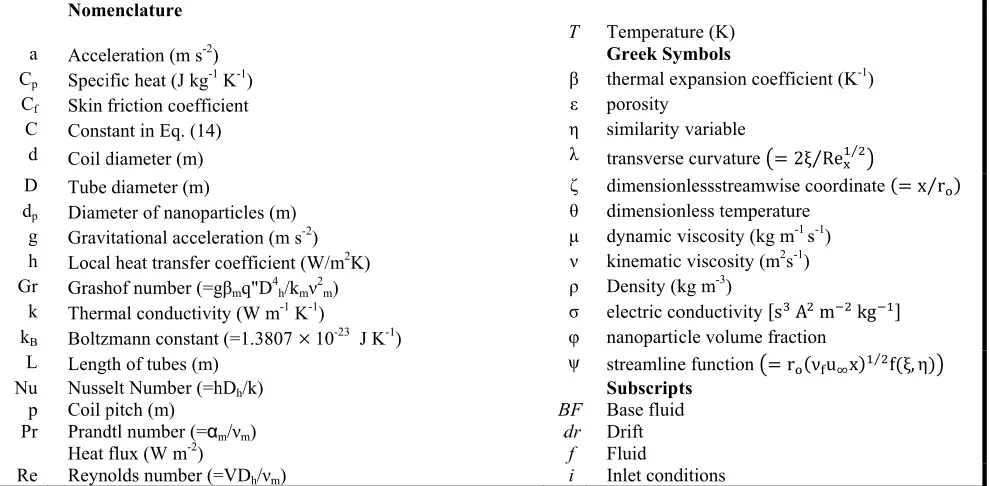
The investigated tubes contain between 2 and 3 million elements. Figure 2 shows a sample of grid generation for coiled wire inserted tubes.
Fig. 2. The schematic geometry of considered problem
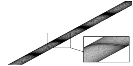
Validations
To attain the confidence about the numerical study, it is necessary to compare the results with the available data. Figure 3 compares the local heat transfer coefficient (h) and local friction factor (Cf) for a plain tube without coiled wire
of present study with the available data of Mirmasoumi and Behzadmehr [25] and Shariat et al. [26]. As is evident from this figure the present simulations agree well with the available data.
RESULTS
Numerical simulations of Al2O3-water nanofluid flow are performed in different coiled wire inserted tubes to investigate the effects of inserting coiled wires in tubes on the fluid dynamic and heat transfer performance of nanofluids.
Effect of different enhancement mechanism
In heat exchangers the heat transfer coefficient and pressure drop are two important parameters and should be investigated simultaneously [5].
Therefore in the result section, heat transfer coefficient and pressure drop values of two different heat transfer enhancement mechanisms namely using nanofluid and using coiled wire in tubes are presented and compared with each other.
t a a t i o u m t
E
f
Fig. 3. Comp simulation with t
Thermophysi
Physical prop J kg K⁄ kg m⁄ W m K⁄ 10 m
10 K
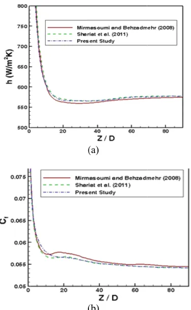
Finally, usin to increase in about 22.86% and coiled wir that increase o is more than th of pressure dro using coiled w mixing of flui tubes.
Effect of coil Effect of ch first row of Ta
(
(
parison of (a) h an the available data dp=10n
Ta
ical properties of par
Fluid (w perties
4 K
9 0 K
s ⁄ K
ng both of the m
ℎ about 17.51 with respect re. It is obv of heat transfer
hat of using n op due to usin wire. The reas id inside tube
l diameter hanging on t able 2 (definitio
(a)
(b)
nd (b) Cf of the pre
for a plain tube (R m,Φ=2%)
able 1
f the working flu rticle.
Na d phase
ater)
4179 997.1 0.613 1.47
21
mentioned mec % but increase to the flow w vious from the r value due to u anofluid and s ng nanofluid is son of this pr es due to usin
he ℎ and Δp, ons of d, D an
esent numerical Re=300, Gr=90000
uid and the nano
ano particle (Cu
385 8933
400 1163.1
1.67
chanisms leadi e the value of without nanoflu
e mentioned d using coiled w similarly increa
less than that roblem is grea g coiled wire
are shown in t d p are present
0,
o
u)
ing Δp uid ata wire ase of ater in
the ted
in Figur the tem section
Fig. 4.
Fig.
As sho 0.05 to increase It see idea fo pressur pressur obvious fluid te greater Seco tube pla tubes. The s differen lower r of chan the out As it is strength
Effect Effec second changin the outl
ure 1). Moreove mperature and
are shown in F
. Effect of changin
5. Effect of chang
own in the firs o 0.015 leadin e the Δp about ems that using or increasing th
re drop value o re compensatio s from Figures emperature and
.
ondary flows o ay an effective
secondary flow nce between n regions of the t nging on the tlet sections of s obvious from hened due to u
of coil pitch ct of changing
row of Table ng on the tem let section are
er the detailed d velocity dist Figures 4 and 5
ng coil diameter on nanofluid flow
ging coil diameter nanofluid flow
st row of Tabl ng to increase
t 7.16%. g coiled wire w
he heat transf of this idea can on device such s 4 and 5 that d fluid velocit
or secondary v e role in the am
ws are create nanofluid den tube [26]. Figu secondary vec f different coi m this figure, th
using coiled wir
g on the ℎ a e 2. Moreover mperature and shown in Figu
effects of chan tributions at 5 respectively.
n temperature distr w
on velocity distrib w
le 2, increase in ℎ about 3
with higher fer value and t n be compensa as pump. Mor t the maximum ty is strengthe
velocity vector mount of heat t
ed as a resu sities in the u ure 6 illustrates
ctors of the na iled wire inser he secondary v res with greate
and Δp are sho r the detailed velocity distri ures 7 and 8 res
nging on the outlet
ribution in
bution in
in from 3.02% but
is a good the higher ated with a reover it is m value of ened using
rs inside a transfer in
ult of the upper and s the effect anofluid at rted tubes. vectors are er .
Effect of di
Effect of
Variable Va
D d 0 0 0 D p Re 1 3 5 (%) 1 ) nm ( dP 2 4 1 Gr 45 90 135
Fig. 6. Effect o
Fig. 7. Effect
Fig. 8. Effe
Tab
fferent paramete coefficient an
alue (w/m2k)
0.05 544.06 0.10 550.11 0.15 560.50 5 550.11 10 541.25 13 523.78 100 477.57 300 550.11 500 614.78 0 489.42 1.5 550.11 3 591.32 20 561.48 40 550.11 100 525.94 5000 476.25 0000 550.11 5000 648.29
f changing coil dia in nano
of changing coil p nanof
ct of changing coi nanof
ble 2
ers on the averag nd pressure drop
) Changes in h (%)
0.00 1.11 3.02 0.00 -1.61 -4.78 0.00 15.18 28.73 0.00 12.40 20.82 0.00 -2.02 -6.32 0.00 15.50 36.12
ameter on seconda ofluid flow
pitch on temperatu fluid flow
il pitch on velocity fluid flow
H.
ge heat transfer . Δp(pa) Chang in Δp(% 9.91 0.00 10.05 1.41 10.62 7.16 10.05 0.00 9.83 -2.18 9.51 -5.37 8.94 0.00 10.05 12.4 11.35 26.9 9.84 0.00 10.05 2.11 10.19 3.52 10.09 0.00 10.05 -0.39 10.08 -0.09 10.01 0.00 10.05 0.39 10.11 0.99
ary velocity vector
ure distribution in
y distribution in
Safikhani et al.
ges %) 0 6 0 8 7 0 41 95 0 2 0 9 9 0 9 9 s
As s from 5 decreas wire wi transfer be com obvious fluid te using c Figure coiled w smaller greater Fig. 9 Conclu Al2O inserted the effe dynami two ph bounda regime. The leading about 1 and coi Simi 5.52% b of the leading of Δp a Incre more th pressur using c to incre 7.16%. Incre 4.78% b with gr the heat
shown in the s to 13 leadin se the Δp abo
ith smaller
r and the highe mpensated with
s from Figures emperature and coiled wires w 9, the second wires with gre r mixing of f
.
9. Effect of changin
usion O3-water nano
d tubes has be fects of insertin
ic and heat tra hase mixture ary condition
.
results show g to increase in
14.66% with r iled wire. ilarly, using na
but increase th mentioned he g to increase in about 22.86%.
ease of heat tra han that of usin re drop due to coiled wire. Inc
ease in ℎ abo
easing from but decrease th reater and sm at transfer value
second row of ng to decrease out 5.37%. It s is a good idea er pressure dro a device such s 7 and 8 that d fluid velocity with different
ary vectors are eater . The re fluid due to u
ng coil pitch on se nanofluid flow
fluid flow in een numericall ng coiled wire ansfer perform
model and c have been em
ed that using n ℎ about 13.4 respect to the
anofluid leadin he Δp about 8.9 eat transfer en
ℎ about 17.51
ansfer value du ng nanofluid a o using nanofl creasing from out 3.02% but
5 to 13 leading he Δp about 5 maller is a e and the highe
f Table 2, incr in ℎ about 4 seems that usi a for increasin op value of thi as pump. Mor t the maximum y does not chan . However as e weakened du eason of this p using coiled w
econdary velocity v w
n different co ly studied to i es in tubes on mance of nanof constant heat mployed in th
g coiled wire 44% but increa
flow without
ng to increase i 92%. Finally, u nhancement me % but increase
ue to using coil and similarly in luid is less tha m 0.05 to 0.01 t increase the
g to decrease i .37%. Using c good idea for er pressure dro
rease in 4.78% but
ing coiled ng the heat is idea can reover it is m value of nge due to shown in ue to using problem is wires with
vectors in
oiled wire investigate n the fluid fluids. The flux wall he laminar
in tubes ase the Δp
nanofluid
in ℎ about using both echanisms e the value
led wire is ncrease of an that of 15 leading Δp about
of this idea can be compensated with a pressure compensation device such as pump. The secondary vectors of nanofluid are strengthened due to using coiled wires with greater and smaller .
REFERENCES
[1] S. Das, N. Putra, P. Thiesen, R. Roetzel: Temperature dependence of thermal conductivity enhancement for nanofluids, J. Heat Transfer 125 (2003) 567-574.
[2] S. Murshed, K. Leong, C. Yang: A combined model for the effective thermal conductivity of nanofluids, Appl. Therm. Eng 29 (2009) 2477-2483.
[3] T. Teng, Y. Hung, T. Teng, H. Mo, H. Hsu: The effect of alumina/water nanofluid particle size on thermal conductivity, Appl. Therm. Eng 30 (2010) 2213-2218.
[4] H. Safikhani, A. Abbassi: Effects of tube flattening on the fluid dynamic and heat transfer performance of nanofluid flow, Adv. Powder Technolog 25 (3) (2014) 1132-1141.
[5] H. Safikhani, A. Abbassi, A. Khalkhali, M. Kalteh: Multi-objective optimization of nanofluid flow in flat tubes using CFD, Artificial Neural Networks and genetic algorithms, Adv. Powder Technolog 25(5) (2014) 1608-1617.
[6] M. Kalteh, A. Abbassi, M. Saffar-Avval, J. Harting: Eulerian–Eulerian two-phase numerical simulation of nanofluid laminar forced convection in a microchannel, Int. J. Heat Fluid Flow 32 (2011) 107–116.
[7] R. Lotfi, Y. Saboohi, A. Rashidi: Numerical study of forced convective heat transfer of Nanofluids: Comparison of different approaches, Int. Commun. Heat Mass Transfer 37 (2010) 74–78.
[8] M. R. Salimpour, H. Gholami: Effect of inserting coiled wires on pressure drop of R-404A condensation, International Journal of Refrigeration 40 (2014) 24-30.
[9] R. Kumar, K. N. Agrawal, S. N. Lal, H. K. Varma: An experimental study on condensation enhancement of R-22 by the turbulence promoter. ASHRAE Trans. 111 (2005) 18-25.
[10] V. Hejazi, M. A. Akhavan-Behabadi, A. Afshari: Experimental investigation of twisted tape inserts performance on condensation heat transfer enhancement and pressure drop, Int. Commun. Heat Mass Transfer 37 (2010) 1376-1387.
[11] M. R. Salimpour, S. Yarmohammadi: Effect of twist- ed tape inserts on pressure drop during R-404A condensation. Int. J. Refrigeration 35 (2012a) 263-269.
[12] M. R. Salimpour, S. Yarmohammadi: Heat transfer enhancement during R-404A vapor condensation in
swirling flow. Int. J. Refrigeration 35 (2012b) 2014-2021.
[13] K. N. Agrawal, A. Kumar, M. A. Akavan-Behabadi, H. K. Varma: Heat transfer augmentation by coiled wire inserts during forced convection condensation of R-22 inside horizontal tubes. Int. J. Multiphase Flow 24 (1998) 635-650.
[14] M. A. Akhavan - Behabadi, M. R. Salimpoor, R . Kumar , K. N. Agrawal: Augmentation of forced convection condensation heat transfer inside a horizontal tube using spiral spring inserts, J. Enhanc. Heat Transfer 12 (2005) 373-384.
[15] M. A. Akhavan-Behabadi, M.R. Salimpour, V. A. Pazouki: Pressure drop increase of forced convective condensation inside coiled wire inserted tube. Int. Commun. Heat Mass Transfer 35 (2008) 1220-1226. [16] S. Eiamsa-ard, K. Kiatkittipong: Heat transfer
enhancement by multiple twisted tape inserts and TiO2/water nanofluid, Appl. Therm. Eng 70 (2014) 896-924.
[17] M. Manninen, V.Taivassalo, S. Kallio: On the mixtu- re model for multiphase flow VTT Publications
(1996).
[18] L. Schiller, A. Naumann:A drag coefficient corre- lation, Z. Ver. Deutsch. Ing 77 (1935) 318-320. [19] B. Pak, Y. Cho Y: Hydrodynamic and heat transfer
study of dispersed fluids with submicron metallic oxide particles, Exp. Heat Transfer 11 (1998) 151– 170.
[20] Y. Xuan, W. Roetzel: Conceptions for heat transfer correlation of nanofluids, Int. J. Heat Mass Transfer 43 (2000) 3701–3707.
[21] N. Masoumi, N. Sohrabi, A. Behzadmehr: A new model for calculating the effective viscosity of nanofluids, J. Appl. Physics 42 (2009) 055501. [22] C. Chon, K. Kihm, S. Lee, S. Choi: Empirical
correlation finding the role of temperature and particle size for nanofluid (Al2O3) thermal conductivity Enhancement, J. Appl. Physics 87 (2005) 153107 (3).
[23] K. Khanafer, K. Vafai, M. Lightstone, Buoyancy driven heat transfer enhancement in a two dimensional enclosure utilizing nanofluids, Int. J. Heat Mass Transfer 46 (2003) 3639-3653.
[24] E. Ebrahimnia - Bajestan, H. Niazmand, W. Duangthongsuk, S. Wongwises: Numerical investigation of effective parameters in convective heat transfer of nanofluids flowing under a laminar flow regime, Int. J. Heat Mass Transfer 54 (2010) 4376–4388.
[25] S. Mirmasoumi, A. Behzadmehr: Effect of nano particles mean diameter on mixed convection heat transfer of a nanofluid in a horizontal tube, Int. J. Heat Fluid Flow 29 (2008) 557-566.
H. Safikhani et al.