Please cite this article as: H. Safikhani, F. Esmaeili,S. Salehfard, Numerical Study of Flow Field in New Design Dynamic Cyclone Separators , International Journal of Engineering (IJE), IJE TRANSACTIONS B: Applications Vol. 33, No. 2, (February 2020) 357-365
International Journal of Engineering
J o u r n a l H o m e p a g e : w w w . i j e . i rNumerical Study of Flow Field in New Design Dynamic Cyclone Separators
H. Safikhani*, F. Esmaeili,S. Salehfard
Department of Mechanical Engineering, Faculty of Engineering, Arak University, Arak, Iran
P A P E R I N F O
Paper history:
Received 04 September 2019
Received in revised form 16 October 2019 Accepted 08 November 2019
Keywords:
Dynamic Cyclone New Design Cyclone Collection Efficiency CFD
Discrete Random Walk
A B S T R A C T
In this paper the numerical simulation of flow field in the new design dynamic cyclone separator is investigated. The effects of different geometrical parameters such as impeller diameter, number of vanes, length and the location of impeller is investigated. The Reynolds averaged Navier–Stokes equations with Reynolds stress turbulence model (RSM) were solved. The Eulerian-Lagrangian computational procedure is used to predict particles tracking in the cyclones. The velocity fluctuations are simulated using the Discrete Random Walk (DRW). Results show that in new design dynamic cyclone, the collection efficiency is higher and the pressure drop is lower in compare with other studied on cyclones. Installing impeller at the lower positions leads to a decrease in efficiency. With increase in impeller diameter, pressure drop in dynamic new design decreases. Finally, with increase in impeller length, efficiency increases and pressure drop decreases.
doi: 10.5829/ije.2020.33.02b.22
1. INTRODUCTION1
Separation of solid particles from gas-solid compound is very prominent in industries. Two important factors in design of separators are collection efficiency and pressure drop through the separators. Nowadays, cyclones are ubiquitous as pre-filtering in different industries like food industries, cement industries, heating, ventilating, and air conditioning systems, refineries and city gas stations. Therefore, it was already the focus of many studies.
Alexander [1] investigated conventional cyclone performance enhancement through analyzing the effect of different geometrical and process parameters. Stairmand [2] suggested proper height and length of the outer pipe to be 1.5 and 0.5 times of cyclone body diameter in order to achieve an efficient cyclone. Elsayed and Lacor [3] consider the effect of the input dimension of the cyclone on its performance and flow filed pattern was computationally studied. They found that change in input width is more effective on efficiency than the height of the input. Cortes and Gil [4] and Avci et al. [5] found that input entrance is an important parameter effective on
*Corresponding Author Email: [email protected] (H. Safikhani)
of the cyclone. Qian et al. [15] and Kaya and Karagoz [16] stated that the cone vertex angle effect decreases when initial velocity to the cyclone is high. The effect of a long cone with a dip-leg in the separation performance of a cyclone was studied. Yoshida et al. [17] and Kepa [18] investigated the negative effect of cone in the bottom of the cyclone on cyclone performance. Xiang and Lee [19] showed that an increase in the tangent velocity by e.g. decreasing output pipe diameter can enhance the capability of the separation and pressure drop decreases with increasing output pipe diameter. Chen and Liu [20] by using numerical simulation studied collection efficiency and pressure drop in a modified cyclone with new type of output in different depth and slope direction and slope angle. Kepa [21] numerically simulated the flow inside a cyclone when an internal vortex was inserted inside the cyclone. Hoffman et al. [22] and Safikhani et al. [23] concentrated on study of the height of the cyclones. Furthermore, the effect of holes in the cyclone and hem of the internal walls of the cyclone was studied by Wang et al. [24] and Farahani et al. [25] respectively. Su and Mao [26], Safikhani et al. [27] and Su et al. [28] investigated the performance of the rectangular cyclone. Kim et al. [29] studied different shapes of the cyclone body including plain surface, body with helical guide, body with circumferential slot and body with vertical slot.
Karagoz et al. [30] initiated a new design static cyclone model. New design cyclone body no longer consists of a cylinder and a cone. It was made of two cylinders and a vortex limiter. This design was tested again cement-air compound and results suggested that conventional cyclones and introduced one with the same size cannot be logically compared in terms of pressure drop. The decrease in friction surface in the new design cyclone can intensify the intensity and length of the vortex and therefore increasing pressure drop. The collection efficiency of the new design cyclone is higher than that in a conventional cyclone. Safikhani and Mehrabian [31] numerically studied the flow field in separation of the new cyclones. They investigated the reliance of the efficiency and pressure drop to the different geometrical parameters. Safikhani [32] studied the multi-objective optimization of the new cyclones using the combination of CFD, GDMH models and NSGA II algorithm. Zhiao et al. [33] investigated a dynamic cyclone with rotational impeller using experimental and numerical methods. Their focus was over the efficiency of separation. Jiao et al. [34] experimentally studied the efficiency of dynamic cyclones. Results revealed that the position of the rotational separator and the way floor opens to the input elevation are very influential on the efficiency of the cyclone. In this study the numerical simulation of flow field in new design dynamic cyclone separator is investigated. This novel type emerges from the
combination of dynamic cyclone and new design cyclones.
2. NUMERICAL MODELING
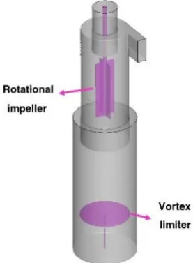
2. 1. Geometry The design of new cyclone is based on the idea that the vortex length and separation performance can be increased by decreasing friction losses in a cyclone. The new design differs from a classical cyclone with the separation space. It has inner and outer cylinders without a conical part, and a vortex limiter [30]. The idea of new design dynamic cyclones is rooted in the studies when in order to increase efficiency and decrease pressure drop a rotational separator is designed for the new design cyclone. The geometry used in dynamic new design cyclones as can be seen in Figure 1 is similar to that of new design static cyclone and the only difference is the rotational impeller.
2. 2. Governing Equation For a non-compressible fluid continuum and momentum equations can be written as the following:
i
i
u 0 x
=
(1)
2 1
i i i
j ij
j i j j j
u u P u
u R
t x x x x x
+ =− + −
(2)
Where u̅i is average speed, xi is the location, P̅ is the average pressure, 𝜌 is the constant density of gas, ν is kinetic viscosity and Rij= ú̅lú̅j is Reynolds stress tensor. Here, úi= ui− u̅l is the ith fluctuating velocity component.
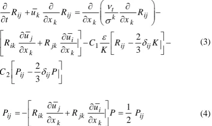
The RSTM provides differential transport equations for evaluation of the turbulence stress components where the turbulence production terms are defined as follows:
1 2 2 3 2 3 t
ij k ij k ij
k k k
j i
ik jk ij ij
k k
ij ij
R u R R
t x x x
u u
R R C R K
x x K
C P P
+ = − + − − − − (3) 1 2 j i
ij ik jk ij
k k
u u
P R R P P
x x
= − + =
(4)
With P being the fluctuating kinetic energy production.
νtis the turbulent (eddy) viscosity; and 𝜎𝑘= 1, 𝐶1=
1.8, 𝐶2= 0.6 are empirical constants [35].
The transport equation for the turbulence dissipation rate, 𝜀, is given as follows:
2
1 2
t j
j j j
ij j u
t x x x
C R C
K x K
+ = + − − (5)
In Equation (5), 𝐾 =1
2𝑢 ′
𝑖𝑢𝑖′
̅̅̅̅̅̅̅ is the fluctuating kinetic
energy, and 𝜀 is the turbulence dissipation rate. The values of constants are σε= 1.3, 𝐶𝜀1= 1.44 𝑎𝑛𝑑 𝐶𝜀2=
1.92.
To solve the couple of velocity and pressure, SIMPLE algorithm is used. For this study in two-phase equations a one way coupling is used and Eulerian-Lagrangian model is used to model two-phase state. In this model continuous phase is assumed to be the gas and discreet phase is particles. Discrete equations are numerically solved for the particles using Rang-Kutta method. To calculate the path of particles in the fluid, discrete phase model (DPM) is used to track particles individually. Equation of motion for small particles includes non-linear effect of drag force and gravitational forces which is presented in following equation:
(
)
2 3 4 p i D P ii p i
du C Re
u u g
dt d S
= − + (6)
24
1
D P
P
C for Re
Re
= (7)
2 3
24 1
1 1 1 400
6
D P P
P
C Re for Re
Re = + (8) P j j P
u u d
Re
−
= (9)
where uip is particle’s velocity, xi is the location of the particle, d is the diameter of the particle, S is the ratio of particle density to flow density and gi is gravity acceleration. The right side of Equation (6) is the drag force due to relative slippage of particles and flow. Drag force, generally, is the impelling force and drag coefficient can be computed using Equations (7) and (8) and ReP is Reynolds number of the particles which is calculated using Equation (9). Impact of the particles to the walls of the cyclone is treated with elastic coefficient of 0.8 and it is assumed that impact between particles is negligible.
2. 2. Grid Generation Grid generation of the new design dynamic cyclone is depicted in Figure 2. This type of cyclone has 2 to 2.5 million number of grids. In order to be sure that results are independent from grids, eight different gridding systems are used. Figure 3 shows the independence of pressure drop from gridding system.
2. 3. Validation To attain confidence about the simulations, it is necessary to compare the simulation results with the available data. As can be seen from
Figure 2. Deposition efficiency on a single square in channel
Figure 4, one can approve that numerical values are well correlated with experimental and analytical values. For validating the collection efficiency results, Table 1 compares the present numerical results and the related experimental data of Wang [36] for different PSDs in conventional cyclones. In Table 1, D50 is the diameter of
a particle which has 50% probability of separation and 50% probability of escaping and is a criterion for
comparing efficiency of cyclones. Physical
characteristics of A–E particles are shown in Table 1.
MMD and GSD are mass median diameter and geometric standard deviation, respectively. As shown in this table, a good agreement is observed between numerical predictions and experimental results.
3. RESULTS AND DISCUSSION
In this section, first the effect of variation in geometrical parameters on inlet velocity, pressure drop in the cyclone and turbulence inside new design dynamic cyclone is investigated. Then, comparing collection efficiency and pressure drop between static and dynamic new design cyclones with similar boundary conditions is followed.
Figure 4. Deposition efficiency on a single square in channel
TABLE 1. Strouhal number for different geometric cases
Dust
PSD D50
ρP MMD/GSD Experimental Numerical
A 1.77 20/2 2.74 2.41 B 1.82 21/1.9 3.75 3.32 C 1.87 23/1.8 3.60 3.151 D 1.52 19/1.4 - 7.1 E 2.37 13/1.7 4.40 4.07
Considered parameters include impeller diameter and number of blades, rotational speed of impeller, location of impeller, length of impeller and inlet speed.
3. 1. Effect of the Impeller Diameter Three different diameters of impeller are investigated. As can be seen from Figures 5 and 6,turbulence in new design dynamic cyclone with minimum impeller diameter is the lowest. With increase in impeller diameter, first turbulence is increased. More increase in impeller diameter leads to a decrease in kinetic energy. As can be observed, increasing impeller diameter results in a reduction in pressure drop. However, collection efficiency shows a maximum for the middle impeller diameter.
3. 2. Effect of the Number of Blades As shown in Figures 7 and 8, with increase in number of blades,
Figure 5. Effects of the impeller diameter on axial velocity, pressure distribution and turbulent kinetic energy contours
axial velocity increases in the outlet cylinder. With lower number of blades, kinetic energy of turbulence slightly decreases. However, with increase in number of blades in a new design dynamic cyclone, turbulence kinetic energy dramatically decreases. As shown decreasing number of blades from an optimum value will lead to a decrease in both collection efficiency and pressure drop. However, increasing number of blades results in more severe decrease in collection efficiency and pressure drop.
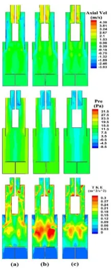
3. 3. Effect of the Impeller Rotational Speed This is a prominent parameter which was studied in three different levels. As can be observed from Figures 9 and 10, higher turbulence kinetic energy can be achieved with higher impeller rotational speed. The area of which low turbulence existed with low rotational speed,
Figure 7. Effects of the impeller rotational speed on axial velocity, pressure distribution and turbulent kinetic energy contours
Figure 8. Effects of the number of blades on pressure drop and collection efficiency
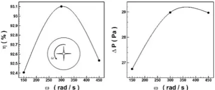
decrease dramatically with higher speeds. Moreover, turbulence increases in the lower cylinder. As depicted, pressure drop and collection efficiency have minimum and maximum points respectively. With increase in rotational speed, first pressure drop increases and then is constant. Furthermore, increasing rotational speed first leads to an increase in collection efficiency and then it efficiency reduces.
3. 4. Effect of the Location of Impeller To study the effect of the location of impeller it is located in three different locations. As illustrated in Figures 11 and 12, when the impeller installed at the maximum height, the
Figure 9. Effects of the impeller rotational speed on axial velocity, pressure distribution and turbulent kinetic energy contours
axial speed in output cylinder decreases, a low pressure zone occurs in the central line of the cyclone and turbulence energy increases in the lower cylinder. On the other hand, installing impeller at the lowest height increases axial velocity in output cylinder and low pressure zone emerges in the output cylinder and turbulence kinetic energy in the lower cylinder stands at its lowest state. As depicted, the highest collection efficiency coincides with highest level of impeller installation, and with lowering impeller it gradually decreases. This decrease is due to the fact that particles exit before entering the rotational field of the impeller. The highest pressure drop occurs when impeller is installed at the highest position, but with its descend, pressure drop decreases. When impeller gets down from the middle position, pressure drop increases.
3. 4. Effect of the Impeller Length To investigate the effect of impeller length, three different sizes of impeller were investigated. As can be observed from Figures 13 and 14, with increase in length of the impeller, axial velocity increases within the cyclone and turbulence energy is maximized. Moreover, as illustrated, increasing the length of the impeller leads to an increase in collection efficiency. For pressure drop, first it dramatically decreases with increasing length of impeller and then its decrease becomes slight and
Figure 11. Effects of the location of impeller on axial velocity, pressure distribution and turbulent kinetic energy contours
Figure 12. Effects of the location of impeller on pressure drop and collection efficiency
negligible. It can be implied that, for the new design dynamic impeller, increasing the length of the impeller is suitable for both efficiency and pressure drop.
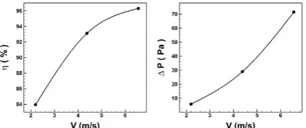
3. 5. Effect of the Inlet Velocity Different inlet velocities were studied and as can be observed from Figures 15 and 16 with increase in inlet velocity, axial velocity increases through entire cyclone and pressure variation increase within the cyclone. Furthermore, with increasing inlet velocity, first, efficiency increases in a high rate and then its rate of increase decreases. Nevertheless, pressure drop increases with inlet velocity.
Figure 14. Effects of the impeller length on pressure drop and collection efficiency
Figure 15. Effects of the inlet velocity on axial velocity, pressure distribution and turbulent kinetic energy contours
Figure 16. Effects of the inlet velocity on pressure drop and collection efficiency
3. 6. Comparison of Pressure Drop and Efficiency in Static New Design, Dynamic New Design and Conventional Static Cyclones As can be seen from Figure 17, the minimum pressure drop occurs in new design dynamic cyclones and maximum pressure drop occurs for static new design cyclones. High pressure drops are even severe for higher speeds in new design cyclones. Low values for pressure drop is an advantage of a good cyclone design and dynamic new design cyclone has achieved this. Figure 17 proves that in very low speeds the minimum efficiency for static new design cyclones and dynamic new design cyclone stands very close to the static cyclones at the top. With increasing speed, maximum efficiency belongs to the dynamic new design cyclones and static ones possess the lowest efficiency.
Figure 17. Comparison of collection efficiency and pressure drop for dynamic and static cyclones and static conventional cyclones
4. CONCLUSION
3. Small particles yield higher efficiency due to intensive rotation with higher speed with the impeller inside the cyclone.
4. Installing impeller at the lower positions leads to a decrease in efficiency.
5. With increase in impeller diameter, pressure drop in dynamic new design decreases.
6. With increase in impeller length, efficiency increases and pressure drop decreases.
7. Increasing inlet velocity results in increasing collection efficiency and increasing pressure drop.
8. Design of the dynamic new design cyclones can be manipulated for different flow regimes with the aim of maximum collection efficiency with change in rotational speed of impeller and re-location of the vortex limiter.
5. REFERENCES
1. McK, R., "Fundamentals of cyclone design and operation",
Procedings of . Australasian Institute of Mining and Metallurgy, Vol. 152, (1949), 203.
2. Stairmand, C.J., "The design and performance of cyclone separators", Transactions of the Institution of Chemical Engineers, Vol. 29, No., (1951), 356-383.
3. Elsayed, K. and Lacor, C., "The effect of cyclone inlet dimensions on the flow pattern and performance", Applied Mathematical Modelling, Vol. 35, No. 4, (2011), 1952-1968.
4. Cortes, C. and Gil, A., "Modeling the gas and particle flow inside cyclone separators", Progress in Energy and Combustion Science, Vol. 33, No. 5, (2007), 409-452.
5. Avci, A., Karagoz, I. and Surmen, A., "Development of a new method for evaluating vortex length in reversed flow cyclone separators", Powder Technology, Vol. 235, (2013), 460-466. 6. Zhao, B., Su, Y. and Zhang, J., "Simulation of gas flow pattern
and separation efficiency in cyclone with conventional single and spiral double inlet configuration", Chemical Engineering Research and Design, Vol. 84, No. 12, (2006), 1158-1165. 7. Qian, F. and Zhang, M., "Effects of the inlet section angle on the
flow field of a cyclone", Chemical Engineering & Technology: Industrial Chemistry‐Plant Equipment‐Process Engineering‐ Biotechnology, Vol. 30, No. 11, (2007), 1564-1570.
8. Qian, F. and Wu, Y., "Effects of the inlet section angle on the separation performance of a cyclone", Chemical Engineering Research and Design, Vol. 87, No. 12, (2009), 1567-1572. 9. Erdal, F.M. and Shirazi, S.A., "Effect of the inlet geometry on the
flow in a cylindrical cyclone separator", Vol. 128, No. 1, (2006), 62-69.
10. Zhao, B., Shen, H. and Kang, Y., "Development of a symmetrical spiral inlet to improve cyclone separator performance", Powder Technology, Vol. 145, No. 1, (2004), 47-50.
11. Xiang, R. and Lee, K., "Exploratory study on cyclones of modified designs", Particulate Science and Technology, Vol. 19, No. 4, (2001), 327-338.
12. Chuah, T., Gimbun, J. and Choong, T.S., "A cfd study of the effect of cone dimensions on sampling aerocyclones performance and hydrodynamics", Powder Technology, Vol. 162, No. 2, (2006), 126-132.
13. Xiang, R., Park, S. and Lee, K., "Effects of cone dimension on cyclone performance", Journal of Aerosol Science, Vol. 32, No. 4, (2001), 549-561.
14. Yoshida, H., Fukui, K., Yoshida, K. and Shinoda, E., "Particle separation by iinoya's type gas cyclone", Powder technology, Vol. 118, No. 1-2, (2001), 16-23.
15. Qian, F., Zhang, J. and Zhang, M., "Effects of the prolonged vertical tube on the separation performance of a cyclone",
Journal of Hazardous Materials, Vol. 136, No. 3, (2006), 822-829.
16. Kaya, F. and Karagoz, I., "Numerical investigation of performance characteristics of a cyclone prolonged with a dipleg", Chemical Engineering Journal, Vol. 151, No. 1-3, (2009), 39-45.
17. Yoshida, H., Kwan-Sik, Y., Fukui, K., Akiyama, S. and Taniguchi, S., "Effect of apex cone height on particle classification performance of a cyclone separator", Advanced Powder Technology, Vol. 14, No. 3, (2003), 263-278. 18. Kępa, A., "The effect of a counter-cone position on cyclone
performance", Separation Science and Technology, Vol. 47, No. 16, (2012), 2250-2255.
19. Xiang, R. and Lee, K., "Effects of exit tube diameter on the flow field in cyclones", Particulate Science and Technology, Vol. 26, No. 5, (2008), 467-481.
20. Chen, J. and Liu, X., "Simulation of a modified cyclone separator with a novel exhaust", Separation and Purification Technology, Vol. 73, No. 2, (2010), 100-105.
21. Kępa, A., "Division of outlet flow in a cyclone vortex finder—the cfd calculations", Separation and Purification Technology, Vol. 75, No. 2, (2010), 127-131.
22. Hoffmann, A., De Groot, M., Peng, W., Dries, H. and Kater, J., "Advantages and risks in increasing cyclone separator length",
AIChE Journal, Vol. 47, No. 11, (2001), 2452-2460.
23. Safikhani, H., Akhavan-Behabadi, M., Shams, M. and Rahimyan, M., "Numerical simulation of flow field in three types of standard cyclone separators", Advanced Powder Technology, Vol. 21, No. 4, (2010), 435-442.
24. Wang, J.-J., Wang, L.-Z. and Liu, C.-W., "Effect of a stick on the gas turbulence structure in a cyclone separator", Aerosol Science and Technology, Vol. 39, No. 8, (2005), 713-721.
25. Farahani, S.N., Tahmasbi, V., Safikhani, H. and Abbassi, A., "Effects of using ribs on flow pattern and performance of cyclone separators", Engineering Applications of Computational Fluid Mechanics, Vol. 5, No. 2, (2011), 180-187.
26. Su, Y. and Mao, Y., "Experimental study on the gas–solid suspension flow in a square cyclone separator", Chemical Engineering Journal, Vol. 121, No. 1, (2006), 51-58. 27. Safikhani, H., Shams, M. and Dashti, S., "Numerical simulation
of square cyclones in small sizes", Advanced Powder Technology, Vol. 22, No. 3, (2011), 359-365.
28. Su, Y., Zheng, A. and Zhao, B., "Numerical simulation of effect of inlet configuration on square cyclone separator performance",
Powder Technology, Vol. 210, No. 3, (2011), 293-303. 29. Kim, H.-T., Lee, K. and Kuhlman, M., "Exploratory design
modifications for enhancing cyclone performance", Journal of Aerosol Science, Vol. 32, No. 10, (2001), 1135-1146.
30. Karagoz, I., Avci, A., Surmen, A. and Sendogan, O., "Design and performance evaluation of a new cyclone separator", Journal of Aerosol Science, Vol. 59, (2013), 57-64.
31. Safikhani, H. and Mehrabian, P., "Numerical study of flow field in new cyclone separators", Advanced Powder Technology, Vol. 27, No. 2, (2016), 379-387.
32. Safikhani, H., "Modeling and multi-objective pareto optimization of new cyclone separators using cfd, anns and nsga ii algorithm",
33. Jiao, J., Zheng, Y., Wang, J. and Sun, G., "Experimental and numerical investigations of a dynamic cyclone with a rotary impeller", Chemical Engineering and Processing: Process Intensification, Vol. 47, No. 9-10, (2008), 1861-1866. 34. Jiao, J., Zheng, Y., Sun, G. and Wang, J., "Study of the separation
efficiency and the flow field of a dynamic cyclone", Separation and Purification Technology, Vol. 49, No. 2, (2006), 157-166.
35. Launder, B.E., Reece, G.J. and Rodi, W., "Progress in the development of a reynolds-stress turbulence closure", Journal of Fluid Mechanics, Vol. 68, No. 3, (1975), 537-566.
36. Wang, L., "Theoretical study of cyclone design", Texas A&M University, (2005),
Numerical Study of Flow Field in New Design Dynamic Cyclone Separators
H. Safikhani, F. Esmaeili,S. Salehfard
Department of Mechanical Engineering, Faculty of Engineering, Arak University, Arak, Iran
P A P E R I N F O
Paper history:
Received 04 September 2019
Received in revised form 16 October 2019 Accepted 08 November 2019
Keywords:
Dynamic Cyclone New Design Cyclone Collection Efficiency CFD
Discrete Random Walk
کچ ی هد
هلاقم نیا رد ، لدم نایرج یددع یزاس نولکیس رد لایس
یسدنه یاهرتماراپ ریثآت .تسا هدش ماجنا دیدج لسن یکیمانید یاه
.تسا هدش یسررب نولکیس یدرکلمع یاهرتماراپ رب هناورپ ینارود تعرس و لحم ،لوط ،رطق دننام فلتخم یسدنهریغ و
تلاداعم نیگنایم ریوان هدش یریگ
–
هدش لح نایرج رد سکوتسا رلیوا یزافود لدم و دنا
–
کی ژنارگلا هدش لیلحت زین ههار
یم ناشن جیاتن .تسا نولکیس رد هک دهد
نولکیس زا رتشیب یزاسادج هدزاب و رتمک راشف تفا دیدج لسن یکیمانید یاه یاه
یم یتنس .دشاب نینچمه ، نییاپ هاگیاج رد هناورپ بصن هک دیدرگ صخشم یم هدزاب رتشیب شیازفا ثعاب رت
.ددرگ
doi: 10.5829/ije.2020.32.02b.22