Journal of Computing and Security
Unified Byte Permutations for the Block Cipher 3D
Hamid Mala
a,∗
aDepartment of Information Technology Engineering, University of Isfahan, Isfahan, Iran
A R T I C L E I N F O.
Article history:
Received:15 December 2012
Revised:17 June 2013
Accepted:10 July 2013
Published Online:20 December 2013 Keywords:
Block Cipher 3D, Diffusion, Graph Theory, Order/Degree Problem, Permutation
A B S T R A C T
3D is a 512-bit block cipher whose design is inspired from the Advanced Encryption Standard (AES). Like the AES, each round of 3D is composed of 4 transformations including a round-key addition, a byte-wise substitution, a byte-wise shuffle and an MDS matrix multiplication. In 3D, two distinct byte-wise permutations are employed for odd and even rounds. In this paper, using concepts from graph theory, we design a unified byte permutation for both odd and even rounds with the same diffusion property as the original cipher. The main advantage of this new transformation is in hardware implementation of the cipher where with less resources we can speed up the encryption/decryption process.
c
2014 JComSec. All rights reserved.
1
Introduction
The Advanced Encryption Standard (AES)[1] is the most world-widely used block cipher in the current century. Since the selection of this 128-bit block cipher as the standard by NIST in 2001, its design rationale has inspired many cryptographic primitives including the LEX stream cipher [2], the ECHO hash function [3], the ALPHA-MAC message authentication code [4] and the 3D block cipher [5].
3D is an AES-based block cipher introduced by Nakahara at CANS 2008. This 22-round block ci-pher operates on bit blocks and supports 512-bit keys. While AES, as a 128-512-bit block cipher, has a 4×4 byte state, 3D regards the 512-bit internal state as a 4×4×4 cube of bytes. Both ciphers have substitution-permutation structure and are composed of 4 components in each round: XORing the inter-nal state by the round subkey, byte-wise substitution, byte permutation, and finally a column-wise linear diffusion obtained through multiplication of a 4×4 MDS (Maximum Distance Separable) matrix by all of the 4-byte columns of the state. Subkey mixing,
∗ Corresponding author.
Email address:[email protected](H. Mala) ISSN: 2322-4460 c2014 JComSec. All rights reserved.
and even rounds. So, when implementing this cipher in hardware, we have to either implement at least two rounds of the cipher or add an extra multiplexer to choose between these two transformations in odd and even rounds. The former solution requires more hard-ware area and the latter imposes more latency to the encryption/decryption process.
In this paper, we propose a unified byte permuta-tion for all rounds of 3D. The proposed permutapermuta-tion improves the implementation efficiency of the modi-fied 3D with the same effect on the diffusion of three rounds of the cipher as the original byte permutations. The method that we use to obtain this byte permuta-tion is based on concepts from graph theory. In fact, we model the diffusion of three rounds of 3D as prop-erties of a directed graph, and then present graphs satisfying these properties.
1.1 Related Work
The idea of using a graph-theoretic model for diffusion properties of a block cipher is studied by Massey in [8]. He combines a block shuffle, called Armenian shuffle, with a two-block linear transformation, called pseudo-hadamard transform (PHT), to compose the diffusion layer of the well-known SPN (Substitution Permutation Network) block cipher SAFER+. Later, at FSE 2010, by modeling the internal block shuffle of the type-II generalized Feistel structure as a graph, Suzuki et al. show that the diffusion of this block cipher structure can be improved by modifying the traditional cyclic shift of sub-blocks by some new shuffles [9]. The SHA-3 finalist JH uses a permutation
Pd over 2d words in its compression function [10]. In fact, the compression function of JH has an SPN structure which uses the permutationPdalong with a 2×2 MDS matrix as the diffusion layer. It is shown that this structure has an equivalent SPN structure in which distinct permutations are used alternately instead of the samePdin all rounds.
1.2 Paper Organization
The rest of this paper is organized as follows. Sec-tion2provides a brief description of 3D and reviews the required concepts of graph theory. Section 3is dedicated to the main contribution of this work. In Subsection3.1, we present a graph-theoretic model for a unified diffusion layer for 3D including an optimum byte shuffle which can be employed as an alternative for the 3D’s permutationsθ1andθ2. Then, a proce-dure to find graphs satisfying the required diffusion properties and several concrete examples for 64-byte permutations are introduced in Subsection3.2. The extension for 256-byte permutations is discussed in Subsection 3.3. The implementation benefits of the unified permutation on the 3D are discussed in Sec-tion4.
2
Preliminaries
In this section, we provide a brief description of the block cipher 3D, and briefly review the required back-ground from graph theory.
2.1 Brief Description of the Block Cipher 3D
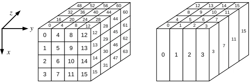
The block cipher 3D operates on 512-bit blocks under a 512-bit key, both represented as 4×4×4 states of bytes [5]. The state corresponding to a 64-byte data block A = (a0, a1, ..., a63) can be represented by a cube of 64 bytes, as shown in Figure1, or by a 4×16 matrixA, as shown in Table1.
Each square set of 16 bytes in Figure1is called a slice of the state. Since we can index each byte of the state by 16z+ 4y+x, 0 ≤x, y, z ≤3, each slice is described by fixing one of these three variables. For example, the slicez= 0 includes (a0, a1, ..., a15), and the slicex= 3 represents the lowest horizontal slice. According to Figure1, the four bytes 4i,4i+ 1,4i+ 2 and 4i+3 constitute the columncol(i). Conversely, the byte with indexj belongs to columncol(bj/4c). Each round of 3D applies the following four transformations to the state cube:
• Key Additionki: a bit-wise XOR operation be-tween the state cube and the subkey of the cur-rent round.
• Substitutionγ: this nonlinear operation consists of the byte-wise application of the AES S-box to the 64 bytes of the state cube.
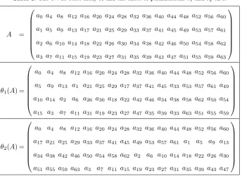
• Byte shufflesθ1andθ2: these two byte permu-tations are applied on the state cube in odd and even rounds, alternately. θ1 transfers the byte located in position (x, y, z) into location (x, y−x mod 4, z). In other words, it trans-forms the 4×16 state matrixAintoθ1(A) shown in Table1.
On the other hand, as shown in Table1,θ2 transfers the byte located in position (x, y, z) into location (x, y, z−x mod 4).
• Matrix multiplicationπ: the 4×4 MDS matrix of the Anubis cipher [11] is applied to each of the 16 columns of the state. Since the branch number of this matrix is 5 and the state is 3-dimensional, complete diffusion is achieved in three rounds [5].
Thei−thround of 3D can be represented by
τi(state) =π◦θ(i mod 2)+1◦γ◦ki−1(state), 1≤i≤22
In the complete cipher the round function is iterated 22 times, where in the last round the π function is replaced by the round key additionk22. The 64-byte state after the application of transformation T ∈ {ki, γ, θ1, θ2, π} in round 1 ≤ r ≤ 22 is denoted by
0
1
2
3 4
5
6
7 8
9
10
11 12
13
14
15
0 4 8 12 12
13
14
15 16 20 24 28
28
29
30
31 32 36 40 44
44
45
46
47 48 52 56 60
60
61
62
63
0 1 2 3
0 1 2 3
3
4 5 6 7
7 8 9 10 11
11 12 13 14 15
15
x
y
z
Figure 1. Byte numbering (left) and column numbering (right) for the 64-byte state array of 3D
indexiand the column with indexcin the stateXrT are denoted byXT
r(i) andXrT(col(c)), respectively.
2.2 Required Terminology of Graph Theory
Here we recall the required terminology of graph the-ory. A directed graph or digraphGis an ordered pair
G= (V, A), whereV is a non-empty set of distinct el-ements called vertices, andAis a set of ordered pairs (u, v), u, v ∈ V called arcs or edges. The order of a digraphGis the number of vertices inG, i.e.,|V|, and the size ofGis defined as the number of its arcs, i.e.,
|A|. The in-degree of a vertexv∈Gis the number of arcs of the form (ui, v), and its out-degree is defined as the number of arcs of the form (v, ui). A digraph in which the in-degree equals the out-degree (= ∆) for every vertex in the graph is called a diregular digraph of degree ∆. A sequence (vi1, vi2, ..., vil+1) of vertices
of the digraph Gis called a directed path of length
l inGif forj = 1,2, ..., l, (vij, vij+1) is an edge inG.
A digraphGis called connected if and only if for ev-ery ordered pair of vertices (vi, vj) inGthere exists a directed path fromvitovj. The distance between two verticesviandvjinGis denoted byδ(vi, vj) and defined as the length of the shortest directed path fromvitovj. The diameter of a digraphGis defined as max∀i,jδ(vi, vj).
3
New Byte Permutations for the 3D
Cipher
In this section, first we propose a graph-theoretic representation for the diffusion layer of 3D. Next, we try to find a unified byte shuffle to be used instead of
θ1 andθ2in every round.
3.1 Graph-Theoretic Model of the Diffusion Layer of 3D
In this section, we introduce a formal notion for the diffusion property of the 3D. What we mean, here, by
diffusion is the state where a byte in input affects all of the bytes in output. More formally, ifXrT00(j) can be
expressed by an equation containingXrT(i) for somei
andjandr≤r0, we sayXrT00(j) is affected byXrT(i).
Proposition 1. Diffusion properties of the four trans-formations of 3D are:
(a) Xk
r(i)is affected by onlyXr−1π (i).
(b) Xγ
r(i)is affected by onlyXrk(i).
(c) Xθ
r(i) is affected by only Xrγ(θ−1(i)) , θ ∈
{θ1, θ2}.
(d) Xπ
r(i) is affected by all of the four bytes of
Xθ
r(col(bi/4c)).
Proof. Since the transformationski andγ are
byte-wise and do not change the place of any bytes, prop-erties (a) and (b) are correct. The transformationθ
only changes the position of byteito the new position
θ(i), so (c) is correct. The fact that the branch num-ber of the MDS matrix of π is five guarantees that each of the four bytes ofXrθ(4i,4i+ 1,4i+ 2,4i+ 3) affects all of the four bytes ofXrπ(col(i)), so property (d) holds true.
If all of the output bytes of a cubic stateXT2
r2 are
af-fected byXT1
r1(i), we sayX
T1
r1(i) is diffused to all of the
bytes ofXT2
r2. For instance, as a result of Proposition1,
we can say thatXk
1(0) is diffused toX1π(col(0)). Using this concept, we come up with the following definition.
Definition 1. For the 3D, letDRibe the minimum number of rounds such that the byte with indexiof the first round input,X0(i), is diffused to all bytes of the state cube. Then, the maximum diffusion rounds for 3D, denoted byDRmax, is defined as DRmax =
max0≤i≤63DRi.
The following proposition is a more formal expo-sition of the designer’s statement saying “complete diffusion is achieved in three round”.
Proposition 2. For the 3D block cipherDRi= 3,0≤
i≤63, consequentlyDRmax= 3.
Proof. Considering Proposition 1, one can easily
Table 1. The 4×16 state arrayAand the effect of permutationsθ1andθ2 on it
A =
a0 a4 a8 a12 a16 a20 a24 a28 a32 a36 a40 a44 a48 a52 a56 a60
a1 a5 a9 a13 a17 a21 a25 a29 a33 a37 a41 a45 a49 a53 a57 a61
a2 a6 a10 a14 a18 a22 a26 a30 a34 a38 a42 a46 a50 a54 a58 a62
a3 a7 a11 a15 a19 a23 a27 a31 a35 a39 a43 a47 a51 a55 a59 a63
θ1(A) =
a0 a4 a8 a12 a16 a20 a24 a28 a32 a36 a40 a44 a48 a52 a56 a60
a5 a9 a13 a1 a21 a25 a29 a17 a37 a41 a45 a33 a53 a57 a61 a49
a10 a14 a2 a6 a26 a30 a18 a22 a42 a46 a34 a38 a58 a62 a50 a54
a15 a3 a7 a11 a31 a19 a23 a27 a47 a35 a39 a33 a63 a51 a55 a59
θ2(A) =
a0 a4 a8 a12 a16 a20 a24 a28 a32 a36 a40 a44 a48 a52 a56 a60
a17 a21 a25 a29 a33 a37 a41 a45 a49 a53 a57 a61 a1 a5 a9 a13
a34 a38 a42 a46 a50 a54 a58 a62 a2 a6 a10 a14 a18 a22 a26 a30
a51 a55 a59 a63 a3 a7 a11 a15 a19 a23 a27 a31 a35 a39 a43 a47
The 4 bytes of this column are carried over to four different columns of the same vertical slice after θ2, and then diffused to a complete vertical slice after the secondπ. These 16 bytes of this vertical slice are carried over to the 16 columns of the cube by the nextθ1permutation, and finally, after the thirdπall the 64 bytes are affected.
Our objective here is to find a byte shuffle such that by replacing it forθ1 andθ2 in 3D we get the same
DRmax= 3. To find such a shuffle, in general form, we have to search for a byte permutation of order 64, P∗ :{0,1, ...,63} → {0,1, ...,63}. Obviously, the cost of exhaustive search for this problem is too high; therefore, we present a graph-theoretic interpretation for the diffusion properties of a round of the cipher and then solve this problem.
Proposition 3. Suppose we replace the byte permuta-tions of 3D,θ1andθ2, by an arbitrary byte permutation
P :{0,1, ...,63} → {0,1, ...,63}. Since theπ
transfor-mation is a4×4MDS matrix, which propagates one
byte in input to 4 bytes in output, the minimum
possi-ble value forDRmaxis 3. Every byte permutation that
satisfiesDRmax= 3is called an optimum shuffle for
3D.
The following property for any optimum byte shuf-fle for 3D guides us to model the problem as a graph.
Proposition 4. Every optimum byte shuffle for the 3D structure permutes the 4 bytes of each column to four distinct columns.
Proof. Suppose this is not the case, i.e., there exists
an optimum permutationPthat permutes 4 bytes of a column to at most 3 distinct columns. Starting with a byte that diffuses to this specific column in the output of the first round, it will diffuse to at most 3 columns in the output of the second round; consequently, it will diffuse to at most 12 columns in the output of the 3rd round. This would contradict the fact thatP
is an optimum shuffle for 3D.
Consider a modified version of the 3D cipher where
θ1andθ2are replaced by an optimum shuffleP. Here, every byte inX0(i) diffuses to a 4-byte column in out-put of the first round. Now, based on Proposition4, we can introduce an equivalent graphical representation for the diffusion of this modified cipher.
Definition 2. Corresponding to an optimum byte shuffleP of 3D, we define a directed graph, denoted byG(P) with order 16. Each vertex of G(P) corre-sponds to one of the 16 columns of the state cube and is labeled with{0,1, ...,15}, compatible with the col-umn numbering of Figure 1. If the shuffleP carries one of the bytes ofcol(i) to one of the bytes ofcol(j), a directed arc is formed from nodeito nodej.
Based on Definition2and Proposition4, the fol-lowing property is deduced for the digraphG(P).
Corollary 1. For every vertex ofG(P)the in-degree and out-degree is 4.
The following theorem correlates the optimality of
Theorem 1. For every optimum shuffle of 3D, the corresponding digraphG(P), defined in Definition2, has diameter 2.
Proof. SinceP is optimum, each column in the
out-put of the first round must diffuse to all 64 bytes in the output of the next two rounds. This is equivalent to the statement that each node in G(P) must have a path of length 2 to each of the 16 vertices of this digraph.
So, to find optimum shuffles, we have to find diregu-lar digraphs of order 16, degree 4, and diameter 2. The following subsection gives an answer to this query.
3.2 A Procedure to Construct Optimum Per-mutations
In the context of graph theory, our problem is: “given order n = 16 and degree ∆ = 4, find a diregular digraph with the minimum diameter”. Such a prob-lem, in its general form, is of great interest due to its theoretical appeal and its possible applications in communication networks design. We, first, have to an-swer the question of existence of such a digraph. This is associated to the well-knownorder/degreeproblem in graph theory: Given natural numbersnand ∆ find the smallest possible diameter dn,∆in a digraph of ordernand maximum out-degree ∆ [12]. The follow-ing lower bound fordn,∆has been proved in [13].
dn,∆≥ dlog∆(n(∆−1) + ∆)e −1 (1) In our problemn= 16 and ∆ = 4, thus based on Equation1we have d16,4 ≥ dlog452e −1 = 2. This confirms Proposition2, i.e., the best possible value forDRmax is 3. In [14] Imase and Itoh proposed an algorithm to construct a nearly optimal diregular digraph of ordernand degree ∆ and diameterdlog∆ne. In our problem, this diameter isdlog∆ne=dlog416e= 2, which is of our interest. Customizing the algorithm of [14], we present a procedure to construct a diregular digraph with 16 nodes, diameter 2, and degree 4 as follows.
Algorithm 1 The procedure to construct a 4-diregular digraph of order 16 and diameter 2
Input: A set of 16 nodesV ={v0, v1, . . . , v15}
Output: A set of 64 directed arcsA={(vi, vj)}
1: ∆←4 % ∆ is the degree of the diregular digraph
2: n←16 %nis the order of the digraph
3: A←∅
4: fori= 0 ton−1do 5: forα= 0 to ∆−1do 6: j←∆×i+αmodn
7: A←A∪(vi, vj)
8: end for 9: end for 10: return A
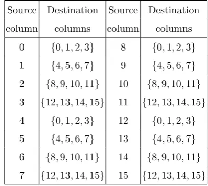
Table 2. Destination columns computed based on Algorithm1
for the 16 columns of the state cube
Source Destination Source Destination column columns column columns
0 {0,1,2,3} 8 {0,1,2,3}
1 {4,5,6,7} 9 {4,5,6,7}
2 {8,9,10,11} 10 {8,9,10,11}
3 {12,13,14,15} 11 {12,13,14,15}
4 {0,1,2,3} 12 {0,1,2,3}
5 {4,5,6,7} 13 {4,5,6,7}
6 {8,9,10,11} 14 {8,9,10,11}
7 {12,13,14,15} 15 {12,13,14,15}
As presented in Table2, the result of this procedure on the state cube is that an optimum permutation
P permutes the four bytes of column 0 to the four columns{0,1,2,3}, the four bytes of column 1 to the four columns{4,5,6,7}, ... and the four bytes of col-umn 15 to the four colcol-umns{12,13,14,15}. Note that four specific columns are assigned as the destination of four bytes of a specific column but the exact loca-tions in the destination columns are not forced by the procedure. On the other hand, the 16 bytes of slice
y=i, i= 0,1,2,3 are transposed to the 16 bytes of slicez=i, such that four bytes of each source column go to four bytes in four distinct columns. Hence, the first column of the source slice has 16×12×8×4 = 44×4! possible choices in the destination slice, the second column has 12×9×6×3 = 34×4! options, the third column has 8×6×4×2 = 24×4!, and, finally, the fourth column has 4! options. Thus, the total number of one slice to one slice transpositions is (4!)8. Since we have four one-slice-to-one-slice trans-positions, the total number of optimum permutations defined in the Algorithm1is ((4!)8)4= 2432≈1044. Recall that the number of all permutations over 64 bytes is 64!≈10250.
One can easily check that neither θ1 nor θ2 are optimum byte permutations. Based on the content of Table2, for example, 3 bytes out of the 4 bytes of column 0 are moved to three positions in columns 1, 2 and 3, while these columns do not have any path of length 1 back to column 0. This would suffice to conclude that this procedure does not introduce any involutory permutation. However, among the 2432 optimum permutations produced through the above procedure, here, we provide several concrete more easily imaginable samples:
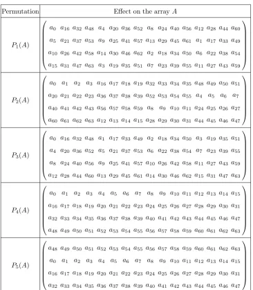
Table 3. Instances of the optimum permutations on the 4×16 state arrayA
Permutation Effect on the arrayA
P1(A)
a0 a16 a32 a48 a4 a20 a36 a52 a8 a24 a40 a56 a12 a28 a44 a60
a5 a21 a37 a53 a9 a25 a41 a57 a13 a29 a45 a61 a1 a17 a33 a49
a10 a26 a42 a58 a14 a30 a46 a62 a2 a18 a34 a50 a6 a22 a38 a54
a15 a31 a47 a63 a3 a19 a35 a51 a7 a23 a39 a55 a11 a27 a43 a59
P2(A)
a0 a1 a2 a3 a16 a17 a18 a19 a32 a33 a34 a35 a48 a49 a50 a51
a20 a21 a22 a23 a36 a37 a38 a39 a52 a53 a54 a55 a4 a5 a6 a7
a40 a41 a42 a43 a56 a57 a58 a59 a8 a9 a10 a11 a24 a25 a26 a27
a60 a61 a62 a63 a12 a13 a14 a15 a28 a29 a30 a31 a44 a45 a46 a47
P3(A)
a0 a16 a32 a48 a1 a17 a33 a49 a2 a18 a34 a50 a3 a19 a35 a51
a4 a20 a36 a52 a5 a21 a37 a53 a6 a22 a38 a54 a7 a23 a39 a55
a8 a24 a40 a56 a9 a25 a41 a57 a10 a26 a42 a58 a11 a27 a43 a59
a12 a28 a44 a60 a13 a29 a45 a61 a14 a30 a46 a62 a15 a31 a47 a63
P4(A)
a0 a1 a2 a3 a4 a5 a6 a7 a8 a9 a10 a11 a12 a13 a14 a15
a16 a17 a18 a19 a20 a21 a22 a23 a24 a25 a26 a27 a28 a29 a30 a31
a32 a33 a34 a35 a36 a37 a38 a39 a40 a41 a42 a43 a44 a45 a46 a47
a48 a49 a50 a51 a52 a53 a54 a55 a56 a57 a58 a59 a60 a61 a62 a63
P5(A)
a48 a49 a50 a51 a52 a53 a54 a55 a56 a57 a58 a59 a60 a61 a62 a63
a0 a1 a2 a3 a4 a5 a6 a7 a8 a9 a10 a11 a12 a13 a14 a15
a16 a17 a18 a19 a20 a21 a22 a23 a24 a25 a26 a27 a28 a29 a30 a31
a32 a33 a34 a35 a36 a37 a38 a39 a40 a41 a42 a43 a44 a45 a46 a47
position (x, z−x mod 4, y). The effect ofP1on the 4×16 state arrayAhas been demonstrated byP1(A) in Table3.
(2) P2: first applies transformation θ2 and then transposes the vertical slicesy= 0,1,2,3. In this manner, the byte located in position (x, y, z) is carried over to the position (z−x mod 4, y, x). The effect of this permutation on the 4×16 state arrayAhas been shown byP2(A) in Table3. (3) P3: first transposes the horizontal slices and then
transposes the vertical slicesz= 0,1,2,3, i.e., the byte located in position (x, y, z) is carried over to the position (z, x, y). The effect of this permutation on the 4×16 state arrayA has been demonstrated byP3(A) in Table3. (4) P4: first transposes the horizontal slices and then
transposes the vertical slices y = 0,1,2,3, i.e., the byte located in position (x, y, z) is carried
over to the position (y, z, x). The effect of this permutation on the 4×16 state array A has been shown byP4(A) in Table3.
The above mentioned permutations have fixed points, that is, for each of them there is at least one byte not permuted by the mentionedP1, P2, P3and
P4. For instance, (0,0,0) is a fixed point for all the four permutations given above. However this is not the case for all possible optimum permutations. An optimum permutation,P5, without any fixed point is proposed below. P5 moves the byte in position (x, y, z) to the position (z, x, y+ 1 mod 4). The ef-fect of this permutation on the 4×16 state arrayA
has been demonstrated byP5(A) in Table3.
3.3 Extending for a Higher Dimension
step in extending the AES may be for example a 2048-bit block cipher whose state is a 4×4×4×4 array of bytes. This 4-dimensional array can be represented as a hypercube, or equivalently four 4×4×4 cubes. To give a concrete permutation, let us indicate four cubes of a state byw= 0,1,2,3 and follow the same indexing based on (x, y, z) in each cube as for the state of 3D in Figure 1. The cube with indicator w = 0 includes columns indexing from 0 to 15, the cube with indexw= 1 includes columns from 16 to 31, the cube with indexw= 2 includes columns from 32 to 47, and the cube with indexw= 3 includes columns from 48 to 63. In this manner, the byte located in position (x, y, z, w), 0 ≤x, y, z, w ≤3 in the hypercube can be indexed by 64w+ 16z+ 4y+x. Let us consider a 2048-bit block cipher that uses four transformations in each round. First, as the round key addition, a 2048-bit round key is XORed to the state. Next, the same 8-bit S-box is applied to all 256 bytes of the state. Then a 256-byte permutation is applied, and finally, the same 4×4 MDS matrix is multiplied to each one of the 64 columns of the state.
Using the proposed method to model the diffusion property of an optimum permutation and the MDS matrix, we can show that, here each byte of the state affects all the 256 bytes of the state after 4 rounds. In our graphical model, we have to look for a diregular digraph of ordern= 64, diameter 3, and still degree 4. Based on the order/degree problem, the lower bound for the diameter of a diregular graph of ordern= 64 and ∆ = 4 isdlog∆(n(∆−1) + ∆)e −1 = 3. Moreover, the procedure of Subsection3.2, when customized for
n = 64 and ∆ = 4, would determine such an opti-mum permutation over 64 columns. The outcome of this procedure is that, in an optimum 256-byte per-mutation, the 4 bytes of columni, i= 0,1, ...,63 are displaced to 4 distinct bytes of columns 4i mod 64, 4i+ 1 mod 64, 4i+ 2 mod 64 and 4i+ 3 mod 64. The permutation carrying over the byte located in po-sition (x, y, z, w) into the position (w, x, y, z) follows the procedure of Subsection3.2, hence, an optimum permutation over 256 bytes. This transformation can be considered as three consecutive matrix transposi-tions: first transposing in the w−zplanes, then in
y−zplanes, and finally inx−y planes.
4
Concluding Remarks
In this paper, we proposed a graph-theoretic model for the diffusion property of the AES-based block cipher 3D. Like AES, the diffusion layer of 3D is composed of two transformations: a byte shuffle that permutes the 64 bytes of the state cube, and a 4×4 MDS matrix that is multiplied to all 16 columns of the state cube. Each byte of the state affects all the 64 bytes after three rounds. However, this property
of 3D is achieved at the cost of using two distinct byte shuffles in odd and even rounds which in turn increases hardware implementation cost of the cipher. In this paper, assuming a unified byte shuffle for all rounds of the cipher, we modeled the diffusion property of 3 rounds as a diregular directed graph of order 16, diameter 2 and degree 4. Then we presented a procedure to obtain such a digraph, which proposes 2432optimum byte shuffles in the 4×4×4 cubic state. We believe that replacing the same byte permutation for every round of 3D, instead ofθ1andθ2, will improve hardware performance of the cipher.
The typical methods used in hardware implemen-tation of a block cipher includebasic iterated,partial
loop unrolling, andfull loop unrolling architectures,
each with the potential of several levels of pipelining [15]. The round iterated architecture is the best choice when there exist restrictions on the maximum area of a cryptographic module. For a block cipher like 3D with a big block size, the choice of round iterated is preferable. In this architecture, one round of the cipher is implemented as a combinational logic and supplemented with a single register and a multiplexer before the round. In the first clock cycle, input block of data is fed to the circuit through the multiplexer and stored in the register. In each of the subsequent clock cycles, by proceeding the data block through the circuit, one round of the cipher is evaluated, and then, the result is fed back to the circuit through the multiplexer, and stored in the register.
However, since odd and even rounds of 3D use two distinct shuffles, some adjustments in the basic iter-ated architecture are inevitable. We have two possi-bilities:
- we can iterate at least two rounds, or
References
[1] Joan Daemen and Vincent Rijmen. The Design of Rijndael: AES - The Advanced Encryption
Standard. Springer, 2002. ISBN
978-3-642-07646-6. doi: 10.1007/978-3-662-04722-4.
[2] Alex Biryukov. The Design of a Stream Cipher LEX. In Eli Biham and Amr M. Youssef, editors,
Selected Areas in Cryptography, volume 4356 of
Lecture Notes in Computer Science, pages 67–75.
Springer, 2006. ISBN 978-3-540-74461-0. [3] Ryad Benadjila, Olivier Billet, Henri Gilbert,
Gilles Macario-Rat, Thomas Peyrin, Matt Rob-shaw, and Yannick Seurin. SHA-3 Proposal: ECHO. Submission to NIST (updated), 2009. URLhttp://crypto.rd.francetelecom.com/ echo/doc/echo_description_1-5.pdf. [4] Joan Daemen and Vincent Rijmen. A New MAC
Construction ALRED and a Specific Instance ALPHA-MAC. In Henri Gilbert and Helena Handschuh, editors,FSE, volume 3557 ofLecture
Notes in Computer Science, pages 1–17. Springer,
2005. ISBN 3-540-26541-4.
[5] Jorge Nakahara Jr. 3D: A Three-Dimensional Block Cipher. In Matthew K. Franklin, Lucas Chi Kwong Hui, and Duncan S. Wong, editors,
CANS, volume 5339 ofLecture Notes in Computer
Science, pages 252–267. Springer, 2008. ISBN
978-3-540-89640-1.
[6] Jorge Nakahara Jr. New Impossible Differen-tial and Known-Key Distinguishers for the 3D Cipher. In Feng Bao and Jian Weng, editors, IS-PEC, volume 6672 ofLecture Notes in Computer
Science, pages 208–221. Springer, 2011. ISBN
978-3-642-21030-3.
[7] Takuma Koyama, Lei Wang, Yu Sasaki, Kazuo Sakiyama, and Kazuo Ohta. New Truncated Differential Cryptanalysis on 3D Block Cipher. In Mark Dermot Ryan, Ben Smyth, and Guilin Wang, editors, ISPEC, volume 7232 of
Lec-ture Notes in Computer Science, pages 109–125.
Springer, 2012. ISBN 978-3-642-29100-5. [8] James Massey. On the Optimality of SAFER+
Diffusion. InProceedings of the Second AES Can-didate Conference, National Institute of Standards
and Technology, 1999.
[9] Tomoyasu Suzaki and Kazuhiko Minematsu. Im-proving the Generalized Feistel. In Seokhie Hong and Tetsu Iwata, editors,FSE, volume 6147 of
Lecture Notes in Computer Science, pages 19–39.
Springer, 2010. ISBN 978-3-642-13857-7. [10] Hongjun Wu. The Hash Function JH.
Submission to NIST (round 3), January 2011. URL http://www3.ntu.edu.sg/home/ wuhj/research/jh/jh_round3.pdf.
[11] Paulo Barreto and Vincent Rijmen. The Anubis
block cipher. Submission to the NESSIE Project, 2000.
[12] Mirka Miller and Jozef Sir´aˇn. Moore graphs and beyond: a survey of the degree/diameter problem.
The Electronic Journal of Combinatorics, DS14:
1–61, 2005.
[13] W.G. Bridges and Sam Toueg. On the impossibil-ity of Directed Moore Graphs. Journal of
Com-binatorial theory, series B, 29(3):339–341, 1980.
[14] Makoto Imase and Masaki Itoh. Design to Mini-mize Diameter on Building-Block Network.IEEE
Trans. Computers, 30(6):439–442, 1981.
[15] Kris Gaj and Pawel Chodowiec. FPGA and ASIC Implementations of AES. In Cetin Kaya Koc, editor,Cryptographic Engineering, pages 235–294. Springer US, 2009. ISBN 978-0-387-71816-3. doi: 10.1007/978-0-387-71817-0 10.