125 * Corresponding author
Email address: [email protected]
Initial blank design of deep drawn orthotropic materials using inverse
finite element method
Hashem Zamanian1, Mehdi Bostan Shirin2 and Ahmad Assempour3* 1,2
Center of Excellence in Design, Robotics and Automation, Department of Mechanical Engineering, Sharif University of Technology , Tehran, Iran
3
Department of Mechanical Engineering, Sharif University of Technology, Tehran, Iran
Article info: Abstract
In this work, an inverse finite element formulation was modified for considering material anisotropy in obtaining blank shape and forming severity of deep drawn orthotropic parts. In this procedure, geometry of final part and thickness of initial blank sheet were known. After applying ideal forming formulations between material points of initial blank and final shape, an equation system was obtained in terms of unknown initial positions on the blank sheet. Initial positions of material points were obtained by solving this equation system. In this algorithm, the Hill's anisotropic plasticity and associated plastic flow rule were used. Strain distribution on the final part was obtained by comparing the initial blank and final part. The method was applied for the simulation of drawing an orthotropic blank to a rectangular cup. Accuracy of the presented method was evaluated by comparing the results with numerical forward method and experiment results.
Received: 06/05/2012 Accepted: 22/09/2013 Online: 03/03/2014
Keywords:
Initial blank design, Orthotropic materials,
Inverse finite element method.
1. Introduction
Since anisotropic sheet forming process has taken an important role in such industries as automobiles, airplanes and electric appliances, modeling and numerical simulation of anisotropic materials are a great challenge for research and engineering applications.
Anisotropic sheet forming depends on many parameters such as elastic and plastic properties of blank die geometry, sheet thickness, blank shape blank holder force and friction [1,2]. The
126
numerical trial and error with enormous time and cost. In recent years, some researchers have used deformation theory of plasticity to determine initial blank and strain distribution on the deformed shape. This method is known as one step finite element or inverse finite element method (IFEM) and is very quick; therefore, it can be applied for blank shape optimization. As a result, less material is consumed, progressive processes on final part such as trimming are eliminated and qualification of the drawn part is improved. There are two main approaches in inverse formulations: linear and nonlinear inverse finite element method.
Different researchers have worked on nonlinear method. Majlessi [3, 4] used the concept of minimizing potential energy to predict the initial blank of square and axi symmetric parts. However, this method cannot be applied without implementation of boundary conditions like friction and blank-h older force. Guo and Batoz [5-8] used principle of virtual work to develop a nonlinear IFEM. This method can be applied without implementation of boundary conditions. However, due to the nonlinearities coming from large deformation and material properties, this method is very sensitive to the initial guess and needs an efficient initial guess. Assempour et al. [9] developed a linear inverse finite element method, known as unfolding technique. Their formulation is based on principle of potential energy minimization and linear strain-displacement relation. Therefore, it ends in a system of linear equations which can be solved very quickly. This method is very efficient in obtaining the initial blank; however, due to the nature of linear formulation, strain values are less accurate than nonlinear formulation. In order to increase accuracy and applicability of unfolding technique, Bostanshirin et al. [10] developed multi-step unfolding method and introduced a new mapping technique for applying the unfolding technique in multi-step inverse FEM. Zamanian et al. [11] presented a developed inverse finite element method to design initial blank of deep drawn metal matrix composites.
Deep drawing of the orthotropic materials is being investigated by some researchers using
incremental and experimental approaches [12-18]. But, no inverse finite element method has been developed for design initial blank of orthotropic materials in deep drawing process. In this work, a developed inverse finite element method was presented to obtain strain and stress distribution in final shape and design initial blank of deep drawing process for orthotropic sheets. Accuracy of the present method was evaluated by comparison with the results of ABAQUS, experimental results and numerical methods.
2. Kinematics
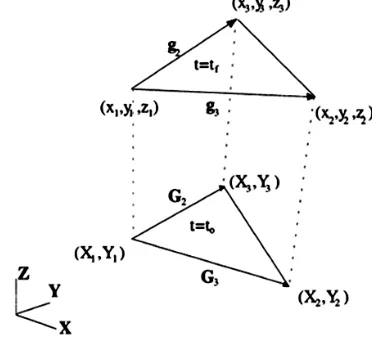
Geometry of final shape is discretized by linear triangular membrane elements. Then, elements are mapped to the horizontal plane and regarded as an initial guess. As shown in Fig. 1, this method considers the beginning and final shape of deep drawing process.
Components of left Cauchy-Green deformation are obtained as Eq. 1; where
= ‖ ‖
. andℎ
are components of , in the element local coordinate of finial shape, respectively. By considering only the initial and final states of elements and calculating left Cauchy-Green deformation tensor [B], principal stretches are obtained as Eq. 2 [19]. The{ }
are eigenvectors of . Principal stretches are obtained as Eq. 3. Logarithmic strains can be obtained from Eq. 2 as Eq. 4. Here, is directional of the principal stretch with x axis of local coordinate.
1
( 1,2)2
niT B ni i
i
(1)
cos sin ) ln (ln cos ln sin ln sin ln cos ln 2 1 2 2 2 1 2 2 2 1 xy y x
(2)
3. Integrated constitute low for anisotropic materials
127 orthotropic axes are taken as the coordinate
axes (x, y, and z) and F, G, H, L, M, N are anisotropic parameters. According to the associated plastic flow rule (
ij ij
f
. .
) and considering proportional deformation, stress distribution for orthotropic materials is derived as Eq. 5.
Fig. 1. Triangular membrane elements of the initial and final shapes.
ij ij
f
. .
(3)
2
=
+
= 1
A=
(
−
) + (
−
) + (
−
)
B=
2
+ 2
+ 2
(4)
where
D
is:
x x
e f
y y
e f
x y x y
D
(5)
HF GH FG A
n A H G H
H H F
A D
2 0 0
0 0 2
(6)
As shown in Fig. 2, for a tensile specimen cut at an angle θ to the x direction r-value can be expressed as Eq.7.
The anisotropy of the materials is represented by the strain ratio known as r-value where r is the Lankford value.
= + +
= (2 − − − 4 )
(7)
Therefore, each r-value can be obtained in terms of Hill’s anisotropic parameters as Eq.8.
Fig. 2. Tensile specimen cut at an angle θ to the x direction.
=
=
=
2 −
−
2( + )
(8)
128 =
( + 1)
= 1 + 1
= + 1
=( + )(2 + 1) 2 ( + 1)
(9)
The effective stress calculated from flow stress formulation and the effective strain corresponding to Eq. 4 can be obtained. The effective strain is expressed in Appendix.
4. Contact and friction modeling
The principle of virtual work is applied to the final work piece as Eq.10.
W
eintandW
e ext are
element internal and external works respectively. Element internal work
W
eint canbe written as Eq.11.
e e ext ee
W
W
int0
(10)
F
U
W n e
e
int *
int (11)
With * * * * j 1,2,3 W
V U
Un j j j which
are virtual displacements and are given by [8] as Eq.12.
F inte
i
T T B T i A hi (12)
are the Cauchy stresses and
B
is the strain operator in the local coordinate system of each element.
T
is transformation matrix between global and local coordinate systems.
F
eint isthe element internal force vector, A is the element area and h is thickness of the element. External work We
ext can be written as Eq.13.
F
eext is the element external force vector dueto the friction and tool actions.
F
U
W
eext
*n ext(13)
For more details refer to Ref [9]. Substituting Eq. 11 and 13 in Eq.10, Eq. 14 is derived and the Newton-Raphson method has been implemented for solving the set of nonlinear EQ. 14.
in t e x t
0
F
F
(14)5. Results and discussion
In order to compare the results of present method with the experimental one and numerical forward method, the tool geometry and material properties of a rectangular cup drawing benchmark mentioned by Choi [18] is adopted for the analysis. The simulation procedure is conducted as follows: Firstly, ABAQUS explicit has been used to form an orthotropic sheet with given dimensions to the rectangular cup. Secondly, the final shape of the work piece obtained with ABAQUS has been used as the analysis object in the present inverse approach.
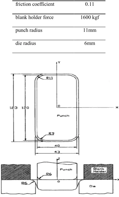
The material properties of the blank are given in table 1. The die geometry, friction coefficient and blank holder force are given in table 2.
The schematic view of deep drawing process of a rectangular cup is shown in Fig. 3. The rectangular cup is drawn to the depth of 30mm from a rectangular blank. The blank size is
130mm170mmwith the thickness of
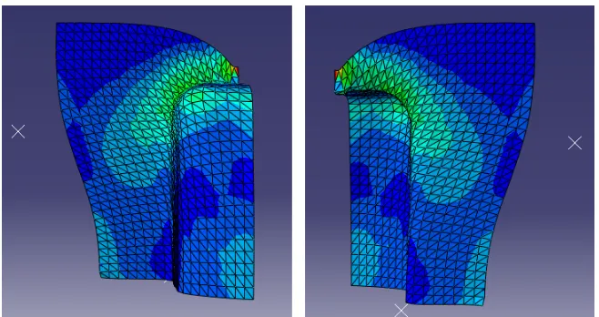
129 The calculation completes the simulation at the
stroke of 30mmand the final shape is shown in Fig. 5. The obtained shape is used as the input part for the proposed inverse method. Figure 6 illustrates the mesh of final shape with the flange profile for the rectangular cup example used in inverse finite element method.
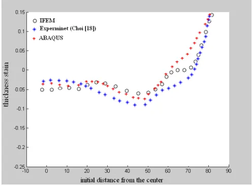
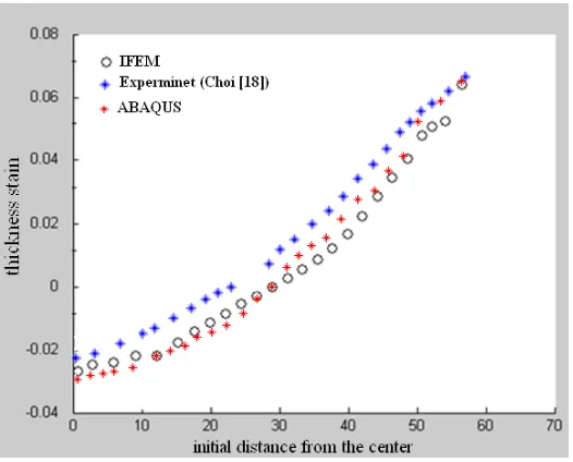
After inverse analysis of the part, the blank shape and strain distribution in the part are calculated. The initial blank obtained from developed inverse finite element method is shown in Fig. 8 and compared with the blank dimensions used in experiment and ABAQUS. As shown in Fig. 7, the initial blank obtained from developed inverse finite element method is nearly the Choi’s initial blank [18]. The maximum error is about 3.5% of real blank. Figure 8 compares the thickness strain distribution along the longer side of the rectangular cup, predicted by the inverse finite element method (IFEM) with the ABAQUS and experimental results. As shown in Fig. 8, results of the presented inverse finite element method are near the ABAQUS results except in wall region of the cup. The main sources of the errors are neglecting bending effects and using deformation theory of plasticity. However, errors between inverse and ABAQUS results with the experiment are a little high but the trend of them is in good agreement.
Figure 8 compares the thickness strain distribution along the longer side of the rectangular cup, predicted by the inverse finite element method (IFEM) with the ABAQUS and experimental results. As shown in Fig. 8, results of the presented inverse finite element method are near the ABAQUS results except in wall region of the cup. The main sources of the errors are neglecting bending effects and using deformation theory of plasticity. However, errors between inverse and ABAQUS results with the experiment are a little high but the trend of them is in good agreement.
Figure 9 compares the thickness strain distribution along the shorter side of the
rectangular cup, predicted by the inverse finite element method (IFEM) with the ABAQUS and experimental results. Again, results of the presented inverse finite element method are near the ABAQUS results. Although the trend of the results of all approaches are in good agreement, but there is a little difference between experiment and them.
Table 1. The material properties of the blank.
0
r r45 r90 K
(kgf/mm2)
n
01.833 1.434 2.016 58.78 0.274 0.0009
Table 2. Die geometry, friction coefficient and BHF.
0.11 friction coefficient
1600 kgf blank holder force
11mm punch radius
6mm die radius
130
Fig. 4. ABAQUS model and mesh system for a quarter of rectangular cup.
131
Fig. 6. Mesh system of the final shape with the flange profile.
Fig. 7. Quarter of initial blank shape obtained from IFEM method compared with ABAQUS and experiment.
Fig. 8. Comparison of thickness strain distribution along the longer side.
0
2 4
6 8 10 x 104 -2
0 2 4 6
x 104 0 0.5 1 1.5 2 2.5 3
132
Fig. 9. Comparison of thickness strain distribution along the shorter side.
6. Conclusion
Inverse finite element formulation has been modified for consideration of material anisotropy in obtaining the blank shape and forming severity of the deep drawn orthotropic parts. In this procedure, the geometry of final part and thickness of initial blank sheet are known. After applying ideal forming formulations between material points of initial blank and final shape, an equation system is obtained in term of unknown initial positions on the blank sheet. The initial positions of material points are obtained by solving this equation system. In this algorithm the Hill’s anisotropic plasticity and associated plastic flow rule have been used. The strain distribution on final part is obtained by comparing the initial blank and final part. The method has been applied for simulation of drawing an orthotropic blank to a rectangular cup. The accuracy of the presented method has been evaluated by numerical forward method (ABAQUS) and experiment results. The obtained blank dimensions and strain distribution are in good agreement with ABAQUS and experiment results. The existing
errors can be reduced by considering bending effects in the formulations and more accurate material behavior model. However the proposed method can be used as a fast tool, to predict the blank shape and strain distribution in preliminary design stage. Since the blank shape helps for optimization of deep drawing process, so initial blank designing is the best advantage of inverse method. Better convergence and lower computation time are other advantages of inverse finite element method. This work shows that, classic inverse finite element method can be developed for design and optimization of deep drawing process of anisotropic materials by using efficient yield function.
References
[1]
Jb. Catanach, G. Cuff and Fn. Cogswell, “The Processing of Thermoplastics Containing High Loading of Land and Continuous Reinforcing Fibers”, J. Polym. Engng. , Vol. 6, pp. 345-61, (1986).133 Nonferrous Met. Soc., Vol. 17, pp. 41-45,
(2007).
[3]
S. A. Majlessi and D. Lee, “Deep Drawing of Square-Shaped, Sheet Metal Parts Part1. Fem”, Transaction of ASME, Vol. 115, pp. 102-9, (1993).[4]
S. A Majlessi and D. Lee, “Development of Multistage Sheet Metal Forming Analysis Method”, J. Mat. Shaping Tech., Vol. 6, pp. 41-54, (1998).[5]
Y. Q. Guo, J. L. Batoz, J. M. Detraux and P. Duroux, “Finite Element Procedures for Strain Estimations of Sheet Metal Forming Parts”, Int. J. Numerical Methods in Engineering, Vol. 30, pp. 1385-401, (1990).[6]
J. L. Batoz, Y. Guo and F. Mercier, “The Inverse Approach with Simple Triangular Shell Elements for Large Strain Predictions of Sheet Metal Forming Parts”, Engineering Computations, Vol. 15, pp. 864-892, (1998).[7]
Y. Guo and Jl. Batoz, “Recent Developments on the Analysis and Optimum Design of Sheet Metal Forming Parts Using a Simplified Inverse Approach”, Computers and Structures, Vol. 78, pp. 133-48, (2000).[8]
H. Naceur, A. Delaméziere, J.L. Batoz, Y.Q. Guo and C. Knopf-Lenoir, “Some Improvements on the Optimum Process Design In Deep Drawing Using The Inverse Approach”, J. Materials Processing Technology, Vol. 146, pp. 250-62, (2004).[9]
R. Azizi and A. Assempur, “Application of Linear Inverse Finite Element Method In Prediction Of The Optimum Blank In Sheet Metal Forming”, J. Materials And Design, Vol. 29, pp. 1965-72, (2008).[10]
M. Bostan shirin and A. Assempour,“Development of A Multistep Inverse Finite Element Method Based On Unfolding Technique”, 20th Annual International Conference on Mechanical Engineering-ISME2012, (2012).
[11]
H. Zamanian, M. Kankarani Farahani, and A. Assempour, “Initial Blank Design of Deep Drawn Metal Matrix CompositesUsing Invers Finite Element Method”, 20th Annual International Conference on Mechanical Engineering-ISME2012, (2012).
[12]
Y. Q. Liu, J. C. Wang and P. Hu, “The Numerical Analysis Of Anisotropic Sheet Metals In Deep Drawing Processes”, J. Material Processing Technology, Vol. 120 , pp. 45-52, (2002).[13] A. M. Zaki, A. B. Nassr and M. G. El-Sebaie, “Optimum Blank Shape of Cylindrical Cups in Deep Drawing of Anisotropic Sheet Metals”, J. Material Processing Technology, Vol. 76, pp. 203-211, (1998).
[14] J. P. Correia and G. Ferron, “Wrinkling of Anisotropic Metal Sheets Under Deep-Drawing:Analytical and Numerical Study”, J. Material Processing Technology, Vol. 155 , pp. 1604-1610, (2004).
[15] S. Thuilllier, P. Y. Manach, L. F. Menezes and M. C. Oliveira, “Experimental and Numerical Study of Reverse Re-Drawing of Anisotropic Sheet Metals”, J. Material Processing Technology, Vol. 125, pp. 764-771, (2002).
[16] L. Duchene and A. M. Habraken, “Analysis of the Sensitivity of Fem Predictions to Numerical Parameters in Deep Drawing Simulations”, European Journal of Mechanics A/Solids, Vol. 24 , pp. 614-629, (2005).
[17] I. Salehinia and A. R. Shahani, “Effect of Sheet Anisotropy on the Wear in Deep-Drawing Process of a Cylindrical Cup”, International Journal of Mechanical Sciences, Vol. 51, pp. 856-868, (2009). [18] T. H. Choi, C. H. Lee and H. Huh, “Sheet
Metal Forming Analysis of Planar Anisotropic Materials with A Proper Numerical Scheme for the Blank Holding Force”, J. Metals and Materials, Vol. 3, pp. 408-419, (1998).
134
Appendix
1- Cauchy-Green deformation tensor [B]:
)
(
)
(
2
1
)
(
)
(
)
(
1
3 2 3 2 1 3 2 3 2 2 2 3 3 3 2 1 3 2 3 2 2 2 2 3 3 2 1 3 2 3 2 2 2 2 3 3 2 3 2 2 12 22 11h
h
h
h
L
L
L
L
h
h
L
h
h
h
h
L
L
L
L
h
L
h
h
h
L
L
L
L
h
L
h
h
h
h
h
B
B
B
y x x y y x y x x x x x y y y y y x x y2- Principal stretches:
B B B B B B B B B B B B B B 22 2 1 12 12 11 2 1 1 2 12 22 11 2 1 22 11 2 1 2 12 22 112 12 22 11 2 1 tan 1 tan 4 2 2 1 2 1 2 4 2 1 2 1 1
3- Effective strain: