Experimental Study of Synchronous Servo
Systems in Electrical and Electronic Engineering
Education
Yasar Birbir
Email: [email protected]
Ahmet Serhat Camlica
Karaman, Turkey, 70400 Email: [email protected]
Abstract—In this study firstly synchronous servo system design, function and application of this system are described. Voltage and phase relationships in this 3-line system are investigated. It is made clear why the synchronous servo system is adjusted under certain conditions and what influences play a role. Later we address the torque servo. A “synchronous servo” is defined. The effect of electrical feedback on synchronous is demonstrated and the measures needed for problem-free operation are explained.
Index Terms—synchronous servo, torque servo, permanent magnet synchronous generators
I. INTRODUCTION
Our torque synchro has a two pole armature which is brought out via slip rings. It can be connected UT =50Vrms to a transformer voltage (earth-free). When tranformer voltage switch is off, a direct voltage can be applied to the armature (U<50V). There are three coils S1 to S3 on the stator. These coils are displaced by 120o with each other and brought out the sockets S1 to S3 (all earth-free). The star point will not be accesseble from outside. End the experimental study of Synchronous-Servo System will be realized by means of two synchro-servo motors as seen in Fig. 1. After assembling synchro-servo system operetion modes will be set up [1].
The relationships between phase voltages and fluxes wil be invetigated in a two pole, three-line simple structre machine. Completion of this study, the students will be able to understansd the fundmental difference between synchronous machine operation and torque-synchro operation [2].
Manuscript received February 21, 2016; revised September 15, 2016.
II. SYNCHRONOUS SERVO APPLICATION
In this study coil positions will be determined by measuring zero-voltage method. It is necessary to feed excitation voltages of two servsos. Our synchronous servo is set up like a two-pole synchronous machine. It consists of:
A two pole rotor which is connected via slip rings;
A stator with coils which are arranged at 120° angles.
If the stator is connected to a 3-phase current supply via a matching transformer and the rotor is connected to a suitable DC supply, this machine operates like a synchronous motor. However, that is not the intended operational mode of the synchronous servo: The rotor is operated via a 50Hz AC supply instead of a DC supply [3].
Depending on the geometric position of the rotor with respect to that of the stator, voltages corresponding to the 3-phase linkage are generated in the individual coils. The instantaneous values of these voltages change with the main frequency [4].
If the rotor is in the position depicted in Fig. 2, the entire excited flux permeates coil U (S1), and the maximum transmitted voltage Umax is generated there. The flux is further divided among both the coils V (S2) and W (S3), where it generates voltages of equal magnitude Umax/2, provided the position of the rotor is maintained exactly. This condition prevails at times t0 and t1 (see Fig. 3). It applies to the other coils at time intervals displaced by 60° respectively.
For t0 respectively t1,
Uu = Umax
Uv = Umax/2 = Uw → Uvw = 0 and for Uuv = Uuw = Umax + Umax/2 =1.5 Umax
Technology Faculty, Marmara University, Istanbul, Turkey, 34722
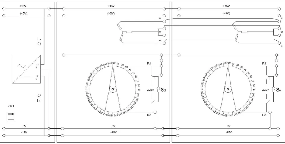
Figure 1. Synchronous servo system experimental setup.
Figure 2. Three phase Synchronous machine
On the basis of these designations, the angular position of the coils of the integrated servo can be determined [5]. For such measurements, it is always advantageous to use zero crossings: Uvw = 0 (Us2s3) instead of maxima, as the former can be read more accurately. When making these measurements it is particularly important to ensure that the rotors are excited at the same phase angle. If both servos are coupled with the coils S1-S1’; S2-S2’; S3-S3’, and the phase angles ØR1R2 = Ø’R1R2 are equal, the servo system can be operated with single excitation (Switch S1 on).
If the stator is connected to the 3-phase main supply via a matching transformer, and the rotor excited with a direct current, the machine operates like a synchronous motor [6]. However, this is not the intended mode of operation for a synchronous servo in Fig. 4 servo operation: The rotor is excited with a 50Hz AC supply. In Fig. 3 if the rotor is positioned as in Fig. 2, the maximum
flux φmax travels through coil S1 and is divided into φmax/2 in coils S2 and S3. Correspondingly, the voltage at coil S1 is Umax, while the voltage at coils S2 and S3 is Umax/2.
Figure 3. Phase relationships of a three-phase system
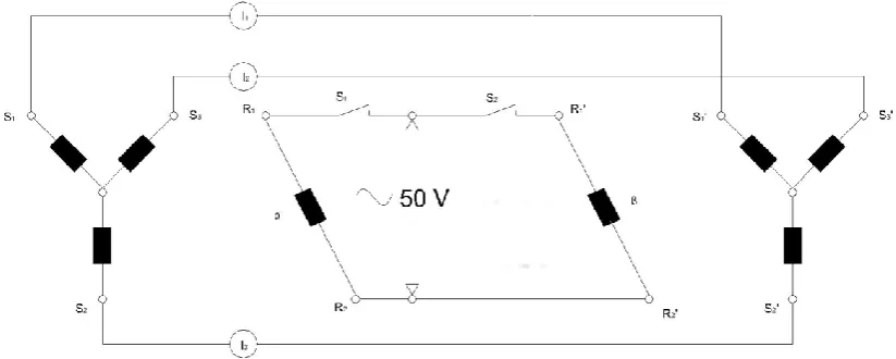
These voltages have a frequency of 50Hz. Fig. 4 shows the phase relationships at the terminals of a synchronous generator, or how they are supplied from a 3-phase main to a synchronous motor. The 3-phase current linkage is applied.
Figure 4. Three phase synchronous servo system.
III. RELUCTANCE EFFECT OF THE TWO-POLE
ARMATURE
The armature 2 moves in the same manner as armature 1 purely as a result of the magnetic effect, and aligns itself into a position where the magnetic resistance is as low as possible without being excited itself (switch S2 = off). It does not matter whether rotor 2 is shifted by 180°. It is not polarized, and serves primarily as a (small) magnetic resistor. A little residual is present and its existence can be demonstrated if switches S1 and S2 are turned off and the instruments set to the measuring range:
I1 - I3 = 10 µA and rotor 2 is turned, for example. However, this residual effect does not play any role compared with the reluctance effect.
Excitation of both rotors: If the same rotors are not in the same position, rotor 2 (right-hand) assumes the same position as the left-hand rotor once the latter has been excited (Switch S1 = on). In this case, Imax, Imax/2 and intermediate values occur in accordance with Fig 3. If rotor 2 (right-hand) is also excited (switch S2 = on), all currents (I1 to I3) become I = 0 (Ʃ1 = 0) once both rotors have assumed the same position.
As a result, identical voltages Us1 = U’s1 etc. are induced in the coils S1-S’1 to S3-S’3, and the differences are ∆US1S1’= 0. If a transformer is incorrectly poled now (ø = 180°), the corresponding rotor will also realign itself by the same factor F = 180°. Due the double voltage in the case of dual excitation, error voltages and differential currents, i.e. the torques, are also doubled (with respect to single phase excitation) [8].
IV. RESULTS
Normally, the rotor of a synchronous servo is not put into motion; instead, only its angle relative to the stator is changed. The synchronous servo functions like a rotary transformer with three coils whose transformation ratio with respect to the rotor is changed by means of angular adjustment (flux alteration). Due to the fact that the geometrical set up is identical to that of a synchronous machine, the “3-phase current” linkage
applies (in Fig. 2). The linkage values (maximum values) pass through positive and negative extremes at a frequency of 50Hz. The linkage values here represent not the time values but the angular values between the rotor and the stator [9].
The star point is not accessible; therefore, the individual coil voltages US1 to US3 cannot be measured directly. If the rotor is positioned as shown in Fig. 2, the flux distribution gives rise to the coils, with the maximum voltage
Umax at coil S1 Umax/2 at coil S2 Umax/2 at coil S3
As US2 = US3 = Umax/2, the voltage difference will be US2 - US3 = 0.
Consequently, an error voltage measurement US3 = 0 helps determine when the rotor is aligned in the same direction as S1. The zero voltage measurement is more sensitive than the measurement of a flat maximum voltage. If the polarity of the excitation is reversed, the instantaneous polarity of all instantaneous values also changes.
US23 = 0 when α = 330° and α = 150°, position of the coils: S1 = 330°
S2 = 330° + 120° – 360° = 90° S3 = 330° - 120° = 210°
We should connect a servo motor to a multiple socket outlet with the main plug. Note that the second servo can be connected to the same outlet and that the polarity of the plug can be changed if necessary. A multimeter (measuring = 100V) should be connected to the coils S1 and S2. Activate the excitation of the servo with the switch S1 = on. Determine the angles at which US23 = 0. Realize the case then, what are the positions of coils S2 and S3. Assemble in accordance with Fig. 4, while S1 and S2 = off. The multimeter measuring range: 100 mA AC; α = 330°; β = 0°. Switch S1 on. Current values will be I1, I2, and I3. The result will be α = β = 0° slight fluctuations caused by overshoot. If α is changed, β follows it with an accuracy of approx. 3°.
If the master (α, left-hand servo) is now excited, and the pointer is at α = 0°, the voltage distribution as at t0 resp. t1 applies as shown in Fig 3, with Uu = Umax, Uv = Uw = Umax/2. This distribution gives rise to the current distribution in the slave (right-hand servo) as measured with the flux φ in coil S1 and φ/2 in coils S2 and S3.
The rotor of the slave aligns itself so that the resistance of the magnetic circuit in the slave decreases to the lowest possible level (see Fig. 1, right) to applied voltage distribution. The magnetic material of the rotor aligns itself with the strongest lines of force is called reluctance effect. This effect is further enhanced in that the magnetic circuit assumes the lowest possible magnetic resistance. This mode is not suitable for servo operation. Termination of the master with an equivalent resistor network results in the same currents as in I1 ≈ 50mA*, I2 ≈ 25mA*, I3 ≈ 25mA*
How can you tell that it is not the residual effect which causes the slave to follow the master? Turn switches S1 and S2 off. Select the measuring range M. R1 = M.R2 = M.R3 = 10µA and move the slave. What do you observe? Subsequently, select M. R1-3 = 100 mA again, before turning on switches S1 and S2.
If the slave is moved, only very low induced currents are generated in coil S1’, S2’, S3’. The remanence effect generated by the movements of the non- excited slave is negligible compared with the reluctance effect. Set α = 0°; β = 90° of the system.
Both pointers swing to the same value. The setting tolerance is better than 2°. Torque is about twice as high as in first step. The currents at all angle-settings (following transient response): I1 = I2= I3 = 0, ƩI = 0. The slave responds to rapid adjustments to the master reliably with overshooting [10].
The experimentel set up in Fig. 4 is called synchro systems. Such System is used for (long-distance) transmission of angles, torques and speed. It has been found this system proporties as fallows. Advantages: Simple, robust system; also comes in larger versions; suitable for the transmisssion of angles (measured values, pointer), transmission of torques for carrying out adjustments, and transmisison of speeds (full-circle opereation), practically maintenance-free (the service life of slip carbon brushes is much longer than that of collector carbon brushes)
Disadvantages: Elastic system, due to the armature mass and magnetic forces: tends to over shoot easily if the mass is large compared with the magnetic force; restricted torques and setting tolerances.
V. CONCLUSION
Synchronous servo motors require analog feedback control systems of some type. Typically, this involves a potentiometer to provide feedback about the rotor position, and some mix of circuitry to drive a current through the motor inversely proportional to the difference between the desired position and the current position. Closed loop control may be essential for high accelerations, particularly if they involve variable loads.
A control loop uses feedback from the motor to help the motor get to a desired state (position, velocity, and so on). There are many different types of control loops.
Generally, the PID (Proportional, Integral, and Derivative) control loop is used for servo motors. When using a control loop such as PID, you may need to tune the servo motor. Tuning is the process of making a motor respond in a desirable way. Tuning a motor can be a very difficult and tedious process, but is also an advantage in that it lets the user have more control over the behavior of the motor.
ACKNOWLEDGEMENT
This study has been produced from a Master thesis is named “Investigation of Servo Systems as Experimentally” submitted at Marmara University Institute of Pure and Applied Sciences. In addition, this study developed from a research project entitled “Reorginizing Electric Machinery and Circuits Laboratory” supported by Marmara University Scientific Research Projects Center of Science, Coordinator: Assoc. Prof. Dr. Yaşar BİRBİR and collages, Proje No: FEN-E-120514-0148. The authors give thanks to Marmara University BAPKO coordinator, Marmara University Institute of Pure and Applied Science, Technology Faculty Electric & Electronic Engineering Department managers and employees.
REFERENCES
[1] H. Hashimoto, H. Yamamoto, S. Yanagisawa, and F. Harashima, “Brushless servo motor control using variable structure approach,”IEEE Transactions on Industry Applications, vol. 24, pp. 160-170, 1988.
[2] S. Morimoto, M. Sanada, and Y. Takeda, “Wide- speed operation of interior permanent magnet synchronous motors with high-performance current regulator,”IEEE Trans. Ind. Appl., vol. 30, pp. 920-926, 1994.
[3] M. A. Rahman, “Advances in interior permanent magnet (IPM) motor drives,” in Proc. IEEE PES Inaugural Conference and Exposition in Africa, Durban, South Africa, 2005, pp. 372-377. [4] N. Selvaganesan and R. R. Saraswathy, “A simple fuzzy modeling
of permanent magnet synchronous generator,”Elektrika, vol. 11, pp. 38-43, 2009.
[5] D. Yu, Q. Hu, and F. Zhao, “Synchronous motion control of biaxial driving system with linear servo motors,” in Proc. IEEE International Conference on Automation and Logistics, 2009, pp. 638-641.
[6] R. Leidhold, “Position sensorless control of PM synchronous
moto ased on zero-sequenc a njection,” IEEE
Transactions on Industrial Electronics, vol. 58, pp. 5371-5379, 2011.
[7] H. Lu, “On the drive control strategy of permanent magnet linear synchronous motor, artificial intelligence,” in Proc. 2nd
International Conference on Management Science and Electronic Commerce, 2011, pp. 458-461.
[8] A. Duysak, A. Unsal, and J. L. Schiano, “Development of a laboratory module for intelligent and classical control classes,”Energy Educ. Sci. Tech-B, vol. 4, no. 3, pp. 1405-1416, 2012.
[9] M. Dogan and M. Dursun, “Application of speed control of permanent magnet synchronous machine with PID and fuzzy logic controller,”Energy Educ. Sci. Tech-A, vol. 28, no. 2, pp. 925-930, 2014.
[10] Y. Fen, M. Zhengfeng, W. Tao, Z. Tong, and X. Z. Zhan, “Research on control methods of permanent magnet synchoronous motor position servo system,” in Proc. International Conference on Advanced Mechatronic Systems, Beijing, China, 22-24 August, 2015, pp. 261-266.
Yasar Birbir received B.S degree from Gazi University, M.S and PhD. from Marmara University. He attended World Bank Industrial Training Project at Indiana and Purdue Universities from 1989 to 1990. He had worked as a visiting research scientist for fifteen months at Drexel University Electrical and Computer Engineering Department from 1992 to 1993. Currently he has been working as a Professor at Technology Faculty in department of Electrical Engineering. He teaches undergraduate and graduate courses in Power Electronics Courses and Electrical Machinery Drives. His current interests beside power electronic converters and drivers, electromagnetic filtering process in the industry and the application of electric currents and electric field effects for sterilization of different microorganisms. Yasar Birbir is an expert on inactivation of archaea and hide bacteria using different electric current applications in leather industry. He has published 20 research articles, presented 33 oral and poster presentations. He has graduated 12 master and two doctorate students and completed 8 scientific projects.
Ahmet Serhat Camlica graduated from the