Implementation of Output Capacitorless LDO
Regulator Based on Flipped Voltage Follower for
Low Power Applications
Min-Chin Lee, Chong-Lin Shu, and Xiao-Xuan Yang
Department of Electronic Engineering, Oriental Institute of Technology, New Taipei City, Taiwan Email: lmchin@mail.oit.edu.tw, {oitmsic2218, minking0525}@gmail.com
Abstract—This paper proposes a based flipped voltage follower Output Capacitorless Low-Dropout (OCL-LDO) regulator with voltage spike detection circuit for low power applications. The OCL-LDO regulator introducing a capacitive coupling circuit at the output of the LDO for output voltage spike detection. The detection circuit uses the transient voltage at the output of the LDO to instantaneously increase the charge and discharge current of the improved Flipped Voltage Follower (FVF). The power transistor gate switching rate can be improved to increase the transient response of the LDO. This based flipped voltage follower OCL-LDO regulator with voltage spike detection circuit is designed using TSMC 0.35μm 2P4M CMOS process technology. According to the simulation and measured results, the circuit with chip area is 1.35×1.35mm2,
total chip power dissipation about 0.92mW. Under heavy load condition this chip line regulation is 58mV/V and load regulation is 0.38mV/mA. The chip input supply voltage can operate from 1.6V to 3.3V, the load current from 5mA to 100mA and the output voltage can be stabilized at 1.0V.
Index Terms—Output Capacitorless Low-Dropout (OCL-LDO) regulator, Flipped Voltage Follower (FVF), load regulation, line regulation, Power Supply Rejection Ratio (PSRR)
I. INTRODUCTION
At present, the functions of portable electronic products are updated, and the application is diversified and can be used for a long time toward low power and small area. Therefore, a high-efficiency power management module and a mixed signal circuit are required to be integrated on the same system chip (SOC) to achieve a variety of low power applications. A low-dropout voltage (LDO) regulator, with low noise, small size, and improved performance, is the mainstream of low-power regulation and intelligent power management regulator circuits [1]. Traditional LDO linear regulators require an output filter capacitor of a few microfarads to a dozen microfarad grades as frequency compensation, thus accounting for PCB area and cost. Among all on-chip LDO regulator, the Flipped Voltage Follower (FVF) based LDO regulators are more attractive in terms of simplicity, fast transient responses and low-voltage power
Manuscript received January 7, 2019; revised May 10, 2019.
consumption [2]. Transient response is a critical dynamic specification in LDO regulator design. Both the amplitude of the voltage spike and the recovery time of the regulated output voltage affect its overall accuracy, which indirectly impacts the performance of the circuits supplied by the LDO. In fact, the transient response of a LDO is related to different design parameters such as the closed-loop stability, the loop bandwidth and the slew rate at the gate of the power transistor [3], [4].
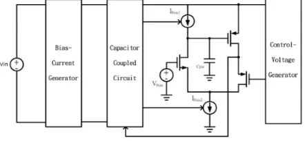
This paper proposes an FVF based output capacitorless (OCL-LDO) regulator architecture that utilizes capacitive coupling as an output voltage spike detection circuit without frequency capacitor compensation. It can be applied to System-on-Chip (SOC) low power applications, and the circuit architecture is shown in Fig. 1. The following is an analysis and design of the OCL-LDO core circuit, the voltage spike detection circuit, the bias current generating circuit and the control voltage generator which constitute the OCL-LDO regulator based on flipped voltage follower circuit.
Figure 1. Schematic of FVF based OCL-LDO regulator.
II. ARCHITECTURE AND CIRCUITS DESIGN
The schematic of the proposed OCL-LDO regulator with voltage spike detection circuit for low power applications is shown in Fig. 1. The core circuit of OCL-LDO regulator is basically based on the flipped voltage follower, which is a modified structure of the super source follower as shown in Fig. 2 [5]. VIN is the
unregulated input supply voltage of the LDO. MP is the power transistor, while
1 C
as follow: When power MOS
P
M (basic LDO) output current IO suddenly increases, due to the large
par C value (power MOS
P
M gate terminal parasitic capacitances), the LDO cannot immediately change the voltage
SG
V of
P
M to supply current, so this situation leads to a decrease in LDO output voltage
O
V . The source of the power MOS
1 C
M detects the drop of the LDO output voltage VO, and generates a falling error voltage at the gate of the power MOS MP to increase the current from the input power source
IN
V to the load, so that O
V rises to the basic principle of voltage regulation. Similarly, when
O I suddenly decreases, the LDO cannot immediately reduce the voltage
SG
V of MP and raises
O
V . Due to the performance of the negative feedback common-gate amplifier, the rising error voltage is generated at the gate of the power MOS MP to reduce the current from the input power source
IN
V to the load, so that VO is lowered to achieve the closed-loop regulated LDO output. As a result, the transconductances of MC1 and MC2 should be
large in order to improve the small-signal response.
Figure 2. OCL-LDO core circuit.
The OCL-LDO undergoes large-signal response when there is rapid and large change of output load current
O
I . When IO rapidly increases, the LDO cannot change VSG
of MPinstantaneously to provide current due to the large
par
C , and this situation causes to drop VO. The drop of
O
V reduces VSG of MC1, and it causes MC1 to cut-off
momentarily. Thus, IBIAS2IBIAS1is the discharging current
of par
C . The gate of the power PMOS MP drops rapidly to instantaneously increase the current from the input power source VIN to the load, so that the fast VO rises to
achive the basic principle of voltage regulation. Conversely, when IO suddenly decreases a lot, the LDO
cannot immediately reduce the VSG of MP and raises VO.
The sudden increase in VO causes the source voltage of
1 C
M to increase. Due to the performance of the common-gate amplifier, the drain of
1 C
M and the gate voltage of
2 C
M increase almost suddenly. This causes MC2 to be
cut-off immediately. Therefore, the charging current of
par
C is IBIAS1. The gate of the power PMOS MP rises
rapidly to instantaneously reduce the current from the input power source
IN
V to the load, so that the fast VO
drops to achives the voltage regulation performance. The following is the analysis and design of the output voltage spike detection circuit, the bias current generating circuit and the control voltage generator circuit which constitute the OCL-LDO regulator based on flipped voltage follower circuit.
A. Output Voltage Spike Detection Circuit
From the above analysis, both
1 BIAS
I and IBIAS2
determine slew rate of the closed loop of the OCL-LDO. Higher bias current does enhance the transient response of the LDO, but this approach consumes unnecessary power dissipation. The OCL-LDO introducing a capacitive coupling circuit at the output of the LDO for output voltage spike detection. The detection circuit makes use of the rapid transient voltage at the LDO output to increase the bias current momentarily. Their circuit implementations are shown in Fig. 3. The MOS transistors
1 UP
M , MUP2 and MUP3 provide IBIAS1 to the OCL-LDO shown in Fig. 1, while the MOS transistor
3 1~ DN
DN M
M give IBIAS2. The coupling capacitors, CUP and CDN, as well as two resistors, RUP and RDN, are to
form the proposed output voltage spike detection circuit of the OCL-LDO regulator. One of the two terminals of both
UP C and
DN
C are connected to O
V in order to achieve direct detection of the voltage spikes created at the transient instant.
Figure 3. High-pass RC voltage spike detection circuit.
B. Bias Current Generator Circuit
The bias current generator designed in this paper is shown in Fig. 4, and it provides the two working bias voltages
UP BIAS
V , and VBIAS,DN for the voltage spike detection
OCL-LDO is used for the bias-current generation. The bias current is given by,
B B GS o
BIAS V V R
I ( , )/ .
Figure 4. Bias current generator circuit.
A decoupling capacitor (CB) is used to stabilize IBIAS.
In this paper, the transient response of the OCL-LDO core circuit needs to increase the slew rate of the closed loop of LDO. The charging and discharging currents,
1 BIAS
I and IBIAS2, are also determined by the bias current
generating circuit. At the same time, once the current
BIAS
I is determined, the bias voltage VBIAS,UPVGS,B and
0 , ,DN IN SGDN
BIAS V V
V of the voltage spike detection circuit can also be determined.
C. Control Voltage Generator Circuit
The control voltage
SET
V of the core circuit of the OCL-LDO is generated by the control voltage generator of Fig. 5. The control voltage generator is essentially an amplifier with negative feedback [5], [6]. The reference voltage
REF
V of this error amplifier is typically provided by a bandgap reference voltage circuit (BGR) with independent temperature and supply voltage. Because the source voltage
1 ,C S
V of MC1 of the OCL-LDO core circuit
in Fig. 2 is connected to the output of the LDO, making
1 ,C SG SET
O V V
V .
Figure 5. Control voltage generator circuit.
The two input terminals of the differential input pair ( MA4 , MA5 ) of the control voltage generator are
respectively connected to the reference voltage
REF
V and the source voltage VS,C3 of MC3, so VSETVREFVSG,C3.
Therefore, if the aspect ratio sizes of the two MOS transistors MC1 and MC3 are the same, and the bias
currents of the two MOS transistors MC1 and MC3 are the
same, the bias current is designed as IBIAS in this paper, so
3 , 1 ,C SG S V
V , the output voltage of the OCL-LDO core
circuit is
REF
O V
V .
After summarizing the analysis and design of all component circuits, the physical detail circuit and the layout micrograph of the proposed OCL-LDO regulator with voltage spike detection circuit for low power applications are shown in Fig. 6 and Fig. 7, respectively.
Figure 6. Proposed OCL-LDO regulator based on FVF circuit.
And the chip size is about 2
35 . 1 35 .
1 mm , total chip power dissipation about 0.922mW[7].
Figure 7. Micrograph of the OCL-LDO circuit.
III. SIMULATION AND MEASURED RESULTS
By using TSMC 0.35μm CMOS 2P4M process to simulate the designed OCL-LDO regulator with voltage spike detection circuit for low power applications, the results of the post-simulation under five different corners are shown below.
Fig. 8 shows the output voltage waveforms of the OCL-LDO regulator operate at full load condition
mA
ILoad100 , the input supply voltage of the OCL-LDO
Figure 8. Input supply voltage range of OCL-LDO circuit.
Fig. 9(a) and (b) show the load regulation of the OCL-LDO regulator circuit is about 0.95mV/mA (Vin1.6V) and
mA mV/ 87 .
0 (Vin3.3V), under the input voltage is fixed at 1.6V and 3.3V respectively, and which load current instantaneous variation from 50mA to 500mA. The OCL-LDO regulator output voltage can stable at 1.0V steadily, and the steady-state time is 3.85us (Vin1.6V) and 3.63us (Vin3.3V), respectively.
(a)VIN1.6V
(b)VIN3.3V
Figure 9. Load regulation of circuit [ILoad change from 5mA to
mA
500 for different input voltage source].
Fig. 10(a) and (b) show the line regulation of the OCL-LDO regulator circuit is about 38.6mV/V (ILoad5mA)
and 32.4mV/V ( ILoad100mA ), under the output is connected to light load ( ILoad5mA ) and full load
(ILoad100mA) condition respectively, and which input
supply voltage instantaneous variation from 1.6V to 3.3V at time of 50us and variation from 3.3V to 1.6V at the time of 300us. The OCL-LDO regulator output voltage can stable at 1.0V steadily, and the steady-state time is
us 5 .
64 and 74.5us, respectively.
(a)I mA Load5
(b)I mA
Load100
Figure 10. Line regulation of circuit [VIN change from 1.6V to 3.3V
for different load current condition].
Fig. 11 gives the post-simulation results of the power supply rejection ratio (PSRR) of the proposed OCL-LDO regulator circuit. And shown in figure, in the DC region, the PSRR is about -50dB. At the frequency 100KHz, the the PSRR is about -20dB.
The PCB board for chip characteristics measurement is shown in Fig. 12.
Figure 12. Measurement PCB of chip function test.
Fig. 13 (a) and (b) show the load regulation measured results of the OCL-LDO regulator circuit, where the output voltage can stable at 1.0V steadily, and the steady-state time is
6
us
. The variation of output voltage of the OCL-LDO regulator is about 60mV (V VIN1.6 ) and
mV
89 (V V
IN3.3 ), respectively.
(a)V V IN1.6
(b)VIN3.3V
Figure 13. Load regulation measured results of chip [ILoad change from
mA
5 to 100mA].
And the load regulation of the chip is 0.387mV/mA, when the load current instantaneous variation from 5mA to 100mA. Where shown in Fig. 13, yellow and blue lines
represent the measurement data of load current condition (from 5mA to 100mA) and output voltage (VO1.0V) of the
OCL-LDO regulator.
Fig. 14 (a) and (b) show the line regulation measured results of the OCL-LDO regulator circuit, where the variation of output voltage is from 0.97V to
V 07 .
1 (ILoad5mA) and from 0.93V to 1.03V (ILoad100mA),
respectively. The chip output voltage can stable at 1.0V steadily and its line regulation is about 58mV/V when the input supply voltage instantaneous variation from 1.6V to
V 3 .
3 . Where shown in Fig. 14, yellow and blue lines represent the measurement data of the input supply voltage from 1.6V to 3.3V and the chip output voltage is (VO1.0V).
(a)I mA Load5
(b)I mA
Load100
Figure 14. Line regulation of measured results of chip [VIN change from
V
6 .
1 to 3.3V].
structures design [8], [9]. In consequence, it is required to optimize the conflict of aims between high PSRR and low power consumption while maintaining high accuracy.
Figure 15. PSRR measured result of chip.
IV. CONCLUSIONS
Based on the aforementioned discussions, we can conclude that the implemented OCL-LDO regulator circuit has the chip size is 2
35 . 1 35 .
1 mm with power dissipation about 0.922mW . And the simulation and actual measured results of the OCL-LDO regulator circuit are summarized in Table I below. The load regulation and line regulation of the circuit are about 0.38mV/mA and
V mV/
58 , respectively. The chip input supply voltage can operate from 1.6V to 3.3V , the load current can supply from 5mA to 100mA and the output voltage can be stabilized at 1.0V. So, this circuit is suitable for the low power SOC power management module applications.
But the PSRR of the proposed OCL-LDO regulator is not sufficient in biomedical or RFID applications for example. Therefore, improve the PSRR of this OCL-LDO at low and high frequency range is future research focus.
TABLEI. COMPARISON OF EXPECTED SPECIFICATIONS,SIMULATION AND MEASUREMENT RESULTS
Parameter Specification Pre-Simulation
Post-Simulation
Measured Result Input Voltage
Range (V) 1.6~3.3 1.6~3.3 1.6~3.3 1.6-3.3 Output
Voltage (V) 1 1.009 0.95676 1.02 Max. Load
Current Iload(max)
(mA)
100 101.34 96 95 Min. Load
Current Iload(min)
(mA)
5 5.11 4.9 4.6 Line
Regulation (Io=100mA)
(TT )
40 mV/V 45.1 mV/V 29.85 mV/V 58.82 mV/V Load
Regulation (TT )
0.5 mV/mA 1 mV/mA 0.87 mV/mA
0.378 mV/mA
REFERENCES
[1] K. C. Koay, S. S. Chong, and P. K. Chan, “A FVF based output capacitorless LDO regulator with wide load capacitance range,” in
Proc.IEEE International Symposium on Circuit and System, 2013, pp. 1488–1491.
[2] P. Hazucha, T. Karnik, B. A. Bradley, C. Parsons, D. Finan, and S. Borkar, “Area-efficient linear regulator with ultra-fast load regulation,” IEEE J. Solid-State Circuits, vol. 40, no. 4, pp. 933– 940, Apr. 2005.
[3] T. Y. Man, P. K. T. Mok, and M. Chan, “A high slew-rate push-pull output amplifier for low-quiescent current low-dropout regulators with transient-response improvement,” IEEE Trans. Circuits Syst. II, Exp. Briefs, vol. 54, no. 9, pp. 755–759, Sep. 2007.
[4] S. K. Lau, P. K. T. Mok, and K. N. Leung, “A low-dropout regulator for SoC with Q-reduction,” IEEE J. Solid-State Circuits, vol. 42, no. 3, pp. 658–664, Mar. 2007.
[5] R. G. Carvajal, J. Ramírez-Angulo, A. J. López-Martín, A. Torralba, J. A. G. Galán, A. Carlosena, and F. M. Chavero, “The flipped voltage follower: A useful cell for low-voltage low-power circuit design,” IEEE Trans. Circuits Syst. I, Reg. Papers, vol. 52, no. 7, pp. 1276–1291, Jul. 2005.
[6] G. Yu, Y. Deng, X. Zou, and Z. Zheng, “A FVF LDO regilator with damping-factor-control frequency compensation for SoC application,” in Proc. IEEE International Conference on Solid-State and Integrated Circuit Technology, 2014, pp. 1–4. [7] H. Y. Huang, Analysis of Mixed-Signal IC Layout, 2006. [8] Y. Zeng and H. Z. Tan, “A FVF based LDO with dynamic bias
current for low power RFID chips,” in Proc.IEEE International Conference on RFID Technology and Applications, 2016, pp. 61– 64.
[9] G. Li, J. Guo, Y. Zheng, M. Huang, and D. Chen, “Cascoded flipped voltage follower based output-capasitorless low-dropout regulator for SoCs,” in Proc.28th IEEE International System-on-Chip Conference, 2015, pp. 368–373.
Min-Chin Lee was born in Nantou, Taiwan, R.O.C. in 1959. He received the B.S. degree from National Taiwan Institute of Technology, Taipei, Taiwan, R.O.C., the M.S. degree from Chung Yuan University, Chungli, Taiwan, R.O.C., both in in electronic engineering and the Ph.D. degree in electrical engineering from National Taiwan University, Taipei, Taiwan, R.O.C., in 1983, 1985 and 1996, respectively. From 1977 to 2001, he was an Engineer with the Telecommunication Organization, Taiwan, R.O.C. In 2001, he joined the faculty of the Department of Electronic Engineering, Oriental Institute of Technology, where he is currently an Assistant Professor. His research interests include integrated circuits and power switching converters in modern communication systems.
Chong-Lin Shu was born in New Taipei City, Taiwan, R.O.C., in 1995. He received the B.S. degree in electronic engineering from Oriental Institute of Technology, New Taipei City, Taiwan, R.O.C., and where he is currently working toward the M.S. degree. His research interests include modeling and simulation of switching converters and electronic ballast integrated circuit design.


![Figure 10. Line regulation of circuit [VIN change from 6.1V to 3.3Vfor different load current condition]](https://thumb-us.123doks.com/thumbv2/123dok_us/9943792.1981956/4.595.308.540.152.517/figure-line-regulation-circuit-change-different-current-condition.webp)


