Volume 58, 2019, Pages 55–64
Proceedings of 34th International Confer-ence on Computers and Their Applications
Model Checking Approach for Deadlock Detection in an
Operating System Process-Resource Graph Using Dynamic
Model Generating and Computation Tree Logic
Specification
Thitivatr PatanasakPinyo
Faculty of Information and Communication Technology, Mahidol University Salaya, Nakhon Pathom, 73170, Thailand
Abstract
Deadlock between processes and resources is a serious problem in development of op-erating system. Multiple methods were invented to deal with deadlock issue. Deadlock detection is one method that allows a deadlock to take place then detects thereafter which processes and resources have caused it. In traditional process-resource graph, we propose an approach to detect a deadlock by implementing model checking technique and Computa-tion Tree Logic (CTL) specificaComputa-tion. In this paper, we modified tradiComputa-tional process-resource graph such that the outcome graph satisfied valid model of Kripke structure, which over-came limitations of traditional representation of process-resource graph and still preserved every proposition, correctness, and property of the system. With the modified graph, we designed a CTL specification that verified whether or not there existed a deadlock caused by one or more pairs of process and resource. A Java application was developed to implement the proposed approach such that it was capable of dynamically generating a valid model for any process-resource graph input, dynamically generating CTL formula for specification, and verifying the model with corresponding CTL formula.
1
Introduction
In a field of Operating Systems (OS), a deadlock is considered one major issue that highly needed attention and solution because it can cause the whole computer system not to function if remains unsolved [11]. In theorem, four ways of deadlock solutions have been mentioned, which are: Ignore the deadlock, Detection and Recovery, Dynamic Avoidance, and Deadlock Prevention. There is no judgement clearly stated that which solution is the most preferable by OS designers. In this paper, we focus on the second strategy, which is Detection and Recovery, which is to allow a deadlock to take place and then the OS tries to detect and resolve it. One contemporary theory to handle this incident is to represent the system withprocess-resource
type. An example is a computer system that has one magnetic disk, one SSD, one printer, and one scanner. A process-resource graph contains a set of vertex and a set of edges like any other graphs. Every vertex v ∈V represents either a process or a resource. A process is an active program or module that its instructions are currently loaded in the memory, partially or fully. A process can be a foreground process like word processor, web application, music player or a background process a.k.a. daemon. A resource is an actual hardware that a process needs to use to complete a given task such as printer or optical storage. There are two types of edge
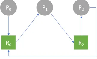
e∈E. The first type is an outgoing edge from process pto resourcer. It represents a request ofrmade byp. Since one resource can be needed by multiple processes at a time, it is possible that there are several outgoing edges from several processes to a single resource. The second type is an outgoing edge from resourcerto processp. It represents thatris currently assigned topby OS. Since there is a constraint stated that one resource can be assigned to at most one process at a time, there must not be more than one single outgoing edge from any resource. Figure1shows an example of process-resource graph of a system at specific time. In Figure1,
V has six vertices represented processes and resources in the system. There are three processes:
P0, P1, andP2. Along with them are three resources: R0,R1, and R2. Each resource can be
described according to its connected edges. R0 is requested byP0 andP2 while it is assigned
to P1. R1 is requested byP1 and it is assigned to no process. R2 is requested byP1 while it
is assigned toP2. Theoretically, a deadlock exists if and only if there is a cycle in the graph in
which processes and resources in the cycle have involved. It is obvious that a deadlock takes place in the given system because we witness a cycle formed byP1,R2,P2, andR0. The cycle
represented an incident thatP1requestsR2whileR2is assigned toP2whereasP2has not been
able to release any resource yet because it still needs R0 to complete its task. Unfortunately,
R0 is assigned toP1at the moment. Hence, this is a deadlock according to its definition [11].
Figure 1: Example of Process-Resource Graph.
have a processpthat requests no resource, i.e., phas no outgoing edge. Similarly, a resource
rthat assigned to no process, i.e., rhas no outgoing edge, can also exist. Figure1 is also an example of incorrect Kripke structure becauseR1 has no outgoing edge. Therefore, something
must be done to transform traditional process-resource graph to a correct Kripke structure before verifying deadlock via model checking. In this paper, we proposed a method to modify a process-resource graph to get a precise Kripke structure. We then illustrated how to generate a model represented the structure as well as constructed a specification using Computation Tree Logic (CTL) formula. Correctness of model, specification formula, and verification result was also discussed.
The paper is organized as follows. Section2 mentions related work. Section3 gives an ex-planation how we constructed our study, which consisted of designing the modification process, designing a specification formula, and dynamically generating a program to verify the model. Section4delivers a result as well as discussion. Finally, Section 5summarizes our work.
2
Related Work
Tanenbaum and Bos [11] defined deadlock as “A set of processes is deadlocked if each process in the set is waiting for an event that only another process in the set can cause” [Tanenbaum, Andrew S and Bos, Herbert, “Modern Operating Systems”, Pearson (2015): 439, Pearson Education Limited]. Leibfried [10] proposed an algorithm to detect potential deadlock by using two matrices, one for adjacency matrix and another one for deadlocks matrix. Multiple matrix-based solutions were invented to detect a deadlock in both single-core systems and parallel systems [3,8].
Model checking is a tool in formal methods that we use for checking some certain speci-fication in a finite state model [1, 5]. With constraint that a set of states must be finite, we can implement model checking to solve multiple finite state computer science problems such as Tower of Hanoi or River Crossing [7]. By the way, the primary objective of model checking is for verifying that whether or not a specification/proposition exists rather than testing. Those specifications that always considered are fairness, liveness, and deadlock. Dijkstra [2] provided a clear difference between testing and verifying as “Testing shows the presence, not the absence of bugs” [Buxton, John N and Randell, Brian, Software Engineering Techniques: Report on a Conference Sponsored by NATO Science Committee, NATO Science Committee, Scientific Affairs Division, NATO, 1970]. However, existing articles [6,12] were dealing with deadlock in general finite state model of software rather than deadlock involved by processes and resources in an operating system represented by a graph.
3
Methodology
3.1
Modification of Traditional Process-Resource Graph
As mentioning in Section1, there is a conflict that a process-resource graph cannot directly be treated as a finite state graph in Kripke structure because there is a possible case that a vertex without any outgoing edge might exist. This incident is usually caused by either a process does not request any resource or a resource is not assigned to any process in the system. This conflict is needed to be solved such that, after modification, the result graph has zero vertex with no outgoing edge.
To fix this issue, we removed every vertex that had no outgoing edge regardless of it was a process or a resource. The reason we did because a vertex that has no outgoing edge cannot be involved in any cycle. Hence, the removed process/resource could have never caused deadlock. A serious consequence might occur when there is a vertex that has an outgoing edge to a removed vertex. We overcame this issue by checking whether or not it has another outgoing edge to another vertex that was not deleted. If it does, we do not need to do anything, otherwise, we added a self directed edge to it. Although adding this kind of edge ruined the semantic of process-resource graph because a process can only request a resource and a resource can be assigned to only a process, this change led us to a qualified graph for Kripke structure since every vertex had at least one outgoing edge. This correct Kripke structure creates many infinite paths. We used the graph in Figure1 as example. Before we started the process, we need to check the correctness of process-resource graph to ensure it did not violate the constraint stated that one resource can be assigned to at most one process at a time. We can check by constructing a corresponding adjacency matrixAthat corresponds to the process-resource graphG= (V, E). The matrixAhasmrows andncolumns wheremandnare numbers processes and resources in the system. Pi∈V represents Process i. Rj ∈V represents Resource j. Each elementAij
where 0≤i < m and 0≤j < nis assigned value according to the following function:
f(i, j) =Aij =
0 (Pi, Rj)∈/E∧(Rj, Pi)∈/E
1 (Pi, Rj)∈E
2 (Rj, Pi)∈E
We applied the function with the example graph. The corresponding adjacency matrix,A, was constructed and illustrated below:
A=
1 0 0
2 1 1
1 0 2
Once we had the matrix, we need to verify that every column contains only single2, which implies that one resource can be assigned to only one process. Applying this rule withA, all three columns satisfied since first and third column had only one 2 atA10andA22, respectively,
and the second column had no 2. Therefore, this instance of process-resource graph was correct and ready to be modified.
For the part of modification, we saw thatR1 is the only one vertex that does not have any
outgoing edge. We then removedR1(Figure2).
After removing R1, the result graph (Figure2) satisfies to be a graph of Kripke structure.
Note thatP1 previously had an outgoing edge toR1 but we did not add a self directed edge to
P1 because P1 has another outgoing edge toR2. The finite state structure depicted in Figure
Figure 2: Modified Graph.
3.2
Modeling the Graph
After we got the qualified graph, we started creating a model. There are three major components of Kripke structure that need to be defined, which are set of states (S), set of transitions (T), and set of atomic propositions (AP). We had already had S andT since we had the graph. S
was equal to a set of vertices. T was equal to a set of edges.
We defined one atomic proposition, state, state ∈ AP. A value of state is a label of the state, e.g., (state =P2) inP2 or (state =R3) inR3. We then generated every transition in
term of propositionstateas illustrated in Table1. Hence, the part of generating a model of the graph in Figure1, which consisted of states, transitions, and atomic propositions was done.
Transition Reason
P0→R0 There is an outgoing edge fromP0to R0
P1→R2 There is an outgoing edge fromP1to R2
P2→R0 There is an outgoing edge fromP2to R0
R0→P1 There is an outgoing edge fromR0 toP1
R2→P2 There is an outgoing edge fromR2 toP2
Table 1: Transitions Defined by Atomic Proposition.
3.3
CTL Formula for Specification
The last step was to define a CTL formula for specification. A property, denoted as q, the generated model must preserve was that: for every stateSi, there must not exist a path that state property (state=Si) holds infinitely often except that a state property
(state=Si) holds in every state of that path. If a deadlock exists, then there must be a cycle in the graph and, at least, one vertex (state) in that cycle must keep showing up infinitely often in one infinite path. However, we had a case that some vertex could have a self directed edge during modification process, which causes a cycle of only itself. Since we do not count this type of cycle as deadlock, we need to ignore it. That is the reason why the property must exempt this incident. Therefore, a deadlock does not occur if and only if the model satisfies the proposed propertyq.
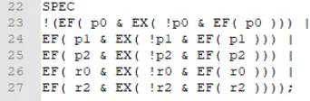
Since there were five states in our generated model (P0, P1, P2, R0, andR2), a CTL formula
representing q in the model can be written as “!(EF(p0 & EX( !p0 & EF( p0 ))) | EF(p1
& EX( !p1 & EF( p1 ))) | EF(p2 & EX( !p2& EF( p2 ))) | EF( r0& EX( !r0 & EF( r0
(state =P i) andri in the formula stands for a state property (state =Ri). In the formula, semantic of F(x) is that there eventually exists a state that satisfies the propertyxin the path and semantic of G(x) is every state in the path satisfies the propertyx. A semantic of X(x) is that the very next state from the current state satisfies the propertyx. A semantic of E(y) is that a stateS|= E(y) ⇐⇒ there exists a pathpt initiated atS andpt|=y.
4
Results and Discussion
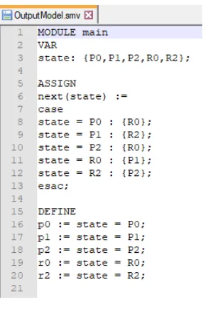
To implement the proposed approach, a Java program that dynamically retrieves a process-resource graph of any size, then generates a model, and finally verifies it for any deadlock existence has been developed. The program retrieves a process-resource graph, represented by adjacency matrix, as input. After the matrix was completely read, the program generates a model by making a modification based on our design that was previously mentioned. Figure 3shows the output model of example graph (Figure 1), which had a corresponding adjacency matrixAas showed in Subsection3.1. Please note that the model was generated using syntax defined by NuSMV [4]. NuSMV is a model checking software application that supports speci-fication using CTL formula. In this implementation, the program also called NuSMV to verify the generated model as well.
Figure 3: Generated Model.
In the Figure3, an atomic propositionstatewas defined along with all possible values, which were five states in the model, in the VAR section. ASSIGN section defined all valid transitions in term of propositionstate. The last section, DEFINE, contained all state properties that were used in CTL formula for specification. The CTL formula was also generated from the program (Figure 4). The generated formula was exactly the same as CTL formula that representing propoertyq in Subsection 3.3. The part of CTL formula was generated at the last section of the model.
Figure 4: CTL Formula for Specification.
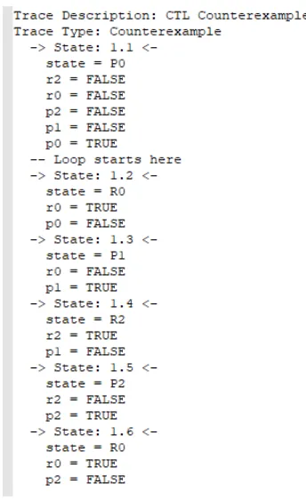
NuSMV would present a counterexample reporting a state that the specification property did not hold. Figure 5 shows the result of verification after calling NuSMV. Since our example contained a deadlock, the result stated that the specification (Figure4) was false.
Figure 5: Verification Result.
Figure 6 shows the counterexample that was detected. From the counterexample, we can see that the propertystate = R2 held in more than one state in the path. Therefore, there evidently was a deadlock andR2was one state that involved.
We did one more case with an ideally bigger operating system that comes with large numbers of processes and resources to double check the accuracy. For this time, we had 5000 processes (P0 toP4999) and 100 resources (R0 toR99). All edges in this graph were randomly generated.
Since it is not possible to illustrate both a graph and an adjacency matrix, we rather briefly describe it as follows: R82was assigned toP30whileP30was requestingR72. However,R72was
currently assigned toP22, who was requesting R82. After we executed the program with this
case, it successfully returned the cycle between these processes and resources (R82, P30, R72,
P22,R82) as showed in Figure7.
Hence, the correctness of both model and CTL formula for specification of deadlock in process-resource graph that dynamically generated by our proposed approach have been showed. Since a complexity of solving a problem via model checking technique was proved to beO(n) [1], using a technique of model checking to solve any finite state problem like deadlock detec-tion in process-resource graph is effective [9] and avoids implementing a complex matrix-based algorithm that is vulnerable from coding bugs, high consumption of computer resources, and lack of code reusability. Only essential part that we have to bear in mind is that both model and CTL formula we generate must be completely rigorous.
5
Conclusion
Figure 6: Execution Sequence as Counterexample.
Figure 7: Partial Execution Sequence as Counterexample.
algorithms.
6
Acknowledgements
References
[1] Christel Baier and Joost-Pieter Katoen.Principles of model checking. MIT press, 2008.
[2] John N Buxton and Brian Randell. Software Engineering Techniques: Report on a Conference Sponsored by the NATO Science Committee. NATO Science Committee; available from Scientific Affairs Division, NATO, 1970.
[3] K Mani Chandy, Jayadev Misra, and Laura M Haas. Distributed deadlock detection. ACM Transactions on Computer Systems (TOCS), 1(2):144–156, 1983.
[4] Alessandro Cimatti, Edmund Clarke, Fausto Giunchiglia, and Marco Roveri. Nusmv: a new sym-bolic model checker. International Journal on Software Tools for Technology Transfer, 2(4):410– 425, 2000.
[5] Edmund M Clarke, Orna Grumberg, and Doron Peled. Model checking. MIT press, 1999. [6] Ivaylo Dobrikov, Michael Leuschel, and Daniel Plagge. Ltl model checking under fairness in
prob. InInternational Conference on Software Engineering and Formal Methods, pages 204–211. Springer, 2016.
[7] Saeed Doostali. An efficient solution for model checking abstract state machine using bogor.arXiv preprint arXiv:1404.2155, 2014.
[8] Dror G Feitelson. Deadlock detection without wait-for graphs. Parallel computing, 17(12):1377– 1383, 1991.
[9] Jon Kleinberg and Eva Tardos. Algorithm Design. Pearson Education India, 2006.
[10] TF Leibfried. A deadlock detection and recovery algorithm using the formalism of a directed graph matrix. ACM SIGOPS Operating Systems Review, 23(2):45–55, 1989.
[11] Andrew S Tanenbaum and Herbert Bos.Modern Operating Systems. Pearson, Pearson Education Limited, Edinburgh Gate, Harlow, Essex, England, 4 edition, 2015.