128 Available online at www.ijiere.com
International Journal of Innovative and Emerging
Research in Engineering
e-ISSN: 2394 - 3343 e-ISSN: 2394 - 5494
Comparative Study on Switching Techniques: A Survey
Janki Jasani
a, Freny Presswala
b, Nirav Bhatt
caCharotar University of Science and Technology Changa, India, [email protected] bCharotar University of Science and Technology Changa, India, [email protected]
cAssi. Prof., Charotar University of Science and Technology Changa, niravbhatt[email protected]
ABSTRACT:
In this paper, we are going to learn diverse exchanging systems which are utilized as a part of multiprocessor framework. The exchanging systems ought to be put by flow control components until data units sending among the switches get to be simultaneous lastly these data units can be sent along the system. The flow control procedures ought to be set alongside the buffer management algorithms to characterize how the buffer demand and get to be free and after that it is uncovered that how the parcels ought to be overseen in the system.
Keywords: Switching techniques, Circuit switching, Wormhole switching, Packet switching.
I. INTRODUCTION
The process of relation among resources can be considered as a hierarchy of services. This hierarchy begins from the physical layer. In physical layer, it is paid further attention to the protocols of link level for sending the messages and the management of the physical channel among neighbour nodes. The switching uses the related protocols in physical layer to implement a mechanism in the network in order to forward the packets. All of routing decisions are made in the routing layer until suitable output channels are chosen in the internodes and an appropriate route is established between source and destination. The design of routing protocols and their characteristics is extensively depended on the provided services through switching layer. The switching techniques are placed next to the flow control mechanisms till information units sending among the routers become simultaneous and harmonic. The flow control mechanisms should be placed next to buffer management algorithms to define how the buffer request and become free [1].
II. BACKGROUND STUDY
When the packet is transferred from any router’s input buffer to its output buffer, this process is known as switching. When a packet reaches to a router, first, it should be investigated and its destination is determined. It means the suitable output channel is defined for packet to forward. This is called routing delay and it includes required time to regulate the switch. When the router switch sets up the router l we want to know the delay rate that a packet can be forwarded through switch. These rates are revealed through propagation delay in the switch and internal delay rate for transfer concurrence between input and output buffer. This delay is called as internal flow control delay. The delay along physical channels is known as external flow control delay. The routing delay and flow control delays, totally, determine accessible message delay through the switch.
A. Performance Metrics[4]
1) Channel width w: No of bits that a physical channel can transmit simultaneously between two adjacent routers, clearly, it is exactly the size of a phit.
2) Channel rate \mu: the peak rate in bits/second at which bits can be transferred over each individual wire of a physical channel.
3) Channel bandwidth B: B=\mu in phits/second, even though it can be defined also as B=w× \mu in bits/second. 4) Channel latency tm: the inter-router latency of one phit, hence tm=1/\mu=1/B in seconds/phit.
5) Startup latency ts: it is the time required for packet validation, framing/unframing and so on, at both the side source and destination. It is a static value, independent of network congestion or distance between nodes. The message size is the main factor on which it depends.
129 encountered during the lifetime of a packet. In the following subsections, we will describe four main switching techniques used in multiprocessor networks. We will not be mentioning startup time ts, since it has a static component common to all 4 techniques. Instead, of that we give formulae for the conflict-free network latency, i.e. assuming a traffic free network. This latency will be known as the base communication latency. For simplicity, we assume that only one header flit is kept in each packet.
Figure 1: General time model of a conflict-free communication between distant nodes[4]
Throughout this section following notation will be used in this paper: 1) w = flit size = phit size = channel width (in bits),
2) M = packet size (in flits),
3) tr = time of routing decision within one router during building a routing path (in seconds),
4) tw = intra-router switching latency once the router has made the routing decision and a path has been set up through the
router (in seconds/phit),
5) tm = 1/B = inter-router channel latency (in seconds/flit). Mtm seconds will be the transmission latency of a packet of M
flits between two adjacent routers. 6) d = the length of a routing path.
III. BASIC SWITCHING TECHNIQUES
A. Circuit switching (CS)
The communication between a source and destination has two phases: connection establishment phase and data transmission phase [4]. By injecting a routing probe, a physical path is established from source to destination before the transmission, which contains destination address and some other control information [1,4]. It needs more than one flit. Let the size of probe in phits be p.
Figure 2: Circuit switching on a path of length 3.
130 Reserving physical links as it is transmitted through intermediate routers, The probe progresses towards the destination node (Figure 2(a)).The path is set up after the probe has reached the destination. Then an acknowledgment flit is sent back (Figure 2(b)). As soon as the acknowledgement is received, the sender transmits the whole message at the full bandwidth of the path. This path forms a HW circuit which is reserved for the whole time of the message transmission (Figure 2(c)).either the destination node or the last bits of the message, releases the circuit [4].
1) Base communication latency: A message of size M is transmitted on distance d which takes time
tCS=d(tr+(p+1)(tw+tm))+Mtm The probe needs time d(tr+p(tw+td)) to reach to the destination, the acknowledgment
takes d(tw+td) to get back, and the data transmission takes Mtm [4].
2) Advantages: when messages are infrequent and long, the message transmission time is longcompared to the path setup time [3].
3) Disadvantages: the physical path is reserved for the duration of the message and may block other messages.When the head flit is blocked at intermediate node, certain resources will be held for a uncertain period of time [3].
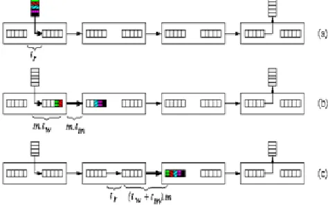
B. Store-and-forward (SF) switching
This technique’s acronym is packet switching. Fixed-length packets are splited from a message, in which every packet consists of flits, starting with the header flit. Every medium has input and output buffers for one whole packet. Every packet is individually routed from source to the destination. One step of the SF switching is called hop. It copies the whole packet from one output buffer to the next input buffer. Routing decisions are taken by each router only after the whole packet was completely buffered in its input buffer [4].
Figure 3: Store-and-forward switching of a packet.
(a)First router makes the routing decision. (b) The packet had performed the first hop to the second router after it has been copied to the output buffer of the first router. (c) The whole packet is received after the second hop[4].
1) Base communication latency: A packet having length M sent to distance d takes time tSF=d(tr+(tw+tm)M) At every router, routing decisions must be made and then the packet hops to the next router, which takes tr+ (tw+tm)M, and this repeats d times [4].
2) Advantages: When messages are short and frequent, a communication link is fully utilized when there are data to be transmitted [3].
3) Disadvantages: Splitting a message into packets produces some overhead. Each packet needs to be routed at each intermediate node [3].
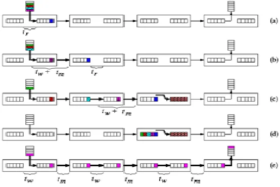
C. Virtual cut-through (VCT) switching
131
Figure 4: Virtual cut-through switching of a packet.
(a) Into the output buffer of the first router, the header flit has moved. (b)The subsequent flits are following the path of the header which has cut through into the second router. (c)The header, along with pulling a chain of flits behind, has cut through into a router where for another communication, its output buffer is reserved. (d) The whole chain of packet flits has
contracted and releasing all previously allocated links the whole packet gets buffered in the first router. (e) Flit pipeline moves towards the destination[4].
1) Advantages: the transmission of the packet header is pipelined with the transmission of the packet payload [3]. 2) Disadvantages: it is necessary to buffer the whole packet at each intermediate router in case the header is blocked [3]
D. Wormhole (WH) switching
The packets are divided into small parts called as flits which are sent along the route. Therefore transmission of different packets cannot be interleaved or multiplexed freely over one physical channel without additional architectural support. The main differences are that routers do not have buffers for the entire packets. Instead, each router has small buffers for one or a few flits. In the network, the header flit again builds the path, which is followed by the other flits in pipeline. The wormhole is formed by the sequence of buffers and links consumed by flits of a given packet. Here, the length of the path is proportional to the number of flits in the packet. It spans the entire path between transmitter and destination. If the header is not able to proceed due to some busy output channels, the whole chain of flits following the header gets stalled, in routers occupying flit buffers on the path constructed till now and also blocking other possible communications. tWH , the
conflict-free communication latency is exactly the same as in previous case switching (see Equation). Hence, it gets proportional to the sum of the packet size and path length [4].
1) Advantages: it is no longer necessary to use the local processor memory to buffer messages, significantly reducing average message latency [3].
2) Disadvantages: In case of blocking, the small buffer size at each node causes the message to occupy buffers in multiple routers, similarly blocking other messages [3].
132 (a) After the routing decision the header is copied to the output buffer. (b) The header flit is being transferred to the second
router and other flits are following the header. (c) The header flit arrived into a router which is busy with some output channel and the whole chain of flits which was following the header along the path got stalled, blocking all its channels. (d)
In case of conflict-free routing, pipeline of flits is being establishing the wormhole across routers[4].
E.
Mad Postman SwitchingVirtual cut through technique improved performance over packet switching by sending continue message flow while comprising the ability to buffer complete message packets. Switching provided further reductions in latency by permitting buffer virtual cuts so that routing can be completely handled within single-chip routers, this trend towards increasing message pipelining is continued with the development of the mad postman switching mechanism as an attempt to realize the minimal possible routing latency per node. Further by pipelining at the bit level, the mad postman switching attempts to reduce the per-node latency. It is assumed that the message will be continuing along the same dimension, when a header flit starts arriving at a router. Therefore, as soon as they are received, header bits are forwarded to the output link in the same dimension (assuming that the output channel is free). Every bit of the header is also buffered locally. As soon as the last bit of the first flit has been received, the router can examine this flit and determine if the message should indeed proceed further along this dimension. If it is to proceed along the second dimension, the remainder of the message starting with the second flit of the header is transmitted to the output along the second dimension. It is said to be delivered to the local processor, if the message is arrived at its destination. In essence, the address is checked after the message is delivered to an output channel, hence the name of this switching technique. Since a message will make at most one turn from one dimension to another, this strategy can work very well in 2D networks. Using mad postman switching technique, the base latency of a message, should be computed as follows:
Tmad postman= th + tdata
Th= D(ts + tw) + max (ts, tw) w T data= max (ts, tw)L
Th= the time which lasts to deliver the header completely. tdata= the time which lasts to deliver data [2].
Figure 6: Time-space diagram for mad-postman switching[1]
IV. VIRTUAL CHANNELS
In the whole switching techniques which have described until now, it was assumed that the message is completely buffered in the input and output of physical channels. A physical channel is able to support several virtual or logical channels which have multiplexed in that physical channel. Every one way virtual channel is implemented with a pair messages that are3 managed independently. Each message can share the physical channel as flit-by-flit. Physical channel protocol should be able to distinguish the virtual channel which uses a physical channel. At first, the virtual channels offered to solve deadlock problem in the wormhole switched networks. Also, the virtual channels can be applied in order to improve the message delay and network throughput [1].
A. Hybrid Switching Techniques
The virtual channels flexibility and availability has led to develop several hybrid switching techniques. These techniques blend the benefits of some basic methods or optimize some metrics related to the performance. In this section we introduce some hybrid switching techniques [1].
B. Pipeline Circuit Switching (PCS)
133 avoiding erroneous parts has achieved through spending setup time of a greater route. A time-space diagram of transferring the message through PCS along there links and in the absence of traffic and error shown in Figure 7 [1].
Figure 7: time-space diagram of transferring message by PCS along three links[1]
The base delay of a PCS message is to be computed as follows: tpcs = tsetup +tdata
tsetup = D(te + tw + ts) +D(ts + tw) tdata = D(tw + ts) + max(ts, tw)([L/W]-1) tsetup: The time which lasts to sets up the route.
tdata: It is the time along the network which lasts until the message is pipelined and reach to the destination [1].
C. Scouting Switching
The scouting switching is a mechanism of combined flow control which has been implemented to provide a special trade-off between the performance and error tolerance. In PCS, the first data flit was injected when the route had setup completely. In order to decrease the overhead originated from route setup time in PCS, in scouting method the first data flit is obligated to remain further back at least K link from the header flit. If K=0, then the flow control will similar to wormhole. While high K numbers guarantee that the route has setup for packets sending. Intermediate K numbers allow data flits to follow the header with keeping a special distance. This make the header flit able to traverse backward easily, if necessary. Figure 8 shows a time-space diagram for a message which has pipelined along 3 link using scouting switching. Parameter K, is called scouting distance or prob leak [1].
Figure 8: Time-space diagram for a message which has pipeline along 3 link using scouting switching[1]
Every time a channel is successfully reserved through the header, a positive affirmation message is given in the returning backward orientation. For every virtual channel, there is a programmable counter. The counter which was related to the virtual channel which was reserved by the header was increased when a positive affirmation was received and it was decreased when a negative affirmation was reserved. The data flits are allowed to advance toward the destination, when the counter number equal K. The space and the distance between the first data flit and the header can be increased to 2 K-1 links. The base delay of scouting switching can be computed as following [1]:
tscouting = tsetup + (ts + tw)(2K - 1) + tdata tsetup = D(tr + ts + tw)
134
V. CONCLUSION
The switching techniques are completed to access to better performance. Virtual cut switching offers message sending as one with a pipeline. The wormhole switching needs some buffers and to decreases the buffer rate in the switches and as it also presents a good pipeline. The mad-postman switching displays bit level pipeline to increases the performance. In VCT and packet switching, the message must be completely saved in the routers. Using the virtual channels there had been no blocked messages in the physical channels and it decreases the delay which was originated from the blocking. But increasing some message multiplexing enhances the delay that data flits are facing. Also, by increasing virtual channels numbers raises the flow control delay in the router and also the delay along the physical channel. The wormhole effect on the message is not avoidable, because the required buffer is very small. In the low traffic load the packet switching has more predictable delay features especially. VCT acts like wormhole when there is low traffic load and it acts as the packet switching when there is high traffic loads. In the low traffics, the wormhole technique has better delay/throughput comparing to packet switching network. In the high traffics, packet switching acts better. All these switching techniques are to be considered as optimistic techniques. In contrary, PCS and scouting are considered to be as pessimistic ones, because data flit is only sent when it is cleared that the flits can advanced forward.
VI. REFERENCE
[1] Hamid Barati, Ali Barati, Ali Movaghar and Arash Azizi Mazreah, “Delay Comparison of Switching Techniques in Interconnection network” in World Acadamy of Science, Engineering and Technology 15 2008
[2] Ahmed Nabih Zaki Rashed, “Signal Delay Control Based on Different Switching Techniques in Optical Routed Interconnection Networks” in International Journal of Advanced Research in Computer Engineering & Technology- Issue 8,Vol 2, August 2013
[3] Dr. Mei Yang, “Switching Techniques” in ECG 702 in Fall 2013
[4] http://pages.cs.wisc.edu/~tvrdik/7/html/Section7.html CS838: Topics in parallel computing, CS1221, Tue, Feb 16, 1999, 8:00-9:15a.m.Available
[5]S. Murali, R. Tamhankar, A. Jalabert, S. Stergiou, L. Benini, D. Bertozzi and G. D. Micheli, "No C Synthesis Flow for Customized Domain Specific Mutli-processor Systems-on-Chips" in IEEE Transactions on Parallel and Distributed Systems in year 2006.
[6]S. B. Furber and T. Felicijan, "An asynchronous on-chip network router with quality-of service (qoS) support" in Proceedings IEEE International SOC Conference in Sept, 2007.
[7]O. P. Gangwal, A. R¢adulescu, K. Goossens, S. G. Pestana, and E.Rijpkema in P. van der Stok, editor, Dynamic and Robust Streaming In And Between Connected Consumer of Electronics Devices in volume 3 of Philips Research Book Series Springer "Building predictable systems on chip: An analysis of guaranteed communication in the thereal network on chip" in year 2006.
[8]K. Goossens, S. G. Pestana, J. Dielissen, O. P. Gangwal, J. van Meerbergen, A Rcadulescu E. Rijpkema, and P. Wielage “Servicebased design of systems on chip and networks on chip” in P. Van der Stok, editor of Dynamic and Robust Streaming In And Between Connected Consumer of Electronics Devices in volume 3 of Philips Research Book Series,Springer in year 2006.
![Figure 1: General time model of a conflict-free communication between distant nodes [4]](https://thumb-us.123doks.com/thumbv2/123dok_us/8873607.1815511/2.612.187.468.492.646/figure-general-time-model-conflict-communication-distant-nodes.webp)
![Figure 6: Time-space diagram for mad-postman switching [1]](https://thumb-us.123doks.com/thumbv2/123dok_us/8873607.1815511/5.612.189.422.360.516/figure-time-space-diagram-mad-postman-switching.webp)
![Figure 7: time-space diagram of transferring message by PCS along three links [1]](https://thumb-us.123doks.com/thumbv2/123dok_us/8873607.1815511/6.612.171.439.452.593/figure-time-space-diagram-transferring-message-pcs-links.webp)
