Analysis of Mobility Management in Wireless
Mesh Networks using Random Walk Model
Meyanand.R.
1,Ramya Dorai.D.
21 PG Scholar,Dept of Computer Science and Eng, Adhiyamaan College of Eng, Hosur
2Assistant Professor,Dept of Computer Science and Eng, Adhiyamaan College of Eng, Hosur
Abstract
A user-based mobility management
scheme for WMN’s namely, the static anchor scheme and dynamic anchor scheme. Both schemes are based can be extended to WMNs that have multiple gateways. We also investigate how catching of location information of MCs can be used to reduce the signalling cost incurred by our proposed schemes. In addition we plan to investigate the proposed schemes under more realistic mobility models the random walk model. The Random walk model is a random based mobility model used in mobility management schemes for mobile communication system. The mobility model is designed to describe the movement pattern of mobile users, and how their location, velocity and acceleration change over time. In random based mobility simulation models, the mobile nodes move randomly and freely without restrictions. To be more specific, the destination, speed and direction are all chosen randomly and independently of other nodes. In this paper we describe the design of a novel network based local mobility management scheme for wireless mesh networks. Our scheme achieves low latency handover (usually less than 20 milliseconds of network layer handover time) when users move from one access router to the next within a network domain. Real time voice and video applications can thus be supported without any service interruption during handover. Our scheme requires no software upgrade on mobile hosts and can work with future MAC-layer technologies and routing protocols. This further reduces the deployment cost of wireless mesh networks.
Keywords: Mobility Management, Random walk model, Wireless mesh networks, low latency handover.
1. INTRODUCTION
Wireless mesh networking have recently attracted much attention as a quick and cheap solution to offer wide wireless coverage for the last-mile Internet connection which is a necessary first-step to enable pervasive mobility services. A wireless mesh network generally consists of a set of mesh nodes that interconnect with each other via
wireless medium to form a wireless backbone. Some or all of the mesh nodes also serve as access points for mobile users under their coverage. One or more mesh nodes have wired connections to the Internet and function as the gateway. Compared to traditional wireless LANs the main feature of wireless mesh networks is their multi-hop wireless backbone.
Wireless mesh networks consists of various types of entities: gateways, mesh routers, access points (AP) and mesh clients. Gateways are the connection points to the wire-line networks. Mesh clients are the terminals users which have no or limited routing function. Wireless APs are the entities in charge of the wireless access for the mesh clients. Stationary mesh routers form a wireless multi hop backbone with long-range high-speed wireless techniques such as WiMAX. In different models a mesh node can contain one or more functional entities, eg., Mesh routers usually implement AP functionalities. When the mobile clients are stationary, with the support of backbone routing, the wireless access for them can be accomplished within a few hops. However, difficulty arises when there are needs for the mesh clients to move across the coverage area of different APs. How to maintain the ongoing connection and how to forward the downstream and upstream packets are not solved by the current standards.
Mobility management consists of location
management and handoff management [1].
Location management keeps track of the location information of mesh clients, through location registration and location update operations.
Handoff management maintains ongoing
connections of mesh clients while they are moving around and changing their points of attachment. Mobility management has been studied intensively for cellular networks and mobile IP networks. A large variety of mobility management schemes and protocols have been proposed for these types of networks over the past years. Comprehensive surveys of mobility management in cellular networks and mobile IP networks can be found [1]. Due to some significant differences in network
architecture, however, mobility management
IP networks are generally not appropriate for WMNs. For example, the lack of centralized management facilities e.g., HLR/VLR in cellular networks and HA/FA in mobile IP networks.
The next generation mobile communications networks networks will provide multimedia services, e.g., voice and video telephony, high-speed Internet access, mobile computing, etc.. Mobility management for providing seamless multimedia communication is one of the most important engineering issues in such a next generation mobile network. The concept of mobility management includes both handoff and location management. Location management is a
basic function to deliver incoming calls
appropriately to the called mobile roaming from place to place [3].
The handoff, on which we focus in this paper, is an essential function for permitting users to move from cell to cell with an ongoing call. There are two major engineering issues concerning handoff. The first is the handoff initiation process. Usually, two types of initiation processes are considered that based on signal strength and that based on carrier-to-interference ratio [5]. The second is call admission control (CAC), which is related to the network resource management. There are two kinds of call request new call and handoff call.
The Random walk model is a random-based mobility model used in mobility management schemes for mobile communications systems. The mobility model is designed to describe the movement pattern of mobile users, and how their location, velocity and acceleration change over time. Mobility models are used for simulation purpose when new network protocols are evaluated. In random-based mobility simulation models, the mobile nodes move randomly and freely without restrictions. To be more specific, the destination, speed and direction are all chosen randomly and independently of other nodes. This kind of model has been used in many simulation studies.
2. RELATED WORK
In this section, we review several network-layer mobility management schemes and discuss the feasibility of using them to support host mobility in the wireless mesh network scenario.
2.1 Mobile IP
Mobile IP and Mobile IPv6 are the IP mobility management schemes standardized by IETF [10, 8]. Each mobile host has a Home Agent (HA). When the mobile host is on the HA serves as an indirection point to forward data packets for the
mobile host and its communication peer. The HA also functions as a location server that maps the mobile host’s home address (identity) to its care-of address (location). This mapping can be notified to the peer so the data packets will flow directly between the mobile host and the peer directly, thereby avoiding the triangle-routing problem.
Mobile IP has two major problems. First, its adoption involves the network operators, the mobile host and its communication peer. Doing
such coordinated software upgrade across
administrative boundaries has proven difficult [12]. Second, when the mobile host is far away from the HA, even though it moves from one Foreign Agent (FA) to the next that is nearby, the handover latency can be very large since the HA is involved. Mesh Cluster implements a Mobile IP based solution in its wireless mesh network. The test results show that the network-layer handover latency is about 600ms, much higher than 150ms, which is required to support uninterrupted real-time applications.
2.2 HAWAII and Cellular IP
The problem of Mobile IP is that each local movement of the mobile host, however small it is, triggers global signalling messages to the HA. Instead of using a macro-mobility management protocol such as Mobile IP for each local movement, a protocol that localizes mobility signalling messages is more preferable to handle local movements in a wireless mesh network domain. HAWAII [11] and Cellular IP [4] are two such micro-mobility management solutions, shown in Fig. 1b. By introducing a Gateway Foreign Agent (GFA) for each domain, they hide the mobility related signalling messages within one domain. This solves Mobile IP’s large handover latency problem. Unfortunately, the design choices of HAWAII and Cellular IP make them unsuitable for wireless mesh networks. Particularly, both involve the mobile hosts in mesh backbone routing and thus implement host-specific routing protocols. This makes the deployment harder, the same problem that Mobile IP faces (see discussion in Section 2.1). Further, they focus on the Internet access communication model and route intra-domain communication traffic also to the GFA. It
is very in inefficient for intra-domain
communication. This is ok for wired networks for which HAWAII and Cellular IP were designed, but can be a problem for wireless mesh networks whose links have limited bandwidth.
2.3 SMesh and iMesh
any unmodified WiFi devices [2]. Its goal is very similar to ours. Seamless handover is achieved by having a group of WiFi access points (called Client Data Group in [2]) serve each mobile host. This group of access points multicasts traffic to the mobile host during handover transitions. This cuts the handover latency to zero at the cost of higher bandwidth use. A more severe problem of SMesh is that it requires all the access points to work on the same channel therefore the mobile host can talk to multiple access points simultaneously. This induces a great cost, since the access points can otherwise work on non-interfering channels to significantly increase the access capacity of the wireless mesh network. In contrast, iMesh adopts an ad hoc routing based solution. The main drawback is that the routing table size in the mesh routers increases linearly with the number of mobile hosts. Plus, every movement of a mobile host causes routing table updates in some of the mesh routers. Software upgrades at both mesh routers and mobile hosts are also inevitable.
3. ANT DESIGN GUIDELINES
3.1 Ant High-Level Design
According to the discussion in Section 2, to find acceptance, a mobility management scheme has to achieve at least two goals: 1) It must facilitate easy deployment; 2) It must satisfy all the application requirements, particularly those of real-time voice and video communications. To achieve the first goal, we try to involve as few parties in the deployment game of Ant as possible. We choose to place as much as possible mobility functionalities inside the wireless mesh network, as opposed to the end host based solutions such as Migrate [14, 16]. Doing this will minimize the required functions from MHs. At the extreme, MHs only need to signal an event as long as it obtains a new MAC-layer connection (such as a WiFi association event). The benefit of such design is that it can accommodate a wide variety of mobile terminals, due to its minimalist requirement of MHs, thus reducing deployment cost. It is also easier to upgrade the mobility service since it requires changes only at the network side. Adding new functionalities such as security also seems straightforward. To achieve the second goal, the key problems are how to realize low-latency handover between the RAPs (less than 150ms to support perceptionally uninterrupted voice and video applications) and how to minimize packet loss rate during the handover process. The total handover latency includes three parts: a) the layer-2 handover time, which is what an MH takes from releasing its old MAC-layer attaching point to obtaining a new one. This is not under the control of a layer-3 mobility management scheme such as Ant; b) the time the MH needs to reconfigure its IP
stack, such as updating its IP address and gateway setting; c) the layer-3 handover time, which is what the mesh network takes to switch the MH’s packet forwarding path from its old location to the new one. Ant does the following to minimize the total handover latency. Minimizing this latency also helps reduce the packet loss rate caused by the handover.
First, unlike Mobile IP, HAWAII, and Cellular IP that use periodic signalling messages (or user data traffic if any) to trigger layer-3 handover, Ant uses the MAC-layer association event to do so (e.g., RAPs providing WiFi access can easily capture MHs’ WiFi association request). Comparing to periodic signalling messages and user data traffic, the MAC-layer trigger is more timely but consumes no extra bandwidth.
attaching RAP, the MH’s RAP to the CN’s RAP, and the CN’s RAP to the CN. This makes supporting the case where both MH and CN are mobile terminals very straight-forward, like ROAM [17].
Third, in Ant each RAP maintains a list of all its physical neighbours. When an MH hands over from one RAP to another, the old RAP sends out the MH’s context information to all its neighbours, including the new RAP. (If the new RAP happens not to be in the old RAP’s neighbour list, the new RAP will query the location server which RAP the MH comes from.) Then the new RAP asks the old RAP to establish a temporary bi-directional tunnel between them to carry the packets for the MH. As a consequence, the layer- 3 handover latency is one round-trip time between the two neighbouring RAPs and the time to set up the temporary tunnel. The tunnel setup time can be avoided by pre-setting up the tunnels between all the neighbouring RAPs this can be done without a scaling problem because the cost of setting up a tunnel is very small and the number of neighbouring RAPs in a wireless mesh network is not large (usually less than six which is the case for full access coverage). Further, the RAPs and the MHs can buffer application traffic to reduce the packet loss rate during handover. In Ant only RAPs implement this function since the MHs are not required to upgrade any of its software.
4. ANT PROTOCOL DETAILS
Now we are ready to give a detailed description of Ant. It mainly includes three procedures: an MH joining a mesh network, communication initialization between an MH and its CN, and an MH handover from one RAP to the next.
4.1 Mobile Host Joining Network
In a wireless mesh network domain, a location server maintains a location database to keep track of all the MHs’ location information. Each database entry is a triple mapping of {MH-ID, MH-IP, MH-RAP}. The MH-ID is the MAC address of the MH’s network interface, such as WiFi. The MH-IP is the MH’s IP address. The MH-RAP is the IP address of the RAP to which the MH is currently attaching. When an MH joins a network domain, it first performs MAC-layer association with a RAP in the network. Through this association process, the RAP knows the MH-ID, i.e., the MAC address of the MH’s network interface. Then the RAP sends a location update message, which contains the MH-ID, to the location server. If the location server finds no entry for the MH-ID in its location database, it knows that the MH is a newly joined host. The location
server then asks the DHCP server to allocate a new IP address, i.e., MH-IP, to the MH. The MH-IP is included in a DHCP message, which is sent back to the MH via the standard DHCP protocol. Within one network domain, the IP addresses belonging to the same IP subnet are allocated. The GRAP is set as the default gateway. If the record of the MH already exists in the location database, the location server updates the record for the MH and sends back a location update acknowledgement message to the RAP.
4.2 Communication Initialization
A MH can communicate with a CN in the
same network domain (i.e., intra-domain
communication), or a CN outside of the network domain (i.e., inter-domain communication). We first discuss the communication initialization procedure for the intra-domain communication. Before sending out data packets, the MH issues an ARP request message to resolve the MAC address of the CN-IP. Upon receiving such message, the attaching RAP (RAP-MH) queries the location server with CN-IP as the key. The location server looks up its location database (it will find the CN-IP in this case) and returns the current attaching RAP of the CN (i.e., the CN). Then the RAP-MH will talk to the RAP-CN to setup a bi-directional tunnel between them and add a corresponding route entry to forward data packets for the MH and the CN. Next, the RAP-MH replies to the ARP request message from the MH with its own MAC addresses to intercept the packets destined to the CN. The communication between the MH and the CN now can start. Two optimizations are due to improve the performance of the above communication initialization process. First, to minimize the tunnel-setup delay, the tunnels between all the (frequently communicating) RAP pairs can be set up prior to the communication at the cost of increased RAP memory use. Second, a RAP can build a local cache to save query reply from the location server, which can be used to for later communications between the MH and the same CN if the CN is fixed (e.g., the Internet web accessing scenarios). When an MH communicates to a CN outside of its network domain, the location server will not find a matching CN-IP. It then replies with GRAP (the default gateway) as the RAP-CN. After that all the packets destined to the CN will be sent to the GRAP and then forwarded to the CN.
4.3 Fast Handover
Ant implements a fast handover
mechanism assisted by neighbour RAP
solicit message. Those that reply are included in the initial neighbour list of the RAP. As an MH hands over from one RAP to another, from the query to the location server, the new RAP knows that the old RAP is its neighbour and vice versa. As a result, the neighbour list gets gradually refined thanks to MHs’ mobility. Similar techniques are discussed in [7].
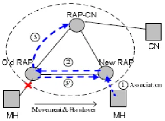
Figure 1: Fast Handover Timeline
Ant’s fast handover includes of two parts: 1) setting up a temporary tunnel, and 2) re-routing. Suppose an MH hands over from the old RAP to the new one while the MH has an ongoing communication with its CN. The CN is attaching to the RAP-CN. Fig. 1 depicts the detailed timeline of this process. Upon detecting the MH's MAC-layer de-association event, the old RAP starts to buffer packets destined to the MH-IP and sends a handover notification message to all the RAPs in its neighbour list. When the new RAP captures the MAC-layer association or re-association event of the MH-ID, it looks up its local message cache to see if it has received the handover notification message. If so, from the matching entry it knows the old RAP to which the MH was previously attached. (Otherwise it will know this by querying the location server.) Then the new RAP sends a handover confirm message to the old RAP and a location update message to the location server simultaneously (Step 1). The location server deals with the location update message in the same way. Once the handover confirm message is received, the old RAP stops buffering the packets for the MH and a temporary bi-directional tunnel is set up between the old RAP and the new RAP to forward the buffered and later-coming packets for the MH (Step 2). After this, the old RAP informs the RAP-CN about the change of MH's attachment to route the MH’s packets directly to the new RAP (Step 3). At the same time, the old RAP also sends a message to the new RAP requesting to route the packets destined to the CN to the RAPCN directly (Step 3). After these are done, the new route between the new RAP and the RAP- CN is set up and the whole Ant handover process completes.
5 IMPLEMENTATION AND EVALUATION
In this section we describe the prototype implementation of Ant and the experimentation results from an internal testbed.
5.1 Ant Prototype Implementation
We build RAPs with desktop PCs. Each RAP installs two 802.11b wireless interface cards. One wireless card runs in ad hoc mode on the same channel, connecting the RAPs together to form a mesh network. The other operates in master mode, providing wireless access to users. All the RAPs run Fedora Linux, OLSR routing protocol [15] and the Mad WiFi driver. The mesh network consists of three RAPs located in a 35m x 20m room in our labs. Fig. 4 shows the network topology. The MH and the CN used in our experiments are laptop PCs running Fedora Linux. The RAPs’ wireless access coverage interfaces are set with different ESSIDs to make it easier to trigger handover in our indoor testbed by manually switching between different ESSIDs. We implement the Ant protocol in the RAPs’ Linux user space.
Figure 2: The Mesh Network Testbed Topology
The location server runs on RAP2 in the testbed, see Fig. 2. To measure the network-layer handover latency, we setup an audio stream from the MH to the CN. We trigger the MAClayer handover by manually switching the MH’s attaching ESSID from RAP3’s to RAP1’s. Since the Ant signalling messages are transmitted over these three wireless links, we use a third laptop to capture all the packets between the three RAPs. We calculate the handover latency by time-stamping the signalling messages. Ant in this paper only addresses layer-3 handover latency, while the layer-2 handover latency is from the Linux WiFi driver in our experiments. Fig. 5 depicts a typical
handover timeline measurement. The MH
RAP1-RAP3-RAP2-CN and then settles on the path MH-RAP1-RAP2-CN.
Table 1: A Typical Handover Tmeline Measurement
We can see that the layer-2 handover time is 29.1ms, while the layer-3 handover time is only 3.4ms. The layer-2 handover time is measured between RAP3’s sending out a handover notification message to its neighbours and RAP1’s sending out a location update message to the location server (RAP2). The layer-3 handover time is measured between RAP1’s sending out a handover confirm message to RAP3 and RAP3’s sending out a handover confirm acknowledgement message to RAP1 (at the same time the data packet also arrive at RAP1). A typical handover timeline measurement Table 1 includes more experiment results, which shows that the layer-3 handover latency of Ant is on average 2.7ms. Of course this measurement depends on our testbed topology. In general, as shown in Fig. 3a in Section 4.3, the layer-3 handover latency is decided by the round-trip time between the two neighbouring RAPs. Since in a wireless mesh network, we can maintain a small average number of hops between any pair of neighbouring RAPs, the RTT can thus be kept very small. For example, keeping an average number of 3 hops with each hop taking 3ms can achieve 20ms latency for the layer-3 handover. This means that the Ant layer-3 handover performance can scale to large-size wireless mesh networks in practice.
However, the Ant signalling messages are all transmitted over the air. The wireless link condition can vary significantly, and this will greatly influence the handover performance. In our experiments, we observed signalling message retransmissions due to wireless link quality's sudden changes that contribute to the variation of handover latency. Furthermore, if the wireless mesh backbone is congested, the latency could be much larger. To make Ant working under such scenarios, we used a class based scheduling policy, such as DiffServ [13] and IEEE 802.11e [9], with
the Ant signalling messages given higher priority than other traffic. Fig. 5 and Table I only show the measurements of handover latency with traffic from the MH to the CN. In the case when the traffic is from the CN to the MH, the handover process is the same but the buffer function at the RAP-MH can help reduce the packet loss rate during handover.
5.3 Handover Impact on TCP Traffic
Now we evaluate TCP performance under Ant and compare it with that of Mobile IP. A TCP stream runs between the MH and the CN either can be a receiver. It shows TCP throughput at the receiver. Ant keeps TCP throughput very stable and nearly unaffected by handovers, while with Mobile IP, TCP throughput has periodical, significant drops, which are caused by the lost packets during handovers.
6. CONCLUSION AND FUTURE WORK
This paper presents a novel network-based, intra-domain local mobility management scheme called Ant. Using experiments based on a working prototype we develop, we demonstrate that, with Ant, mobile users can immediately enjoy the benefits of seamless mobility without any software upgrade on their terminals. Ant achieves very low handover latency, which makes
uninterrupted mobile real-time applications
possible. We have extended Ant to support mobility when users move across wireless mesh network domains. We are working on adding security functionality in Ant.
7. REFERENCES
[1] I. F. Akyildiz et al., “Mobility Management for Next Generation Wireless Systems,” Proc. IEEE, vol. 87, no. 8, Aug. 1999, pp. 1347–84.
[2] Y. Amir, C. Danilov, et al., Fast Handoff for Seamless Wireless Mesh Networks. In Proc. of MobiSys'06, June 2006.
[3] D. G. Jeong andW. S. Jeon, “Probabilistic location update for advanced cellular mobile networks,” IEEE Commun. Lett., vol. 2, pp. 8–10, Jan. 1998.
[4] A. Campbell, J. Gomez, S. Kim, A. Valko, and C. Wan, Design, Implementation and Evaluation of Cellular IP.
IEEE Personal Communications, June/July 2000.
[5] W. C.Y. Lee, Mobile Cellular Telecommunications, 2nd ed. NewYork: McGraw-Hill, 1995.
[6] R. Ramjee, T. La Porta, S. Thuel, K. Varadhan, and S. Wang, HAWAII: A Domain-based Approach for Supporting Mobility in Wide-Area Wireless Networks. In
Proc. of ICNP’99, November 1999.
[7] M. Shin, et al., Improving the Latency of 802.11 Hand-offs Using Neighbor Graphs. In Proc. of MobiSys'06, June 2004.
[8] D. Johnson, C. Perkins, et al., Mobility Support in IPv6,
IETF RFC 3775, June 2004.
Specific Requirements – Part 11: Wireless LAN Medium Access Control (MAC) and Physical Layer (PHY) Specifications - Amendment: Medium Access Method (MAC) Quality of Service Enhancements. November 2005 [10] C. Perkins, IP Mobility Support. IETF RFC 2002, October 1996. [15] K. Ramachandran, M. Buddhikot, et al., On the Design and Implementation of Infrastructure Mesh Networks. In Proc. of First IEEE Workshop on Wireless
Mesh Networks, September 2005.
[11] R. Ramjee, T. La Porta, S. Thuel, K. Varadhan, and S. Wang, HAWAII: A Domain-based Approach for Supporting Mobility in Wide-Area Wireless Networks. In
Proc. of ICNP’99, November 1999.
[12] IETF NETLMM Working Group.
http://www.ietf.org/html.charters/ netlmm-charter.html.
[13] S. Blake, D. Black, et al., An Architecture for Differentiated Services. IETF RFC 2475, December 1998. [14] A. Snocen, et al., An End-to-End Approach to Host
Mobility. In Proc. Of MOBICOM'00, August 2000. [15] T. Clausen and P. Jacquet, Optimized Link State Routing
Protocol. IETF RFC 3626, October 2003.
[16] C. Guo, et al., End-to-End Mobility Support in IPv6 Using Peer-to-Peer Technologies. MSR Asia TR-29-2004, 2004. [17] S. Zhuang, et al., Host Mobility Using an Internet
Indirection Infrastructure. In Proc. of MobiSys'03, May 2003.
[18] I. Stoica, et al., Internet Indirection Infrastructure. In Proc.