Design and Implementation of an Intelligent
Device for Home Automation
Adedamola Wuraola
1, Akindele Segun Afolabi
21Telecommunications and Electronics Engineering, Sheffield Hallam University, Sheffield 2Electrical and Electronics Engineering, University of Ilorin, Nigeria
Abstract— In this paper, we introduced a home automation
system with redundancy. Focus was shifted more on redundancy other than the use of sensors due to some reliability issues and common deviations associated with sensors. We went ahead to include remote connection to the home by the use of wide area network(WAN) connection, a timer and a computer system which was programmed to monitor, control as well as serve as an override device. A small survey was carried out to see the discrepancy on the knowledge of home automation among the people leaving in South-West part of Nigeria.
Keywords— redundancy, sensors, WAN, override, survey.
I. INTRODUCTION
Conserving electricity has become increasingly important as energy rates and shortages have increased and will continue to increase, therefore, the need for automatic control of electrical appliances. Due to the recent introduction of prepaid meter in Nigeria, which is the pay as you consume type of electricity billing method, there arise a need to reduce the wastage of electricity and billings in various homes across the country. It should be known that the use of automation for electrical appliances is still a new technology in most part of Nigeria and have not been fully embraced by the populace as shown by the result of the survey carried out. Therefore, there is a need to introduce a simple, cheap and easy to use home automation device whose electricity consumption will be very minimal.
The intelligent device developed and constructed makes automatic controlling and monitoring of electrical appliances present in the home possible. Thereby reducing electricity wastage and it also introduces conveniences when it comes to operating the appliances. From the survey, the result shows that, lighting and cooling appliances are the most commonly used and most available in homes, therefore this intelligent device was developed towards solving wastage coming from such appliances.
The developed system will reduce wastage of electricity because of the sensors present in the intelligent device which will in turn reduce the monthly electricity bills expected to be paid by individuals. There is no need to actually be present before the intelligent system will perform its duties. Also the computer system will save time and energy because a single button can control the whole lighting and cooling appliances present in the home. Therefore, the constructed device will enable electrical appliances to function more efficiently, conservation of resources to be précised electricity bills. Also it will
II. BENEFITS OF THE DEVELOPED INTELLIGENT DEVICE
The increasing ubiquity of heterogeneous computing devices such as laptop computers, palmtops, mobiles etc. shows that users prefer a ubiquitous access of a system rather than to be uncomfortably forced to go physically to the nearest control point [1]. Hence, there is a need for a system to perform controlling and monitoring roles for users. Home automation as we all know have various advantages but in this section we will be discussing the advantages of the intelligent device developed to the users.
1) Decrease in electricity bills for users because the electrical appliances will only be active only when needed due to the sensors incorporated in the intelligent device.
2) It saves time and also enhances convenience for the users because a single click on the computer system can put “OFF” every electrical appliances present in the home.
3) Moreover, since you can monitor the state of the appliances from the display unit of the computer system, it increases security and help prevent unforeseen harmful circumstance like fire outbreak.
III.DESCRIPTION AND WORKING PRINCIPLE OF THE
INTELLIGENT DEVICE
The intelligent device was based strictly on controlling and monitoring the lighting and cooling systems present in the home, this is so because lighting has by far been the most popular and common use of home automation as shown by the survey. Therefore in developing countries like Nigeria where home automation have not being fully embraced it is important to start from the most common and important electricity consuming and readily available appliances in the homes like lighting bulbs and cooling fans.
The intelligent device comprises of the microcontroller, the light sensing unit, temperature sensing unit, computer system unit and the relay switching unit. The function and how each of these components works is given in full details in the next sections.
Fig. 1 Block diagram of the intelligent device
A. Hardware design stage
The hardware aspect of this intelligent system is divided into four. The next section talks more on each.
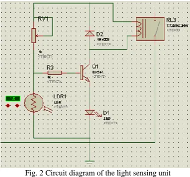
1) Light Sensing Unit: Lighting automation in this work is the act of controlling all the light fittings in the home, whether they are located in the bedroom, the kitchen or the security lights from a single location based on three technologies namely: light sensor, timer, and computer system. In this work, the intelligent device, whose light sensing unit consists of a Light Dependent Resistor (LDR), was used to sense the level of light and either trigger “ON” or “OFF” the lighting bulbs.
A LDR is a special type of resistance whose value depends on the brightness of the light which is falling on it. It has a resistance of about 1 mega ohms when in total darkness and a resistance of only about 5 kilo ohms when brightly illuminated. A potential divider circuit was made with the LDR and 100K variable resistance connected in series. We know that voltage is directly proportional to conductance; so low voltage will be dropped across the LDR when it is light up and high voltage in darkness. This divided voltage is passed to the base of the BC547 NPN transistor. Variable resistor is so adjusted that it crosses potential of 1/3rd in brightness and fall below 1/3rd in darkness. Sensitiveness can be adjusted by this variable resistance. When no light falls on LDR, the resistance of LDR becomes high so almost the entire voltage drop takes place across it and the base of the transistor is at low potential. So the transistor does not get biased nor does it conduct, hence switching off the light emitting diode as shown in the circuit diagram in Fig. 2. The sensitivity of the circuit can be adjusted by varying the variable resistor. In other words, the variable resistor is used to fine tune the level of darkness required before the LED lights up. The circuit diagram is illustrated in fig. 2
Fig. 2 Circuit diagram of the light sensing unit
The limiting resistor should be at least 1 k ohms to protect the transistor from being damaged by excessive current. The transistor BC547 has an Ic (collector current (DC)) of 100 mA from the manufacturer’s datasheet. The DC current gain (hFE) is about 100 from the manufacturer datasheet. Hence the base current is calculated as shown below.
But
IE =Ic + IB …………1.1 And
Ic=
I
c
hFE …………1.2Therefore,
FE c B
h
I
I
……….1.3
2) Temperature sensing unit: The temperature sensing unit deals with control of the cooling system in the house. It consists of an LM35DZ which sensed the temperature level of the environment and either trigger “ON” or “OFF” the cooling systems and an ADC0804 analog-to-digital converter. The analog-to-digital converter is used to convert the analog output of the temperature sensor into digital form and readable by the microcontroller. The block diagram of the temperature sensing unit is illustrated in Fig. 3.
F
Fig
Fig. 3 Block Diagram of Temperature Sensing Unit LM35
DZ
ADC
0804
TO MCU
A/D Converter Temperature
3) Relay Switching Unit: This unit is made up of Ultra Low Noise device and relays.
A. Ultra low noise device
The ULN2803 is used in this work which is an integrated circuit chip with a high voltage/high current Darlington transistor array. It consists of eight NPN Darlington transistors. This is ideally suited for interfacing below low logic level digital circuitry (such as TTL, CMOS) and the higher current/voltage requirements of lamps, relays and other similar loads for a broad range of computer. Therefore, we need ULN device in this work because we interface the microcontroller with the set of relays. The normal output voltage rating for ULN2803 is 50V and operating temperature range between 0 to 70oC which makes it perfect for this work.
B. Relay
A relay is an electrically operated switch. A relay has ±25% of voltage that it can operate with. Therefore for a 6 V relay,
25% of 6 V 25/100 X 6 = 1.5 6 V-1.5 V = 4.5
The 6 V relay is readily available in the market and will make the construction more convenient and easy by just using only the 5V power supply.
A relay is composed of a coil and a contact. When the current reaches a certain point, the magnetic field becomes strong enough to move the contact. The movement of the contact creates either an open circuit or a closed circuit between the relay’s output pins;
Therefore using the relation
V = IR ………1.4
The triggering current through the coil can be computed as
relay
R
V
I
……….1.5
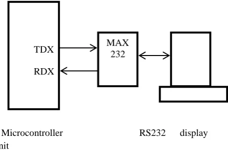
4) Computer unit/Display Unit: The display unit is made up of the personal computer. In this project work, the PC is acting as both the display unit as well as the control unit. The state of all the lighting bulbs and the fans can be viewed from the personal computer (PC). Also the appliances can be controlled by some of the buttons of the PC. The display unit can be viewed as well as controlled from any location in the world by the use of remote access software known as “Team Viewer”. This software is open source and available online for download. The computer system connected to the constructed circuit will always act as the server while any other computer system from any location can log in to control the light and cooling unit
in the home. The block diagram of the display unit is illustrated in Fig. 4.
Microcontroller
RS232 display unit
Fig. 4 Block diagram of the display unit
The MAX232 IC is used to convert the TTL/CMOS logic levels to RS232 logic levels during serial communication of microcontroller with the PC. The controller operates at TTL logic level (0-5 V) whereas, the serial communication in PCs work with about 18.5 V and above.
B. Software development stage
Microcontroller Unit: This is the heart of the intelligent device which takes in the data from the other units and process them based on the predefined codes burned on the microcontroller.
The 8051 family of microcontroller is used. The AT89C51 is used which contains flash programmable and erasable memory (PEROM) such that the program memory can be reprogrammed without erasing the chip content with ultraviolet light. The characteristics of the AT89C51 include; 40 pins, 4 K flash program memory, 128 K RAM data memory, 2 timer/counters and 32 I/O pins. The language used is C language and burned to the microcontroller by the use of a top programmer.
The program description language of each unit is discussed below.
1)Temperature sensing unit:
Main program START
Clear display
Initialize microcontroller interrupts and A/D converter
Start conversion
END
Initialization function START
Set A/D WR and RD pins to 1
Set INT1 to accept interrupts on high-to-low
MAX 232 TDX
Enable INT1 interrupts
Set microcontroller to accept interrupts END
Start conversion function START
Set WR pin to 0 Set WR pin to 1 END
External interrupt INT1 service routine START
Set RD to 0 Read temperature Convert to mV Set RD to 1
END
2) Light sensing unit:
WHILE
It is dark
Switch ON the security light Start timer
OFF
When time = 5minutes Stop timer
Switch OFF the security light
3) Computer system (serial interface):
START
Initialize serial port
Display “THE MENU PAGE” For KEY = 1 to 4
IF appliance is ON
Display “Appliance is now OFF” Appliance = OFF
ELSE
Display “Appliance is now ON” Appliance = ON
IF KEY = 5
Check for the temperature value Display “Temperature is” ELSE IF
KEY = 6
Display the help page ELSE IF
KEY =?
Check the state of all appliances
Display the current state of all appliances END
TABLE 1
FUNCTIONS OF THE PREDEFINED KEYS Numeric
Keys
Functions
1 Switch ON/OFF main lights 2 Switch ON/OFF cooling units 3 Switch ON/OFF security lights
4 Switch ON/OFF all appliances (lighting and cooling systems)
5 Check for the temperature value 6 Display the menu page
7 Override previous control instruction delivered to the cooling unit
? Check the state of all appliances
C. Working operations
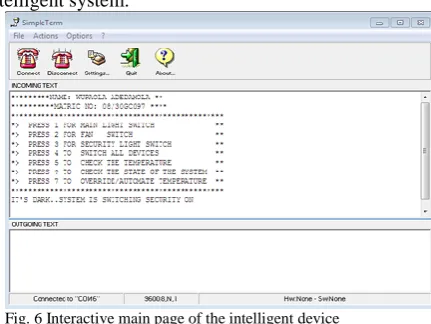
Figure 6 shows the main and interactive page of the intelligent system.
Fig. 6 Interactive main page of the intelligent device
The LDR automatically sense the light intensity and switch ON the security when it dark and this triggers the timer and after the predefined time the security light goes OFF. The temperature sensor senses the temperature of the environment and switches ON the fans when it is hot (that is whenever the temperature level is 27oC and above) and switches OFF the fans when it is below 27oC. The full working operation of the intelligent device is illustrated in fig.7
Fig. 7 Full working operation page
Furthermore, the remote connection to the system was tested successfully by the use of a remote access open source program known as “Team Viewer”.
Conclusion
In this paper, we have designed and constructed an intelligent device for monitoring and controlling the lighting and cooling electrical appliances present in the home. We built our intelligent device using three technologies which are sensors, WAN and computer system to automatically and remotely control and monitor the state of the electrical appliances present in the home. From the small survey sample taken, we can conclude that the use of home automation in Nigeria is still at its prime age. Therefore, this system will give the users a good point to start from. As time goes on, the intelligent device can be expanded to support every other appliance in the home.
Acknowledgment
I am eternally grateful to A.S. Afolabi and David Adu, for their great help all through the development and writing of this project.
REFERENCES
[1] R.C. Elsenpeter, "Build Your Own Smart Home,"Osbourne:
McGraw-Hill, 2003.
[2] D. Ibrahim, Microcontroller Projects in C for the 8051, 1st ed., Oxford: Newness, 2000
[3] A. Wuraola, "Design and Construction of an Intelligent
Device for Home Automation," B.Eng. thesis, University of Ilorin, Ilorin, Nigeria, May 2013.
[4] A. Goswami, T. Bezboruah, K.C. Sarma, "Design of an
Embedded System for Monitoring and Controlling Temperature," Proc. of International conference on Emerging Technologies and Applications in Engineering.
[5] A. R. Delgado, R. Picking and V. Grout, "
Remote-Controlled Home Automation Systems with Different Network Technologies," Centre for Applied Internet Research (CAIR), University of Wales, NEWI, Wrexham, UK.
[6] "LM35DZ, data sheet," National Semiconductor Corporation
website [Online]. Available: http://www.national.com.
[7] "ULN2803, data sheet," National Semiconductor
Corporation website [Online]. Available:
http://www.national.com.
[8] "ADC0804, data sheet," National Semiconductor Corporation
website [Online]. Available: http://www.national.com.
[9] "AT89C51, data sheet," [Online]. Available:
http://www.atmel.com.
[10] G. James and F. Zoe, "Home Automation and Wiring,"
[Online]. Available: