Copyright © 2013 IJECCE, All right reserved
Optimal Scheduling of Task on a Digital Microfluidic
Biochips
Debasis Mandal
Asstt. Prof., Deptt of CSE IMPS College of Engg. & TechnologyEmail: [email protected]
Rahul Karmakar
Asstt. Prof., Deptt of CSE IMPS College of Engg. & TechnologyEmail: [email protected]
Akhil Kr. Das
Asstt. Prof., Deptt of CSE IMPS College of Engg. & TechnologyEmail: [email protected]
Abstract–In this paper a novel placement and scheduling algorithm for digital micro fluidic bio-chips has been presented. Micro fluidic-based biochips are soon expected to revolutionized clinical diagnosis, deoxyribonucleic acid (DNA) sequencing, and other laboratory procedures involving molecular biology. In contrast to continuous-flow system that relies on permanently etched micro channels, micro pumps, and micro valves. Digital micro fluidic offers a scalable system architecture and dynamic re configurability. Groups of unit cells in a micro fluidic array can be reconfigured to change their functionality during the concurrent execution of a set of bioassays. As more bioassays are executed concurrently on a biochips, systems integration and design complexity are expected to increase dramatically. We proposed a heuristics tree based algorithm to solve the problem of Placement & Scheduling for Microfluidic Biochips which is known to be NP complete. Experimental results show that the proposed algorithm is capable of efficient solution of the given problem posed as a task graph, and the dimension of the biochips and the time required for each biochips operation.
Keywords – Microfluidic, Biochips, Placement, T-Tree, Task Graph.
I. I
NTRODUCTIONThis paper presents a novel scheme for placement and scheduling of tasks on a microfluic biochips. Droplet based microfluidic biochips [6] have recently emerged as Microsystems for safety-critical biomedical applications. A heuristics tree based algorithm [7] is proposed to solve the problem which is known to be NP-complete. Experimental results show that the proposed algorithm is capable of efficient solution of the given problem posed as a task graph, and the dimension of the biochips.
II. P
ROBLEMS
TATEMENTSequencing graph G= {V, E} is shown in figure 1&5 where V = {v1, v2…., vm} represents a set of m assay operations and E = (vi, vj), denotes the data dependencies between two assay operations. The second one is the size of the each operation (width & height).third one is the completion time of each essay operation and total available assay size (as a m*n matrix)
III. P
ROPOSEDS
CHEMEThe module placement problem for electronic design is known to be NP-complete [5]. The micro fluidic placement problem is also NP-complete microfluidic
biochips are based on the manipulation of discrete liquid particles called droplets [1] Operation of droplets is based on principles of electrowetting on dielectric [3]. In this paper, I model each task as a 3D-box [4] and deal with the placement problem .we present a tree-based data structure, called T-trees [2] to represent the spatial and temporal relations among tasks. Each node in a T-tree has at most three children which represent the dimensional relationship among tasks as follows. If node nlis the left
child of node np, task vlis placed at same position as task
vp in the T+ direction. If node nm is the middle child of
node np, task vm is placed in the Y + direction of task vp,
with the t-coordinate of vm being equal to that of vp. If
node nris the right child of node np, task vris placed in the
X+ direction of task vp, with the t and y-coordinates being
equal to vp.
Fig.1. Dependency Graph
Fig.2. Placement of tasks in biochips as a 3-D
Copyright © 2013 IJECCE, All right reserved Fig.4. Resulting T-Tree
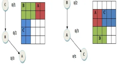
Task vl(D)is placed at B’s(Vp) coordinate and Starting time of D (Vl) is starting time of B (Vp) plus Ending time of B (Vp).task A (Vr) can be start at the Same time as task B (Vp) started but same Y Co-ordinate. As indicated in figure 3 & 4.
T-tree operations:
T-tree operations are
1) Move:
move a task to another place.2) Swap:
swap two tasks. The Move operation needs theInsertion and Deletion operations for inserting and
deleting a node to and from a T-tree.
3) Deletion:
The target node for deletion could be as follows:• Case 1: a leaf node.
• Case 2: a node with only one child. • Case 3: a node with two or three children. For the first case, the target node is simply deleted. For Case 2, we delete the target node and place its only child at the position of the deleted node such that precedence constraints & storage constraints is not violated. This operation can be done in constant time. For Case 3, the target node ni is deleted, and one of its children nc is moved to the original position of ni such that precedence constraints & storage constraints is not violated. Then we move one child of nc to the original position of nc.This process proceeds until a leaf node is encountered. This operation takes O (h) time, where h is height of the T-tree.
Insertion:
New task can be inserted, into the internal position (position between two nodes) and the external position. (Pointed by NULL pointer)Swap: For swapping two nodes in a T-tree, we simply
exchange their parent and child nodes such that precedence constraints & storage constraints is not violated.
IV. A
LGORITHM& F
LOWCHARTA. Algorithm
Algorithm Tree construct (G(V,E),A[][],t[]) G (V, E) = sequencing graph
m*n = total array size t = time for each operation
C[t] = array containing all completed task in the tree A [t] = array containing all the task in the tree which is not completed so far
1. Begin
Sort all the task according to their time (heuristics)
T[m] = {vi| for all vi in sequencing graph and size of vi>=size of vi-1}.
2. Do
3. For J= 0→m
Scan in T[m] for node of lowest time
If task T[j]is not dependent to any other task and array A[t] is empty make T[j] as root node
Else If task T[j]is not dependent to any other task and array A[t]is not empty make T[j]as right or middle or left child of existing node in the tree according to size of T[j](i.e. if T[j] can be placed to right or upper side of any node or same place as that node in array(after completion of root node))
Else If task T[j]is dependent to other task and array C[t] contains all the task adjacent to T[j], compute the task whose completion time is highest among t he adjacent task of T[j] let it be Tmax.make T[j]as left child of Tmax such that storage constraint is not violated. Put task T[j] into array A[t] and delete T[j] from the sorted array.
2. If sufficient storage is not available for any task in the array T[m] then scan the array containing all the task in the tree which is not completed so far and choose one whose completion time is minimum let it be Vmin.put Vmin into the array C[t]and free the space occupied by Vmin.
3. If there is not sufficient adjacent cell (they are scattered in the array), mark the node which causes this scattering of node and swap with its adjacent nodes such that no scattering of node is occurred and there is no violation of storage and precedence constraints
4. End-for 5. End
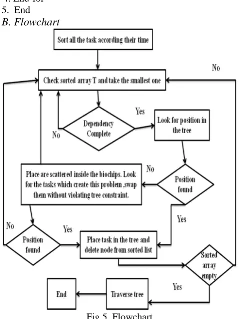
B. Flowchart
Copyright © 2013 IJECCE, All right reserved
V. D
ESCRIPTION WITH AS
AMPLEE
XAMPLELet us consider an input dependency graph as shown in
Fig.6. Task Graph C[t] = null, A[t] = null. And array size is 5*5.
Table:1
T[m] A B C D E F
Time[m] 3 2 1 3 3 2
After sorting the task with respect to Time Table: 2
T[m] C B F A D E
Time[m] 1 2 2 3 3 3
Task C is not dependent to other task and A[t]is empty so make the C as root of T-Tree. Put A[t] ={C}. Delete C from array T. Now B comes and B is not dependent in any other task so, B is schedule at time 0 and B is placed as middle child of task C. Put A[t]={B,C}. Delete B from array. Next come F it can’t be schedule because it dependent on task D and F. Task F is start only after the finish of task D and F. Next come A it can be schedule and is placed as right child of task B.
Put A[t]={A,B,C}. Delete A from array.
Next comes D, it can be scheduled at time 0 but no sufficient space is available in the form of 4×2 or 2×4 so skip it. So interchange the position of task B and task C. Again no space is available in the same form so interchange task C and task A. Next comes E, again it can’t be scheduled due to violation of precedence constraint.
At time 0 A[t] = {C,A,B}.
At time 2 free cell is 21 as B and C are finished at time 2. Put the task B and task C in C[t] = {C, B}.
Table: 3
T[m] F A D E
Time[m] 2 3 3 3
Table: 4
C[t] C B
Scan T[m]at time 2. F & D can’t be scheduled because of precedence constraints. Node E can be placed as left child of B. At time 2 the placement of task in array is look like as shown in figure-5.4. Put E in A[t] = {A, E}. At time 3, A will be finished now remove A from A[t] and place it in C[t] = [C, B, A].
Table: 5
T[m] F D E
Time[m] 2 3 3
Table: 6
C[t] C B A
Scan T[m] at time 3 D can be placed as left child of task A. At time 3 the placement of task in array is look like as shown in figure-5.5. Put D in A[t] = {D, A, E}. At this time no free cell is available in the form of 4×4.
After time 6 , D and A will finished so remove D and E from A[t] and placed it in C[t]=[C, B, A, D, E]
Table: 7
T[m] F
Time[m] 2
Table: 8
C[t] C B A D E
Task F can be placed at time 6 and it can be placed as left child of E. Placement and final T-Tree is shown in figure 11.
Copyright © 2013 IJECCE, All right reserved Fig.11. Placement of tasks in array and corresponding
T-tree after time 5 and final
Table 9: Scheduling of task in the biochips with placement Task Size Start
Time
Completion Time
Co-Ordinates
C 3×2 0 1 (0,0)
E 2×5 2 5 (0,0)
F 4×4 6 9 (0,0)
D 4×2 3 6 (2,0)
B 2×3 0 2 (0,2)
A 2×2 0 3 (2,2)
A. Analysis of Experimental Results
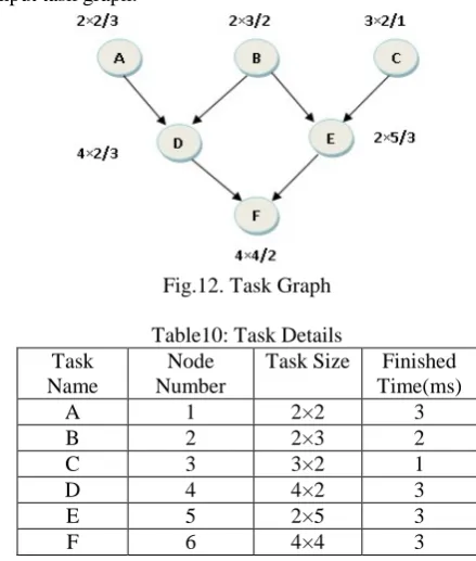
To analyze experimental results we took 6 tasks which have some specified size m×n and finished time. It is given in the fig we took 5×5 array to place the task. Then initially module placement array has only 25 cells to allocate tasks.
Input task
graph:-Fig.12. Task Graph Table10: Task Details Task
Name
Node Number
Task Size Finished Time(ms)
A 1 2×2 3
B 2 2×3 2
C 3 3×2 1
D 4 4×2 3
E 5 2×5 3
F 6 4×4 3
Output of the simulator shown
bellows:-VI. C
ONCLUSIONCopyright © 2013 IJECCE, All right reserved
R
EFERENCES[1] http://www.tutorgig.com/encyclopedia
[2] P.-H. Yuh, C.-L. Yang and Y.-W. Chang. Temporal floorplanning using the t-tree formulation. In Proc. ICCAD, pages 300–305, Nov. 2004
[3] R. B. Fair, V. Srinivasan, H. Ren, P. Paik, V. Pamula, and M. Pollack. Electrowetting-based on-chip sample processing forintegrated microfluidics. In Proc. IEDM, pages 32.5.1–32.5.4, 2003
[4] P.-H. Yuh, C.-L. Yang, Y.-W. Chang and H.-L. Chang.Temporal floorplanning using 3d-subtcg. In Proc. ASPDAC, pages 725– 730, Jan. 2004.
[5] Garey, M.R. AND JOHNSON, G.J:’Computer and intractability’ (W.H.Freeman and Co, 1979)
[6] F.su, s.Ozev and K.Chakrabarty,”Concurrent Testing of Droplet-based Microfluidic systems for Multiplexed Biomedical Assays,”proc.IEEE Int.Test conf., pp.883-892, 2004
[7] Narayan Changder, Debasis Mandal, Samir Roy. A Novel Placement & Scheduling Scheme for Microfluidic Biochips, Proceedings of the All India Seminar on Role of ICT in improving Quality of Life ,pages 48–53,The Institute of Engineers(India), March 26-27,2010. Kolkata, West Bengal, India.
A
UTHOR’
SP
ROFILEMr. Debasis Mandal
Completed M.Tech. Degree in Multimedia & Software System in 2010 from National Institute of Technical Teachers’ Training & Research, Kolkata. Currently working as Assistant Professor in the CSE Department at IMPS College of Engineering & Technology, Malda (West Bengal).
Mr. Rahul Karmakar
Completed M.Tech. Degree in Computer Science & Engineering in 2009 from University of Calcutta, Currently working as Assistant Professor in the CSE Department at IMPS College of Engineering & Technology, Malda (West Bengal).