Information Flow Analysis of
Combined Simulink/Stateflow Models
ITC 2/48Journal of Information Technology and Control
Vol. 48 / No. 2 / 2019 pp. 299-315
DOI 10.5755/j01.itc.48.2.21759
Information Flow Analysis of Combined Simulink/Stateflow Models
Received 2018/10/06 Accepted after revision 2019/03/27
http://dx.doi.org/10.5755/j01.itc.48.2.21759
Corresponding author: marcus.mikulcak@tu-berlin.de
Marcus Mikulcak, Thomas Göthel, Sabine Glesner
Technische Universität Berlin, Software and Embedded Systems Engineering Group Ernst-Reuter-Platz 7, 10587 Berlin, Germany, e-mail: {marcus.mikulcak, thomas.goethel, sabine.glesner}@tu-berlin.de
Paula Herber
University of Münster, AG Embedded Systems Einsteinstraße 62, 48149 Münster, Germany e-mail: paula.herber@uni-muenster.de
Simulink and its state machine design toolbox Stateflow are widely-used industrial tools for the development of complex embedded systems. Due to the strongly differing execution semantics of Simulink and Stateflow, the analysis of combined models poses a difficult challenge, especially when considering their timing behavior. In this paper, we present a novel approach to relate the semantics of both the dynamic Simulink components and the Stateflow controller and use it to perform an information flow analysis on combined models. The key idea of our approach is that we analyze the information flow in a given model by computing an over-approximation of the control flow through the Simulink components, and deduce whether all control flow conditions combined per-mit information to flow on a given path or not. The main contributions of our control flow analysis approach are: (1) we identify timed path conditions which capture the conditions for time-dependent information flow on paths of interest for (discrete) Simulink components, and translate them into a UPPAAL timed automata representa-tion, (2) we translate the Stateflow components to UPPAAL timed automata, and (3) we perform model checking on the translated set of automata in order to analyze the existence of paths in the combined model. With our ap-proach, we safely rule out the existence of information flow on specific paths through a model, which enables us to reason about non-interference between model parts and the compliance with security policies. Furthermore, our approach presents a starting point to generate feasible, efficient test cases and to perform compositional ver-ification. We demonstrate the applicability of our approach using two versions of a complex case study from the automotive domain consisting of multiple safety-critical components communicating over a shared bus system. For this example, an approach based on timed path conditions alone is sound but highly imprecise compared to our combined approach.
Information Technology and Control 2019/2/48
300
1. Introduction
In the area of safety-critical embedded software, such as in the automotive and aerospace domains, pro-gram- ming errors can lead to disastrous and often fatal accidents. At the same time, the complexity of such systems has increased dramatically over recent years. To cope with the steadily increasing complex-ity, current design processes rely more and more on models. One of the most widely-used tools for mod-el-based design is Simulink [28] by MathWorks, which supports the graphical design and simulation of time-continuous as well as time-discrete systems using block diagrams. To additionally support the de-sign of state machine-based embedded controllers in conjunction with these dynamical systems, Stateflow [30], an extension to Simulink, is widely used in in-dustrial design processes. Simulink and Stateflow are very well-suited to grasp the structure of a design on high abstraction levels and to visualize its behavior by simulation.
However, due to the complexity and the dynamic, time-dependent character of the developed models, the analysis of a given combined model is a difficult challenge, in particular if timing aspects are consid-ered. At the same time, combining knowledge about the existence of paths, the conditions under which they are executed, and how an embedded Stateflow controller influences their behavior is a hitherto un-solved problem. This is due to the strongly heteroge-neous semantics of Simulink and Stateflow.
In this paper, we present an approach for an informa-tion flow analysis (IFA) of combined discrete Sim-ulink/Stateflow models. Our approach is threefold: First, we extract timed path conditions from dis-cretely- timed signal-flow components developed in Simulink and prepare them for analysis by converting them into timed automata. Second, we generate U P-PAAL timed automata from the embedded Stateflow controllers. Third, we use model checking to analyze whether the timed path conditions that are extract-ed from Simulink components are satisfiable by the timed automata representation of Stateflow compo-nents. If the conditions are satisfiable, the condition-ally executed paths under analysis potenticondition-ally exist in the combined model, i. e., information flow is possible. If not, they are identified as infeasible and will never be executed in the model, i. e., the absence of
informa-tion flow is guaranteed. All three steps are performed fully automatically, including the generation of the verification goals for model checking.
If our analysis is applied to all possible paths of a giv-en combined model, we can idgiv-entify non-interfergiv-ence between model parts and, thus, reason about compli-ance with security policies. For example, we can veri-fy integrity by checking that no information flow is pos-sible from a non-critical to a critical component. The relevance of such integrity properties was demon-strated, for example, by the Jeep hack in [20], where the attackers gained control over the (safety-critical) speed control and braking system of a Jeep Cherokee through a vulnerability of the (non-critical) infotain-ment system.
We demonstrate the applicability of our approach by, among others, checking the absence of information flow from a (non-critical) odometer to a (safety-crit-ical) braking system in multiple versions of a case study provided by our industrial partners from the automotive domain.
Note that this paper is an extended version of our work published in [17]. In this paper, we provide (1) a more exhaustive discussion of preliminaries with a spe-cial focus in information flow analysis and MATLAB Stateflow in Section 2; (2) a detailed explanation of our previously published approach to extract timed path conditions from the Simulink components of a combined Simulink/Stateflow model in Section 4; (3) an extended case study in Section 7.
The rest of this paper is structured as follows: In Section 2, we briefly introduce the necessary pre-liminaries. In Section 3, we present the main con-tribution of this paper, namely an approach for the analysis of information flow through combined Sim-ulink/Stateflow models. In Sections 4 to 6, we give a detailed description of each step of our approach. We present our evaluation and results in Section 7. Then, we discuss related work in Section 8 and con-clude in Section 9.
2. Preliminaries
Figure 1
Stateflow example 2.1. Information Flow Analysis
The protection of confidentiality and integrity of in-formation inside a software system is an increasingly important problem in the areas of general computing as well as embedded systems. Protecting not only the data itself but also the integrity of the functionality that produces and handles data is a goal of software non-interference policies [5]. Such policies, based on the assignment of security levels to data elements, describe rules between which levels information flow is allowed or forbidden [26]. When aiming at assuring confidentiality, data is prohibited to flow to inappro-priate locations, while in the context of integrity, data is prohibited to flow from inappropriate sources. As non-interference refers to the absence of information flow, it ensures both confidentiality and integrity. 2.2. Path Conditions
In general, path conditions [12] describe sufficient con-ditions for information paths through code or models to be executed. In [6, 7], path conditions are used to capture all paths where information might flow from a source to a target. In contrast to static analyses, which consider all syntactically possible dependencies, path conditions take data and control flow conditions into account. Thus, they exclude, for example, information flow that depends on disjoint control flow conditions. A path condition-based analysis is therefore more precise than classical static analyses.
2.3. Simulink
Simulink [28] is an add-on to the MATLAB IDE by MathWorks that enables graphical modeling and sim-ulation of reactive systems. In its signal-flow orient-ed notation [13, 23], Simulink employs blocks which are connected using signals. Additionally, each block and signal is assigned a set of parameters. Simulation of Simulink models is performed using solvers which compute the output of each block according to its se-mantics. Variable step solvers aim at automatically finding a simulation step size for each block in the model to achieve a level of precision set by the mod-el devmod-eloper. Fixed step solvers use a fixed simulation step size at the expense of precision while increasing performance. The former class of solvers is common-ly used for hybrid or purecommon-ly time-continuous systems, while the latter is used for time-discrete models. In
such models, each block is interpreted as producing a piecewise-constant signal over the simulation time scale, which forms the basis for an automatic transla-tion of the model functransla-tionality and timing behavior to code [31, 14].
2.4. Stateflow
Stateflow [30] is a further add-on to the MATLAB IDE, specifically to Simulink, and gives the designer the possibility to integrate decision logic based on state machines and flow charts into a Simulink mod-el. Stateflow makes use of complex modeling styles incorporating multiple states, event and transition types as well as an execution semantics not only de-pendent on the structure and annotations of the mod-el but also on its layout. Internally, the execution of Stateflow charts is controlled via an event queue into which all implicit events, such as updates to input sig-nals and transitions as well as all explicit events are or-dered and evaluated in a first in, first out (FIFO) fash-ion, i. e., the execution semantics is purely sequential. To give an impression of the Stateflow semantics, we briefly summarize its main building blocks, i. e., states, events, and transitions. Stateflow additionally sup-ports junctions as well as temporal logic operators to model timed conditions.
2.4.1. States
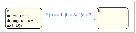
States form the basic building block of the controller logic implemented in Stateflow. An example is shown in Figure 1. If the execution enters a state, a set of actions modeled by the designer takes place, such as the modification of output signals of the automaton or the triggering of events. The action type, entry, during or exit, determines when these actions are performed. Depending on the type, the timing behav-ior and the frequency of the modifications and triggers changes. While the sets of entry and exit actions occur only once every time the state is active, the during actions are performed with every
simula-Figure 1. Stateflow example
set by the model developer.
Fixed step
solvers use a fixed simulation step size at the expense of precision while
increasing performance. The former class of solvers is commonly used for hybrid or purely time-continuous
systems, while the latter is used for time-discrete models. In such models, each block is interpreted as producing a
piecewise-constant signal over the simulation time scale, which forms the basis for an automatic translation of the
model functionality and timing behavior to code [31, 14].
2.4.
Stateflow
Stateflow [30] is a further add-on to the M
ATLABIDE, specifically to Simulink, and gives the designer the
possibility to integrate decision logic based on state machines and flow charts into a Simulink model. Stateflow
makes use of complex modeling styles incorporating multiple states, event and transition types as well as an
execution semantics not only dependent on the structure and annotations of the model but also on its layout.
Internally, the execution of Stateflow charts is controlled via an
event queue
into which all implicit events, such as
updates to input signals and transitions as well as all explicit events are ordered and evaluated in a first in, first out
(FIFO) fashion, i. e., the execution semantics is purely sequential. To give an impression of the Stateflow semantics,
we briefly summarize its main building blocks, i. e., states, events, and transitions. Stateflow additionally supports
junctions as well as temporal logic operators to model timed conditions.
2.4.1.
States
States form the basic building block of the controller logic implemented in Stateflow. An example is shown
in Figure 1. If the execution enters a state, a set of
actions
modeled by the designer takes place, such as the
modification of output signals of the automaton or the triggering of
events
. The
action type
,
entry
,
during
or
exit
, determines
when
these actions are performed. Depending on the type, the timing behavior and the
frequency of the modifications and triggers changes. While the sets of
entry
and
exit
actions occur only once
every time the state is active, the
during
actions are performed with every simulation step and are therefore
dependent on the selected solver of the Simulink and Stateflow model. As shown in Figure 1, actions can
trigger
events
. To manage the complexity of Stateflow automata, it is possible to model hierarchical states by
using
superstates
and
substates
. If a superstate is triggered, its substates are either executed in an exclusive or a
parallel fashion, depending on the modeling style chosen by the developer. While in an exclusive composition, only
one of the mutually exclusive substates can be active at a time, multiple parallel states can be active simultaneously
in a parallel composition. However, as the execution of parallel states is sequential during simulation, an ordering
is imposed either explicitly via annotations made by the designer or implicitly via the relative location of the states.
2.4.2.
Events
Events in Stateflow are a form of trigger mechanism for the execution of states and transitions. As seen in Figure 1,
the
exit
action of state
A
triggers the
explicit
event
D()
. Whenever an event is triggered, it is broadcast to the
parallel states of the current Stateflow chart.
2.4.3.
Transitions
To design the state change logic of a controller, Stateflow states are connected via
transitions
. Similar to states, it
is possible to add guards, trigger events, and actions to transitions. Figure 1 shows an example transition containing
all three mentioned semantical elements. Event
E
triggers the evaluation of the guard condition
a == 1
. As soon
as this condition evaluates to
true
, the corresponding
guard action
b = 3
is executed. Finally, when the transition
is taken, the
transition action
c = 2
is executed and state
B
is marked active.
2.5. U
PPAALTimed Automata
Information Technology and Control 2019/2/48
302
tion step and are therefore dependent on the selected solver of the Simulink and Stateflow model. As shown in Figure 1, actions can trigger events. To manage the complexity of Stateflow automata, it is possible to model hierarchical states by using superstates and substates. If a superstate is triggered, its substates are either executed in an exclusive or a parallel fashion, depending on the modeling style chosen by the devel-oper. While in an exclusive composition, only one of the mutually exclusive substates can be active at a time, multiple parallel states can be active simultaneously in a parallel composition. However, as the execution of parallel states is sequential during simulation, an ordering is imposed either explicitly via annotations made by the designer or implicitly via the relative loca-tion of the states.
2.4.2. Events
Events in Stateflow are a form of trigger mechanism for the execution of states and transitions. As seen in Figure 1, the exit action of state A triggers the ex-plicit event D(). Whenever an event is triggered, it is broadcast to the parallel states of the current Stateflow chart.
2.4.3. Transitions
To design the state change logic of a controller, Stateflow states are connected via transitions. Simi-lar to states, it is possible to add guards, trigger events, and actions to transitions. Figure 1 shows an example transition containing all three mentioned semantical elements. Event E triggers the evaluation of the guard condition a == 1. As soon as this condition evaluates to true, the corresponding guard action b = 3 is exe-cuted. Finally, when the transition is taken, the tran-sition action c = 2 is executed and state B is marked active.
2.5. UPPAAL Timed Automata
Timed automata (TA) [1] are a timed extension of the classical finite state automata. A notion of time is in-troduced by clock variables, which are used in clock constraints to model time-dependent behavior. Sys-tems comprising multiple concurrent processes are modeled by networks of TA, which are executed with interleaving semantics and synchronize on channels. UPPAAL [3, 4] is a tool suite for modeling, simulation, animation, and verification of networks of timed
automata. The UPPAAL modeling language extends timed automata by bounded integer variables, binary and broadcast channels, and urgent and committed locations. A small example UPPAAL timed automaton is shown in Figure 2. The initial location is denoted by . The label request? denotes receiving on the channel request, while ack! denotes sending on channel ack. The clock variable x is first set to 0 and then used in two clock conditions: the invariant x <= maxtime denotes that the corresponding location must be left before x becomes greater than maxtime, and the guard x >= mintime enables the corre-sponding edge if x is greater or equal mintime. The symbol depicts an urgent location and the symbol a committed location. Urgent and committed loca-tions are used to model localoca-tions where no time may pass. Leaving a committed location has priority over leaving non-committed locations.
The UPPAAL model checker enables fully-automatic verification of (unnested) Computation Tree Logic (CTL) formulae on a given network of timed automata.
3. Information Flow Analysis of
Simulink/Stateflow Models
The heterogeneous nature of software models con-taining both Simulink and Stateflow parts makes their analysis hard. The main challenge is to reconcile the inherently different semantics of Simulink and Stateflow, and in particular their timing.
The semantics of Simulink is defined by the simu-lation semantics of the solver, where the function-ality and timing depend on the simulation step size. The semantics of Stateflow is defined by evalua-Figure 2
UPPAAL example
◦
Figure 2. UPPAAL example
UPPAAL [3, 4] is a tool suite for modeling, simulation, animation, and verification of networks of timed
automata. The UPPAAL modeling language extends timed automata by bounded integer variables, binary and
broadcast channels, and urgent and committed locations. A small example UPPAAL timed automaton is shown
in Figure 2. The initial location is denoted by . The label request? denotes receiving on the channel request, while ack! denotes sending on channel ack. The clock variable x is first set to 0 and then used in two clock conditions: the invariant x <= maxtime denotes that the corresponding location must be left before x becomes greater than maxtime, and the guard x >= mintime enables the corresponding edge if x is greater or equal mintime. The symbol depicts an urgent location and the symbol a committed location. Urgent and committed locations are used to model locations where no time may pass. Leaving a committed location has priority over leaving non-committed locations.
The UPPAAL model checker enables fully-automatic verification of (unnested) Computation Tree Logic (CTL)
formulae on a given network of timed automata.
3. Information Flow Analysis of Simulink/Stateflow Models
The heterogeneous nature of software models containing both Simulink and Stateflow parts makes their analysis hard. The main challenge is to reconcile the inherently different semantics of Simulink and Stateflow, and in particular their timing.
The semantics of Simulink is defined by the simulation semantics of the solver, where the functionality and timing depend on the simulation step size. The semantics of Stateflow is defined by evaluation rules that determine which transition fires in each step, whereby a step is made whenever one of the input signals is reevaluated, i. e., every simulation time step ts. The main idea of our approach for the analysis of the information flow in combined, discrete Simulink/Stateflow models is to relate a Stateflow controller with its surrounding Simulink model using timed automata in order to enable model checking. For the analysis of information flow in pure Simulink components, we make use of our approach previously presented in [18]. There, we compute timed path conditions for a given Simulink model by performing a backwards analysis through the model. The timed path conditions extracted using our approach describe sufficient conditions for the execution of a given path, i. e., they provide a sound over-approximation of the possible information flow. For Stateflow, we utilize an approach that translates Stateflow components to a system of UPPAAL timed automata [11, 34]. With that, the semantics
of a Stateflow component is precisely defined. We make use of this approach to gain a formally well-defined representation of the Stateflow components in a combined Simulink/Stateflow model, and to gain access to the UPPAAL tool suite, including the UPPAAL model checker.
To relate the timed path conditions resulting from [18] for Simulink components with the UPPAAL timed
automata representation of Stateflow components, we assume that a Stateflow controller is embedded into a Simulink model and has an effect on some of its components by controlling the execution of paths through the surrounding Simulink components. Our approach to analyze the information flow in combined Simulink/Stateflow models, shown in Figure 4, is threefold:
(1) We utilize our algorithm shown in [18, 19] to extract timed path conditions for all paths between a set of model elements of interest from the Simulink model (see step (1.a) in Figure 4). Along these paths, the conditions for information flow as well as their timing are gathered and expressed as sets of timed path conditions CTP.
To make this representation compatible with the UPPAAL timed automata representation of the Stateflow
semantics presented in [19], we propose a timed automata representation of these timed path conditions and generate one automaton for each set in CTP (1.b). As we extract timed path conditions for all paths
tion rules that determine which transition fires in each step, whereby a step is made whenever one of the input signals is reevaluated, i. e., every simula-tion time step ts. The main idea of our approach for the analysis of the information flow in combined, discrete Simulink/Stateflow models is to relate a Stateflow controller with its surrounding Simulink model using timed automata in order to enable mod-el checking. For the analysis of information flow in pure Simulink components, we make use of our approach previously presented in [18]. There, we compute timed path conditions for a given Simulink model by performing a backwards analysis through the model. The timed path conditions extracted using our approach describe sufficient conditions for the execution of a given path, i. e., they provide a sound over-approximation of the possible infor-mation flow. For Stateflow, we utilize an approach that translates Stateflow components to a system of UPPAAL timed automata [11, 34]. With that, the se-mantics of a Stateflow component is precisely de-fined. We make use of this approach to gain a for-mally well-defined representation of the Stateflow components in a combined Simulink/Stateflow model, and to gain access to the UPPAAL tool suite, including the UPPAAL model checker.
To relate the timed path conditions resulting from [18] for Simulink components with the UPPAAL timed au-tomata representation of Stateflow components, we assume that a Stateflow controller is embedded into a Simulink model and has an effect on some of its com-ponents by controlling the execution of paths through the surrounding Simulink components. Our approach to analyze the information flow in combined Simulink/ Stateflow models, shown in Figure 4, is threefold:
1 We utilize our algorithm shown in [18, 19] to extract
timed path conditions for all paths between a set of model elements of interest from the Simulink mod-el (see step (1.a) in Figure 4). Along these paths, the conditions for information flow as well as their timing are gathered and expressed as sets of timed path conditions CTP. To make this representation
compatible with the UPPAAL timed automata rep-resentation of the Stateflow semantics presented in [19], we propose a timed automata representa-tion of these timed path condirepresenta-tions and generate one automaton for each set in CTP (1.b). As we
ex-tract timed path conditions for all paths between
model elements of interest and, on these paths, ex-tract all control flow conditions, we achieve a sound over-approximation of the possible information flow through the Simulink model.
2 We adapt the method presented in [11, 34] to
trans-late embedded Stateflow components to a system of UPPAAL timed automata (2.a). We are confident that their translation is sound, as it provides a di-rect mapping of each Stateflow process into a se-mantically equivalent timed automata representa-tion, and explicitly models the execution semantics of Stateflow, including the event queue. We extend the resulting system with an automaton that pro-vides arbitrary input signals (2.b). This enables a sound and comprehensive analysis of the behavior of the Stateflow controller, as we simulate the com-plete environment, i. e., all possible combinations of input signals to the controller.
3 We use the information gathered in the previous
steps to automatically generate reachability prop-erties for the UPPAAL model checker (3.a) and start the checking process (3.b). In this final step, we ef-fectively utilize model checking to analyze wheth-er the timed path conditions dwheth-erived from Sim-ulink can be satisfied by the Stateflow controller, i. e., if one or multiple of the timed path conditions expressed in CTP hold on the translated model of the
Stateflow controller SFM. If they do not hold, then we have safely shown that information flow over the paths under analysis is impossible as the path is never executed in the Simulink models and that the property of non-interference holds.
Information Technology and Control 2019/2/48
304
size ts. This relation between the discretely-timed solver of the Simulink model and the evaluation of the Stateflow automaton makes it possible to relate both semantics.
In the remainder of this section, we first introduce a motivating example for our approach in Section 3.1. Then, we introduce the assumptions we impose on the models that our approach is able to analyze in Sec-tion 3.2. In SecSec-tion 4, we provide an overview of our approach to extract timed path conditions from the signal-flow oriented Simulink components of com-bined Simulink/Stateflow models. Subsequently, we present our approach to prepare these extracted sets of timed path conditions for model checking by con-verting them into UPPAAL timed automata in Section 4.1. We then present the generation of networks of U P-PAAL timed automata from the Stateflow components of the models as well as our generalization to support arbitrary inputs during the model checking process in Section 5. Finally, we present our automatic gen-eration of properties using the previously extracted information and the initiation of the model checking process by our algorithm as well as the evaluation of its results in Section 6.
3.1. Motivating Example
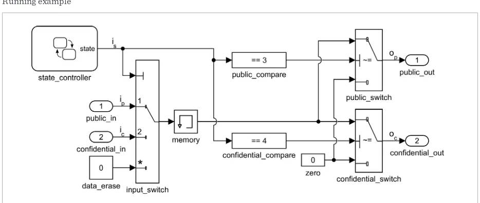
To illustrate our approach, we use a shared communi-cation infrastructure , such as commonly found in the
design of automotive software, as a running example. Figure 3 shows the corresponding Simulink model. It uses a Memory block as internal buffer and switches to route the incoming and outgoing data according to their source and target, respectively. Information of two different security levels (from the public input ipand confidential input ic) is fed into the shared buf-fer. According to the current operation mode set by a controller implemented in Stateflow, confidential or public information is saved in the buffer and passed to the corresponding output. Although confidential and public data share the same memory block as buffer, the routing conditions are intended to ensure that confi-dential input data can never flow to the public output. To this end, the operation mode defines which input should be routed to the output. The designer did, how-ever, not take the timing behavior of the Memory block into account. When examining the timing, we discover that if the operation mode switches from confidential to public, the buffer content that is passed to the out-puts still holds the confidential data for one time unit, i. e., the confidential contents are sent to the public output. The timed path conditions for the Simulink part of this example correctly show that information flow is indeed possible from icto op, as shown in [18]. However, as the Stateflow controller is responsible for the modification of the system state is, an analysis of its behavior in conjunction with the timed path con-ditions is necessary to evaluate whether the combined
Figure 3 Running example
Figure 3. Running example
(2) We adapt the method presented in [11, 34] to translate embedded Stateflow components to a system of UPPAAL
timed automata (2.a). We are confident that their translation is sound, as it provides a direct mapping of each Stateflow process into a semantically equivalent timed automata representation, and explicitly models the execution semantics of Stateflow, including the event queue. We extend the resulting system with an automaton that provides arbitrary input signals (2.b). This enables a sound and comprehensive analysis of the behavior of the Stateflow controller, as we simulate the complete environment, i. e., all possible combinations of input signals to the controller.
(3) We use the information gathered in the previous steps to automatically generate reachability properties for the UPPAAL model checker (3.a) and start the checking process (3.b). In this final step, we effectively utilize
model checking to analyze whether the timed path conditions derived from Simulink can be satisfied by the Stateflow controller, i. e., if one or multiple of the timed path conditions expressed in CTP hold on the translated
model of the Stateflow controller SFM. If they do not hold, then we have safely shown that information flow
over the paths under analysis is impossible as the path is never executed in the Simulink models and that the property of non-interference holds.
Note that a Stateflow state machine is connected to the surrounding model Simulink model via signals SC
that can be used as variables inside guards. Variables modified in state or transition actions inside Stateflow state machines form their output signals S and are routed to the Simulink model. There, they act as control signals that impose conditions on information flow paths from the inputs I to the outputs O. The evaluation of a Stateflow automaton is performed whenever one of the input signals to the automaton is reevaluated by the solver. Then, its state is reevaluated and a one of the possible transitions is taken. We can therefore define a minimal time interval between every change in the output of a Stateflow automaton. Under the assumption of a uniform sample time throughout the model, it is equal to the simulation step size ts. This relation between the
discretely-timed solver of the Simulink model and the evaluation of the Stateflow automaton makes it possible to relate both semantics.
In the remainder of this section, we first introduce a motivating example for our approach in Section 3.1. Then, we introduce the assumptions we impose on the models that our approach is able to analyze in Section 3.2. In Section 4, we provide an overview of our approach to extract timed path conditions from the signal-flow oriented Simulink components of combined Simulink/Stateflow models. Subsequently, we present our approach to prepare these extracted sets of timed path conditions for model checking by converting them into UPPAAL
timed automata in Section 4.1. We then present the generation of networks of UPPAAL timed automata from the
Stateflow components of the models as well as our generalization to support arbitrary inputs during the model checking process in Section 5. Finally, we present our automatic generation of properties using the previously extracted information and the initiation of the model checking process by our algorithm as well as the evaluation of its results in Section 6.
3.1. Motivating Example
Figure 4 Overall approach Simulink/Stateflow model suffers from the same
se-curity policy violation. 3.2. Assumptions
Our information flow analysis approach supports dis-crete Simulink/Stateflow models that satisfy the fol-lowing assumptions:
1 Only time-discrete, fixed-step solvers are used [18], 2 a uniform sample time is used,
3 no algebraic loops are used,
4 control signals do not depend on any feedback
loops.
All discrete Simulink/Stateflow models that satisfy these assumptions can be safely analyzed using our approach. Note that as we analyze the control flow of Simulink subsystems, we do not impose any re-strictions on the data paths, i. e., complex modeling elements like integrators and transfer functions, to-gether with arbitrary feedback loops, may be used on the data path. Note also that the existing translation mechanism for Stateflow described in [11, 34] does not impose any additional restrictions, as a full trans-lation of all Stateflow features is provided.
Our restriction to purely discrete models is accept-able, as we target safety-critical embedded software systems, which typically do not contain any contin-uous components. The restriction to a uniform sam-ple time is mainly for simplicity of presentation and could be relaxed. Support for algebraic loops would require to incorporate a fixed-point analysis into our approach and as they are not present in the case stud-ies provided by our industrial partners, we left this open for future work. The restriction on control sig-nals (4) is the most serious restriction and we hope to relax it in the near future by providing a more sophis-ticated analysis of the control flow in a given Simulink model. However, this assumption was also met by the case studies provided by our industrial partners.
4. Extracting Timed Path Conditions
from Simulink Components
In this section, we provide an overview of the first steps (see (1.a) and (1.b) of Figure 4) of our infor-mation flow analysis approach, in which we use the
algorithm we have previously published in [18] to generate timed path conditions from the dynamic signal-flow (i. e., Simulink) components of the mod-el, and translate them into a UPPAAL timed automa-ton representation.
Figure 4. Overall approach
Memory block as internal buffer and switches to route the incoming and outgoing data according to their source and target, respectively. Information of two different security levels (from the public input ipand confidential input ic) is fed into the shared buffer. According to the current operation mode set by a controller implemented in Stateflow, confidential or public information is saved in the buffer and passed to the corresponding output. Although confidential and public data share the same memory block as buffer, the routing conditions are intended to ensure that confidential input data can never flow to the public output. To this end, the operation mode defines which input should be routed to the output. The designer did, however, not take the timing behavior of the Memory block into account. When examining the timing, we discover that if the operation mode switches from confidential to public, the buffer content that is passed to the outputs still holds the confidential data for one time unit, i. e., the confidential contents are sent to the public output. The timed path conditions for the Simulink part of this example correctly show that information flow is indeed possible from icto op, as shown in [18]. However, as the Stateflow controller is responsible for the modification of the system state is, an analysis of its behavior in conjunction with the timed path conditions is necessary to evaluate whether the combined Simulink/Stateflow model suffers from the same security policy violation.
3.2. Assumptions
Our information flow analysis approach supports discrete Simulink/Stateflow models that satisfy the following assumptions:
(1) Only time-discrete, fixed-step solvers are used [18], (2) a uniform sample time is used,
(3) no algebraic loops are used,
(4) control signals do not depend on any feedback loops.
All discrete Simulink/Stateflow models that satisfy these assumptions can be safely analyzed using our approach. Note that as we analyze the control flow of Simulink subsystems, we do not impose any restrictions on the data
For the computation of timed path conditions from the Simulink components of a combined system, we use a two-step approach: (1) Statically identify all paths in a given Simulink model and collect all path conditions on each path. (2) For each path, propagate all local control flow conditions backwards through the model in order to compute timed path conditions that solely depend on input variables.
Using this approach, it is possible to express condi-tions on paths through Simulink models containing time- dependent elements. In general, for a single path, these conditions take the following form shown in Equation (1):
(a)Timed path condition UPPAAL template (b) Initial location UPPAAL template (c) Observer automaton for Equation (2)
Figure 5. Observer automata
paths, i. e., complex modeling elements like integrators and transfer functions, together with arbitrary feedback loops, may be used on the data path. Note also that the existing translation mechanism for Stateflow described in [11, 34] does not impose any additional restrictions, as a full translation of all Stateflow features is provided.
Our restriction to purely discrete models is acceptable, as we target safety-critical embedded software systems, which typically do not contain any continuous components. The restriction to a uniform sample time is mainly for simplicity of presentation and could be relaxed. Support for algebraic loops would require to incorporate a fixed-point analysis into our approach and as they are not present in the case studies provided by our industrial partners, we left this open for future work. The restriction on control signals (4) is the most serious restriction and we hope to relax it in the near future by providing a more sophisticated analysis of the control flow in a given Simulink model. However, this assumption was also met by the case studies provided by our industrial partners.
4. Extracting Timed Path Conditions from Simulink Components
In this section, we provide an overview of the first steps (see (1.a) and (1.b) of Figure 4) of our information flow analysis approach, in which we use the algorithm we have previously published in [18] to generate timed path conditions from the dynamic signal-flow (i. e., Simulink) components of the model, and translate them into a UPPAAL timed automaton representation.
For the computation of timed path conditions from the Simulink components of a combined system, we use a two-step approach: (1) Statically identify all paths in a given Simulink model and collect all path conditions on each path. (2) For each path, propagate all local control flow conditions backwards through the model in order to compute timed path conditions that solely depend on input variables.
Using this approach, it is possible to express conditions on paths through Simulink models containing time- dependent elements. In general, for a single path, these conditions take the following form shown in Equation (1):
TP
=0 =1
( ) = T n ( )j t l ts
l j
c i→o p s − ⋅
∧∧
(1)with{ ,i I o O s S∈ ∈ , j∈ }.
There, T denotes the depth of the path under analysis in time slices [18], s1,...,sn denote all control
signals,and ts denotes the simulation step size. Each path condition p s( )j corresponds to a conjunction of the atomic control flow conditions that are collected for each control signal in each time slice t l t− ⋅ s on the given path from i to o during the backward analysis. The timed path condition c iTP( →o) defines a sufficient condition for information to flow through the path starting at data input i and leading to the data output o.
From our running example shown in fig:running_example, we are able to extract the following conditions for information to flow from the confidential data input ic to the public data output op:
TP(c p) = ( == 4) ( == 1)s t s t ts
c i →o i ∧i −
(2) (1)
Information Technology and Control 2019/2/48
306
There, T denotes the depth of the path under analy-sis in time slices [18], s1,...,sn denote all control
sig-nals,and ts denotes the simulation step size. Each path condition p s( )j corresponds to a conjunction of
the atomic control flow conditions that are collected for each control signal in each time slice t l t− ⋅ s on the given path from i to o during the backward analysis. The timed path condition c iTP( →o) defines a suffi-cient condition for information to flow through the path starting at data input i and leading to the data output o.
From our running example shown in fig:running_ex-ample, we are able to extract the following conditions for information to flow from the confidential data in-put ic to the public data output op:
(a)Timed path condition UPPAAL template (b) Initial location UPPAAL template (c) Observer automaton for Equation (2)
Figure 5. Observer automata
paths, i. e., complex modeling elements like integrators and transfer functions, together with arbitrary feedback loops, may be used on the data path. Note also that the existing translation mechanism for Stateflow described in [11, 34] does not impose any additional restrictions, as a full translation of all Stateflow features is provided.
Our restriction to purely discrete models is acceptable, as we target safety-critical embedded software systems, which typically do not contain any continuous components. The restriction to a uniform sample time is mainly for simplicity of presentation and could be relaxed. Support for algebraic loops would require to incorporate a fixed-point analysis into our approach and as they are not present in the case studies provided by our industrial partners, we left this open for future work. The restriction on control signals (4) is the most serious restriction and we hope to relax it in the near future by providing a more sophisticated analysis of the control flow in a given Simulink model. However, this assumption was also met by the case studies provided by our industrial partners.
4. Extracting Timed Path Conditions from Simulink Components
In this section, we provide an overview of the first steps (see (1.a) and (1.b) of Figure 4) of our information flow analysis approach, in which we use the algorithm we have previously published in [18] to generate timed path conditions from the dynamic signal-flow (i. e., Simulink) components of the model, and translate them into a UPPAAL timed automaton representation.
For the computation of timed path conditions from the Simulink components of a combined system, we use a two-step approach: (1) Statically identify all paths in a given Simulink model and collect all path conditions on each path. (2) For each path, propagate all local control flow conditions backwards through the model in order to compute timed path conditions that solely depend on input variables.
Using this approach, it is possible to express conditions on paths through Simulink models containing time- dependent elements. In general, for a single path, these conditions take the following form shown in Equation (1):
TP
=0 =1
( ) = T n ( )j t l ts
l j
c i→o p s − ⋅
∧∧
(1)with{ ,i I o O s S∈ ∈ , j∈ }.
There, T denotes the depth of the path under analysis in time slices [18], s1,...,sn denote all control
signals,and ts denotes the simulation step size. Each path condition p s( )j corresponds to a conjunction of the
atomic control flow conditions that are collected for each control signal in each time slice t l t− ⋅ s on the given path from i to o during the backward analysis. The timed path condition c iTP( →o) defines a sufficient condition for information to flow through the path starting at data input i and leading to the data output o.
From our running example shown in fig:running_example, we are able to extract the following conditions for information to flow from the confidential data input ic to the public data output op:
TP( ) = ( == 4) ( == 1)
t t
t s
c p s s
c i →o i ∧ i −
(2)
. (2)
4.1. From Timed Path Conditions to Timed Automata
In this step, we present our approach to create com-patibility between the extracted sets of timed path conditions and the Stateflow controllers translated into networks of UPPAAL timed automata. Specifical-ly, our main contribution in this step is the creation of observer automata [22] for the information flow paths under analysis.
The main purpose of our translation from timed path conditions to timed automata is to make our represen-tation of the timed paths in a Simulink model com-patible with the network of UPPAAL timed automata generated from the Stateflow components. The key idea of our translation is to encode the timed path condition into an observer automaton, which ob-serves a timed automata model of a Stateflow compo-nent and checks whether the timed path conditions derived from a Simulink model can be satisfied by the Stateflow component. Note that the timed path condi-tion is satisfiable if the final locacondi-tion of this observer automaton is reachable, which can conveniently be checked using the UPPAAL model checker.
The translation of Stateflow automata to UPPAAL presented in [11, 34] does not utilize clocks. We are therefore forced to rely on a different mechanism to synchronize the automaton to be created with the main system of automata created from the Stateflow model. As shown in the following, we make use of
two variables introduced by the authors of [11, 34] that emulate the simulation time found in Simulink/ Stateflow, both globally (t_total) and inside states (t_driven).
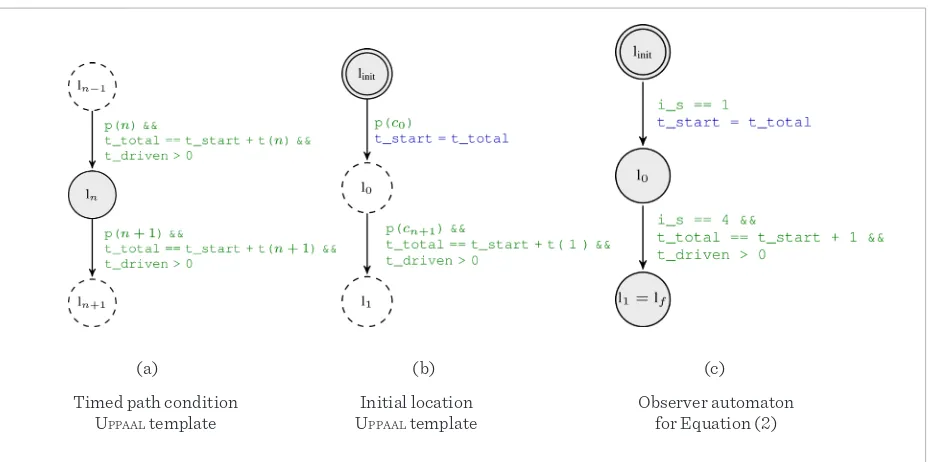
The input to our generation algorithm is a list of timed path conditions, i. e. , the extracted set of timed path conditions cTP for a path under analysis sorted by time slices, as shown in Equation (1). The maximum length of this list is the time slice depth of the current path T. We perform multiple iterations over the list of timed path conditions we receive as an input. First, we add an initial state and one location for every entry in the list. Second, we create all forward transitions between the created locations. Every transition is guarded by the correct valuation of the next entry in the list. Additionally, whenever the first guard is eval-uated to true, an internal variable t_start is set to the current value of the global time variable t_total and is used in all forward transitions to evaluate whether the timing requirement between input list conditions is met. We then add backward transitions from each state back to the initial state. These transitions are taken whenever the timing or control signal require-ment to proceed to the next entry in the set is not met. Further, we add backward transitions from every state back to the state corresponding to the first entry in the list. These transitions are taken whenever the timing and data requirements are not fulfilled to enter the next state in the list but match its first entry. In the next step, we add all required self-loops to the autom-aton. These self-loops are taken whenever the simu-lation time has not progressed far enough for the next forward transition to be taken or whenever the back-ward transition guard cannot be evaluated to true. Finally, the automaton will be added to the translated Stateflow system. We have illustrated our generation algorithm using UPPAAL timed automata templates shown in Figures 5a and 5b. There, dashed states denote placeholders for subsequent iterations of the algorithm during generation and the functions p n( )
and t n( ) extract the nth atomic condition and the n th timing requirement from the input list. Revisiting our running example, the automaton created from the timed path condition c iTP(c→op), shown in Figure
5c. There, we initially wait until is== 1. Whenever
this condition is satisfied, we check whether is == 4
Figure 5
Observer automata
(a)Timed path condition UPPAAL template (b) Initial location UPPAAL template (c) Observer automaton for Equation (2) Figure 5. Observer automata
paths, i. e., complex modeling elements like integrators and transfer functions, together with arbitrary feedback loops, may be used on the data path. Note also that the existing translation mechanism for Stateflow described in [11, 34] does not impose any additional restrictions, as a full translation of all Stateflow features is provided.
Our restriction to purely discrete models is acceptable, as we target safety-critical embedded software systems, which typically do not contain any continuous components. The restriction to a uniform sample time is mainly for simplicity of presentation and could be relaxed. Support for algebraic loops would require to incorporate a fixed-point analysis into our approach and as they are not present in the case studies provided by our industrial partners, we left this open for future work. The restriction on control signals (4) is the most serious restriction and we hope to relax it in the near future by providing a more sophisticated analysis of the control flow in a given Simulink model. However, this assumption was also met by the case studies provided by our industrial partners.
4. Extracting Timed Path Conditions from Simulink Components
In this section, we provide an overview of the first steps (see (1.a) and (1.b) of Figure 4) of our information flow analysis approach, in which we use the algorithm we have previously published in [18] to generate timed path conditions from the dynamic signal-flow (i. e., Simulink) components of the model, and translate them into a UPPAAL timed automaton representation.
For the computation of timed path conditions from the Simulink components of a combined system, we use a two-step approach: (1) Statically identify all paths in a given Simulink model and collect all path conditions on each path. (2) For each path, propagate all local control flow conditions backwards through the model in order to compute timed path conditions that solely depend on input variables.
Using this approach, it is possible to express conditions on paths through Simulink models containing time- dependent elements. In general, for a single path, these conditions take the following form shown in Equation (1):
TP
=0 =1
(
) =
T n( )
j t l ts l jc i
→
o
∧∧
p s
− ⋅ (1)with
{ ,
i I o O s S
∈ ∈
,
j∈
}
.There,
T
denotes the depth of the path under analysis in time slices [18],s
1,...,
s
n denote all control signals,andt
s denotes the simulation step size. Each path conditionp s
( )
j corresponds to a conjunction of the atomic control flow conditions that are collected for each control signal in each time slicet l t
− ⋅
s on the given path fromi
too
during the backward analysis. The timed path conditionc i
TP(
→
o
)
defines a sufficient condition for information to flow through the path starting at data inputi
and leading to the data outputo
.From our running example shown in fig:running_example, we are able to extract the following conditions for information to flow from the confidential data input
i
c to the public data outputo
p:TP
(
) = ( == 4) ( == 1)
t t
t s
c p s s
c i
→
o
i
∧
i
− (2)Timed path condition UPPAAL template
Initial location UPPAAL template
Observer automaton for Equation (2)
(a) (b) (c)
satisfied. If is== 1 is satisfied but is == 4 is not
satis-fied in the next step, we reset the observer automaton. By checking initially whether the timed path condi-tion that refers to the earliest time slice is satisfied, and then subsequently checking whether all timed path conditions referring to the subsequent time steps are satisfied, we ensure that we detect all sequences of outputs of the Stateflow controller which might satis-fy the overall timed path condition, i. e., our approach is sound.
5. Stateflow Controllers as Timed
Automata
In this section, we present our adaption of an exist-ing mechanism to translate Stateflow controllers into networks of UPPAAL timed automata. The translation makes it possible to elevate the analysis of the con-troller behavior into a formally well-defined repre-sentation and enables the usage of the UPPAAL model checker to verify properties on the controller behav-ior. Specifically, we aim at combining the generated observer automata presented in the previous section
with the networks of automata created from the con-troller in order to verify whether the extracted timed path conditions are satisfiable. Our main contribu-tion in this seccontribu-tion is the generalizacontribu-tion of the execu-tion behavior to allow model checking of the controller for arbitrary inputs. We utilize a technique developed in [34] that converts Stateflow automata to UPPAAL timed automata. In the following, we briefly introduce the concepts behind their work and present our adap-tations and extensions.
5.1. State Transformation
Information Technology and Control 2019/2/48
308
5.2. Transition Transformation
For each state, all outgoing transitions are saved in an array sorted by the implicit and explicit transition priority. From this array, the Condition Automaton selects the next transition to be evaluated and taken. 5.3. Time
In Stateflow, time can be modeled absolute or event-based. As an absolute value, time is used by, e.g. after, before, at and every in conjunction with a time unit, e. g., after(2, sec). This absolute form is based on the simulation time of the surrounding Simulink model and can be used to synchronize the timing behavior of the Stateflow controller with that of its environment. The second form utilizes the same keywords but makes use of events inside the Stateflow controller, e. g., every(3, e), which executes the associated action with every third occurrence of the event e. To emulate this behavior in UPPAAL, the au-thors have implemented a virtual event stack as a structured array in UPPAAL. To model the simulation time of the Stateflow controller, the authors do not rely on clocks, but implemented two distinct integer variables: t_total and t_driven. The former im-plements the simulation time of the overall system, while the latter implements simulation time passed inside the current state.
5.4. Generalization to Arbitrary Inputs
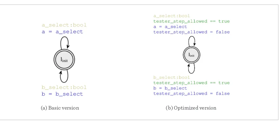
The translation from Stateflow to UPPAAL does not include the possibility to simulate the environment of the Stateflow controller. This means that if, for exam-ple, transitions are guarded by signals driven by the Simulink model the controller is embedded into, their value will be held as uninitialized and will not be part of the verification of the controller. This makes it impos-sible to utilize the translation in its original form, as the signals driving the Stateflow controller are an in-tegral part of its functionality. We therefore extended the translation by a generic tester automaton [25]. A generic tester automaton, in its most basic form, can be seen in Figure 6a. There, a timed automaton with a single state and two edges is shown. On each edge, a Boolean signal, a or b, is set non-deterministically to true or false by using the select syntax built into UPPAAL. This makes it possible to simulate every combination of both signals in every step of the model checking process as the tester automaton runs con-currently to all other automata. Our extension to the original translation analyzes all input signals to the Stateflow controller as well as their data types. Using this information, a tester automaton for the control-ler under analysis is constructed to simulate arbitrary inputs to the controller, thereby acting as the non-de-terministic environment of the controller.
(a) Basic version (b) Optimized version
Figure 6
Generic tester automata
(a) Basic version (b) Optimized version
Figure 6. Generic tester automata
Figure 7. Shared communication infrastructure in a car
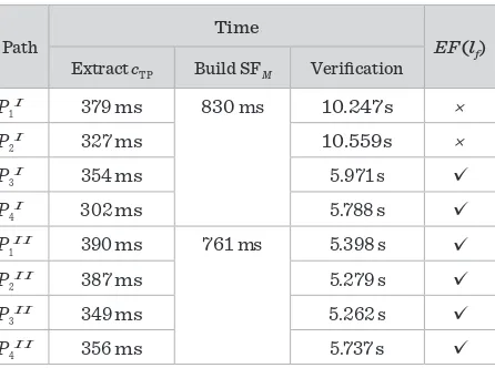
6.1. Generation of Verification Goals
In order for the UPPAAL verifier to check whether the timed path conditions can be satisfied by the generated
system of timed automata, we create appropriate queries. Due to the design of the timed path condition observer automata, we only need to create a single CTL query for each automaton to check reachability of its final location. As seen in Section 4.1, we save information about the final location, therefore, the necessary queries take the form
of exists eventually statements for the existence of a path to the final location lffor every automaton. Hence, the
queries have the form EF (lf) and are generated automatically.
6.2. Model Checking Using UPPAAL
In the final step of our analysis process, the generated queries are verified on the translated UPPAAL timed
automata model which has been extended with one automaton for each set of timed path conditions and a tester automaton to simulate arbitrary inputs. For each entry in the query file, UPPAAL verifies the stated property on the
complete system, i. e., we check whether the timed path conditions can be satisfied by the Stateflow automaton. If so, information is potentially able to flow along the path under analysis. If not, the path does not exist and information flow is therefore shown to be impossible.
7. Evaluation
To evaluate our approach, we have implemented it as an Eclipse plug-in in Java. It utilizes our path
condition extraction algorithm for Simulink [18] and a Stateflow to UPPAAL conversion [11, 34]. 7.1. Case Study
Additionally, we have optimized the behavior of the tester automata in combination with the networks of UPPAAL timed automata. In the basic implementa-tion, the tester automaton selects a new value at every point in the model checking process. However, due to the complex design of the translation from Stateflow to UPPAAL, only a small number of transitions directly relate to transitions taken in the Stateflow controller. We therefore have added a global Boolean variable tester_step_allowed, seen in Figure 6b. It is added to the guards of the edges and consumed as soon as the edge is taken. This flag is raised only when input values to the controller are allowed to change, i. e., with every (emulated) simulation step.
6. Information Flow Analysis Using
U
PPAALIn the final step of our algorithm, we combine the timed automata generated from the sets of timed path conditions in the first step with the translated net-works of timed automata in the previous step. Using information from the first steps, we generate verifica-tion goals for the UPPAAL model checker in order to verify whether the sets of timed path conditions are satisfiable by the translated Stateflow controller. 6.1. Generation of Verification Goals
In order for the UPPAAL verifier to check whether the timed path conditions can be satisfied by the generat-ed system of timgenerat-ed automata, we create appropriate queries. Due to the design of the timed path condition observer automata, we only need to create a single CTL query for each automaton to check reachability of its final location. As seen in Section 4.1, we save informa-tion about the final locainforma-tion, therefore, the necessary queries take the form of exists eventually statements for the existence of a path to the final location lffor ev-ery automaton. Hence, the queries have the form EF (lf) and are generated automatically.
6.2. Model Checking Using UPPAAL
In the final step of our analysis process, the generated queries are verified on the translated UPPAAL timed automata model which has been extended with one automaton for each set of timed path conditions and
a tester automaton to simulate arbitrary inputs. For each entry in the query file, UPPAAL verifies the stat-ed property on the complete system, i. e., we check whether the timed path conditions can be satisfied by the Stateflow automaton. If so, information is poten-tially able to flow along the path under analysis. If not, the path does not exist and information flow is there-fore shown to be impossible.
7. Evaluation
To evaluate our approach, we have implemented it as an Eclipse plug-in in Java. It utilizes our path condition extraction algorithm for Simulink [18] and a Stateflow to UPPAAL conversion [11, 34].
7.1. Case Study
Information Technology and Control 2019/2/48
310
(a) Basic version (b) Optimized version
Figure 6. Generic tester automata
Figure 7. Shared communication infrastructure in a car
6.1. Generation of Verification Goals
In order for the UPPAAL verifier to check whether the timed path conditions can be satisfied by the generated
system of timed automata, we create appropriate queries. Due to the design of the timed path condition observer automata, we only need to create a single CTL query for each automaton to check reachability of its final location. As seen in Section 4.1, we save information about the final location, therefore, the necessary queries take the form of exists eventually statements for the existence of a path to the final location lf for every automaton. Hence, the
queries have the form EF (lf ) and are generated automatically.
6.2. Model Checking Using UPPAAL
In the final step of our analysis process, the generated queries are verified on the translated UPPAAL timed
automata model which has been extended with one automaton for each set of timed path conditions and a tester automaton to simulate arbitrary inputs. For each entry in the query file, UPPAAL verifies the stated property on the
complete system, i. e., we check whether the timed path conditions can be satisfied by the Stateflow automaton. If so, information is potentially able to flow along the path under analysis. If not, the path does not exist and information flow is therefore shown to be impossible.
7. Evaluation
To evaluate our approach, we have implemented it as an Eclipse plug-in in Java. It utilizes our path
condition extraction algorithm for Simulink [18] and a Stateflow to UPPAAL conversion [11, 34].
7.1. Case Study
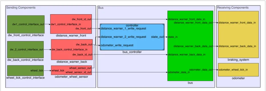
To show the practical applicability of our approach, we have used an industrial case study from the automotive domain. Its core is a communication infrastructure over which two distance warners, supplied by our industrial Figure 7
Shared communication infrastructure in a car
multiple layers of subsystems, making it comparable, in size as well as complexity, to models with similar functionality used by our industrial partners in the automotive domain. Our running example, shown in Section 3.1, shows a simplified version of the routing mechanism and controller utilized in our case study. The main challenge for the analysis of this case study is that the correct routing inherently depends on the timing of the control flow.
Note that we utilize two versions of the bus and the arbitration controller: In the original version, the shared infrastructure can only be used by a single sending component at a time, while in the extend-ed second version, which we have implementextend-ed for demonstration reasons, multiple senders can utilize the shared bus at the same time. In both versions, all three sending components seen on the left in Figure 7 utilize the bus to send their unique id to the receiving components on the right. Inside the channel, a system of switches reacts to the state currently set by the con-troller and routes the data to and from the communi-cation channel accordingly. While in the first version of the case study, the switches that control inputs and outputs to the bus are controlled by the same control signal, they are controlled by two control signals in the second version.
In the following, we present the analysis results for both versions of our case study, i. e., the timed path conditions extracted from the Simulink components of the bus and the controller translated to UPPAAL as well as analysis results and computation times.
7.2. Results
Using our approach, a designer is able to analyze arbitrary paths through the model. For this section, we chose to analyze two paths on which information flow can lead to critical errors in both versions of our case study. To this end, we verify the integrity of the automated braking system by analyzing wheth-er information from the odometwheth-er can evwheth-er reach either input of automated braking system (which should not happen). Additionally, we check wheth-er data sent from the front and back distance war-ners through the bus is able to reach the odometer display (which also should not happen). Note that the former property is crucial to verify that there is no information flow from the non-critical odome-ter to the safety-critical braking system. The latodome-ter property is important as information flow between the distance warner to the odometer may lead to a dropped proximity warning, which in turn may lead to a failure to brake by the automated braking sys-tem. In the following, we present the results of the individual steps taken by our algorithm in order to prove non-interference on the selected paths. 7.2.1. Paths Under Analysis