http: // www.ijrtsm.com© International Journal of Recent Technology Science & Management 20
ISSN : 2455-9679
[Suresh et al. , 4(5), May 2019] Impact Factor : 2.865
IJRTSM
INTERNATIONAL JOURNAL OF RECENT TECHNOLOGY SCIENCE & MANAGEMENT
“DESIGN TEST RIG FOR STOP LOG TESTING”
Suresh Ahirwar
1,
Vikas Sharma
2, Dheeraj Mandliya
31 M.Tech. Scholar, Dept. of Mechanical Engineering, Malwa Institute Of Technology, Indore, MP, India 2-3 Assistant Professor, Dept. of Mechanical Engineering, Malwa Institute Of Technology, Indore, MP, India
ABSTRACT
This paper based on product development project and test them before deploy. This project was assigned by "AECOM Asia Co. Ltd." and purpose is to design and develop a test rig consists of a testing bed, dial gauges for measurement and the mechanism to applied loads specimen. There are two acceptance criteria. One is the maximum residual deflection during loading condition and the other is the maintenance of the elastic behavior. The test can be regarded as pass if both testing criteria are satisfied.
Keyword: FEM, Water force, Stop-Log, Test Rig
I.
I
NTRODUCTIONStoplogs are hydraulic engineering control elements that are used in floodgates to adjust the water level or discharge in a river, canal, or reservoir. Stoplogs are sometimes confused with flashboards, as both elements are used in bulkhead or crest gates. Stoplogs are typically long rectangular timber beams or boards that are placed on top of each other and dropped into premade slots inside
a weir, gate, or channel. Present day, the process of adding and removing stoplogs is not manual, but done with hydraulic stop log lifters and hoists.
Since the height of the barrier can only be adjusted through the addition and removal of stoplogs, finding a lighter and stronger material other than wood or concrete became a more desirable choice. Other materials, including steel and composites, can be used as stoplogs as well. Stoplogs are designed to cut off or stop flow through a conduit.
http: // www.ijrtsm.com© International Journal of Recent Technology Science & Management 21
ISSN : 2455-9679
[Suresh et al. , 4(5), May 2019] Impact Factor : 2.865
Stoplogs are modular in nature, giving the operator of a gated structure the ability to control the water level in a channel
by adding or removing individual stoplogs. A gate may make use of one or more logs. Each log is lowered horizontally
into a space or bay between two grooved piers referred to as a stop log check. In larger gate structures, there will be multiple bays in which stoplogs can be placed to better control the discharge through the structure.
Stoplogs are frequently used to temporarily block flow through a spillway or canal during routine maintenance. At other times stoplogs can be used over longer periods of times, such as when a field is flooded and stoplogs are being used in smaller gates in order to control the depth of water in fields. The logs may be left in and adjusted during the entire time that the field is submerged.
In most cases, the boards used are subjected to high flow conditions. As individual stoplogs begin to age they are
replaced. Typically small amounts of water will leak between individual logs.
II.
OBJCTIVE
The aim of this project is to design and develop a test rig that fulfills AECOM Asia Co. Ltd. Demands. The test rig will be able to perform tests on multiple Logs with full insurance that the results are accurate according to Acceptance Criteria mentioned with test procedures. The project will use a well proven methodology to carry out the product design and development process. This project will be carried out in an efficient way using knowledge acquired at the various expertise that exists at AECOM Asia Co. Ltd. Where new unknown areas are run across, knowledge will be sought and studied until it can be applied to the issue at hand.
The designing and dimensioning of the test rig will be done considering common existing designing rules and guidelines. Also calculations and material analyses will be done accordingly in order to generate a low cost, multifunctional test rig.
The aim is that when the project comes to an end a fully working test rig that satisfies AECOM Asia Co. Ltd. own objectives will be operating in the company‟s test lab.
2.1 Apparatus
The test rack consists of a testing bed, dial gauges for measurement and the applied loads. Test rack for carrying out the test is shown in the attached drawing.
2.2 Test Procedures
2.2.1 Apply the test load progressively over ten steps by hydraulic jacks, recording the load and the reading on the dial gauges. If the log is supported by the seals, the dial gauge readings should be taken simultaneously to negate viscoelastic effect.
2.2.2 Allow the test load to stand for 15 minutes, taking readings every 5 minutes. 2.2.3 Remove the load progressively recording the load and the dial gauge reading.
2.2.4 If the log is tested resting on the seals, the deflection of the log can be calculated by subtracting the end seal deflections from the central deflection.
2.2.5 After the first loading test, the load is removed. The readings of the dial gauges are taken as the reference for the next loading cycle.
2.2.6 Repeat the above test for at least one time.
2.3 Acceptance Criteria
http: // www.ijrtsm.com© International Journal of Recent Technology Science & Management 22
ISSN : 2455-9679
[Suresh et al. , 4(5), May 2019] Impact Factor : 2.865
III.
METHODOLOGYIV.
DESIGN
&
ANALYSIS
OF
TEST
RIG
Client gives specification to make a test rig which can sustain under the load or pressure of water on dam side. To proceed for given specification we will create calculated water load/pressure through hydraulic piston driven electrically and this load is distributed over the span of logs evenly as in actual practice logs will bear on dam side, for this we need to make proper arrangements in betweens logs and hydraulic cylinder. Arrangements are as follows: - Hydraulic Cylinder
- Top Plates
- Horizontal Rib (3 ribs Parallel) - Middle Plates to separates Rib‟s - Load Plates
- Rectangular Pad‟s
As with any type of structure subjected to any kind of external or internal load it is of upmost importance that it does not fail. The failure can occur due to a number of different cases of loads; tension, shearing, creep, fatigue, buckling and more. To cover most of these in a reasonable amount of time it was decided to primarily focus on an overall structural analysis of the rig like equivalent stress analysis and total deformation.
Problem identification
Pre Study
Objective & Needs
Design Validation with CAE
Software
Design Test Rigs
Water Force Calculation
Development of Test Rig
Result of Testing
Deploy on client site
http: // www.ijrtsm.com© International Journal of Recent Technology Science & Management 23
ISSN : 2455-9679
[Suresh et al. , 4(5), May 2019] Impact Factor : 2.865
If the rig should theoretically fail in any of the aspects it will be re-dimensioned until it can handle the loads in a satisfying way. The parts can if failure occurs at the stage of analysis. We can identify and diagnose the failure. A complete functional design of the test rig was created in early chapter from this 3D model which created using Pro-e is further analysis. A finite element method (FEM) application would be needed for the actual analyses. Therefore the 3D model was imported to ANSYS Workbench before any analyses could be performed.
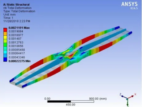
Fig. 4.2: Meshing of Assembly Fig. 4.3: Results for Static structural Analysis for
Total deformation on assembly
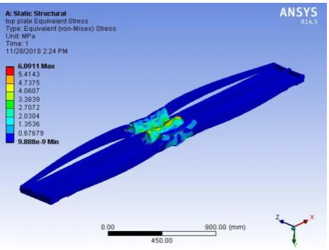
Fig. 4.4: Results for Static structural Analysis for Equivalent Stress on assembly
http: // www.ijrtsm.com© International Journal of Recent Technology Science & Management 24
ISSN : 2455-9679
[Suresh et al. , 4(5), May 2019] Impact Factor : 2.865
The result obtain of the test for Equivalent Stress & total deformation is under the permissible limit for each part, that’s why we can say that design assembly is safe.
Now as on we have checked total deformation and equivalent stress on assembly, side rib’s and Top plate, these are all found safe accordance to company permissible limit, so we could built a physical for testing logs.
V.
RESULTS
While testing of logs on test rig upon the conditions given by the client “COMFORT RICH CO. LTD. HONG KONG” following test results are obtained
Fig. 4.6: Results for Static structural Analysis for Total deformation on assembly
Fig. 4.7: Results for Static structural Analysis for Total deformation on Top Plate
http: // www.ijrtsm.com© International Journal of Recent Technology Science & Management 25
ISSN : 2455-9679
[Suresh et al. , 4(5), May 2019] Impact Factor : 2.865
Table 5.1: Load Test on FRP Log 3500 mm x 400 mm Serviceability Pressure
Bar
Test Load in kN Deflection Loading (Ist) Cycle Deflection Unloading (Ist) Cycle Deflection Loading (IInd) Cycle Deflection Unloading (Ind) Cycle Avg Deflection Loading (mm)
Avg Deflection Unloading (mm)
0 3.63 0.00 0.00 0.00 0.00 0.00 0.00
0.5 8.17 0.80 0.70 0.68 0.71 0.74 0.705
1 12.7 1.10 1.16 1.08 1.15 1.09 1.155
1.5 17.24 1.53 1.67 1.54 1.63 1.535 1.65
2 21.78 2.00 2.10 2.01 2.05 2.005 2.075
2.5 26.32 2.43 2.60 2.40 2.50 2.415 2.55
3 30.85 2.85 2.90 2.90 2.95 2.875 2.925
3.5 35.39 3.29 3.62 3.23 3.37 3.26 3.495
4 39.93 3.72 3.70 3.76 3.70 3.74 3.7
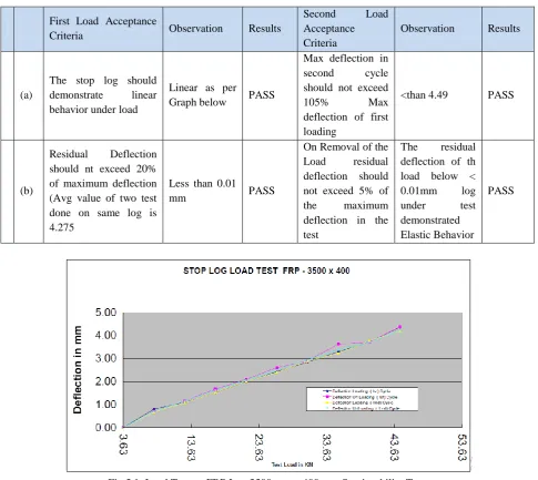
4.5 44.47 4.35 4.38 4.20 4.22 4.275 43
First Load Acceptance
Criteria Observation Results
Second Load
Acceptance Criteria
Observation Results
(a)
The stop log should
demonstrate linear
behavior under load
Linear as per
Graph below PASS
Max deflection in
second cycle
should not exceed
105% Max
deflection of first loading
<than 4.49 PASS
(b)
Residual Deflection
should nt exceed 20% of maximum deflection (Avg value of two test done on same log is 4.275
Less than 0.01
mm PASS
On Removal of the
Load residual
deflection should not exceed 5% of
the maximum
deflection in the test
The residual
deflection of th load below <
0.01mm log
under test
demonstrated Elastic Behavior
PASS Table 5.2: Pass/Fail Report
http: // www.ijrtsm.com© International Journal of Recent Technology Science & Management 26
ISSN : 2455-9679
[Suresh et al. , 4(5), May 2019] Impact Factor : 2.865
VI.
CONCLUSION
&
FUTURE
SCOPE
6.1 Conclusion
This has been a very informative project that has included the entire product development chain from early ideas to the actual manufacturing and testing of the product. Apart from this project has also increased our knowledge in water pressure or force distributes through hydraulic or pneumatics.
In this type of project, where many objectives and restrictions are set up early on, it is likely that some of them will change during the course of the project. This might lead to changes in the concepts and redesign, this is the iterative process that is typical in a product development project.
The result obtain is very satisfactory and tests log properly tested on test rig. Results come through test rig is accurate and client satisfy with it.
6.2 Future Scope
As for the future there are a number of things that can be done to the rig be it improvements or new added parts. When it has been used for a while the lab technicians will get a good view of what they feel is good and what is lacking. In further this test rig can be automatized and frequency of testing logs can be increased.
REFERENCES
1.
Rétfalvi Attila , Michael Stampfer., Szegh Imre “Fixture and Setup Planning and Fixture ConfigurationSystem” Procedia CIRP, Volume 7, Pages 228 – 233, 2013.
2.
Giovanni Moroni, Stefano Petro, Wilma Polini “Robust design of fixture configuration” Procedia CIRP,Volume 21, Pages 189 – 194, 2014.
3.
Zhijun Zhang, Xuwei Sun, Pengyu Du, Jiyu Sun, , Yongfeng Wu “Design of a hydraulically-driven bionicfolding wing” Journal of the Mechanical Behavior of Biomedical Materials,Volume 82, Pages 120–125, 2018.
4.
Jigar D Suthar, K.M .Patel, and Sanjay G Luhana “Design and analysis of fixture for welding an exhaustimpeller” Procedia Engineering, Volume 51, Pages 514 – 519, 2013.
5.
Chetankumar M. Patel, Dr.G.D.Acharya “Design and manufacturing of 8 cylinder hydraulic fixture forboring yoke on VMC – 1050” Procedia Technology, Volume 14, Pages 405-412, 2014.
6.
Wojciech Sochacki, Marta Bold “Damped vibrations of hydraulic cylinder with a spring-damper systemin supports” Procedia Engineering, Volume 177, Pages 41 – 48, 2017.
7.
A. Knobloch, N. Gutha, P. Klingel “Automated Water Balance Calculation for Water DistributionSystems” Procedia Engineering, Volume 89, Pages 428 – 436, 2014.
8.
Ke Yang, Shangjun Guan, Cunlong Wang “The design & calculation for hydraulic cylinder of workpiecehydraulic clamping system of a special CNC machine for guide disc” Procedia Engineering, Volume 16,
Pages 418 – 422, 2011.
9.
Stewart Lowth, Dragos A. Axinte “An assessment of “variation conscious” precision fixturingmethodologiesfor the control of circularity within largemulti-segment annular assemblies” Precision Engineering, Volume 38, Pages 379–390, 2014.
10.
Nino Krznar, Ana Pilipović, Mladen Sercer “Additive manufacturing of fixture for automated 3Dscanning – case study” Procedia Engineering, Volume 149, Pages 197 – 202, 2016.
11.
Hans-Christian Möhring, Petr Wiederkehr, Christoph Lereza, Holger Schmitz, Harald Goldau, Charis Czichy“Sensor Integrated CFRP Structures for Intelligent Fixtures” Procedia Technology, Volume 26, Pages
http: // www.ijrtsm.com© International Journal of Recent Technology Science & Management 27
ISSN : 2455-9679
[Suresh et al. , 4(5), May 2019] Impact Factor : 2.865
12.
T. Papastathis, O. Bakker, S. Ratchev, A. Popov “Design Methodology for Mechatronic Active Fixtureswith Movable Clamps” Procedia CIRP, Volume 3, Pages 323 – 328, 2012.
13.
Pasquale Franciosaa, Salvatore Gerbino, Darek Ceglarek “Fixture Capability Optimisation for Early-stageDesign of Assembly System with Compliant Parts Using Nested Polynomial Chaos Expansion” Procedia
CIRP, Volume 41, Pages 87 – 92, 2016.
14.
Hans-Christian Möhring, Petra Wiederkehr “Intelligent Fixtures for High Performance Machining”Procedia CIRP, Volume 46, Pages 383 – 390, 2016.
15.
Li Hui, Chen Weifang, Shi Shengjie “Design and Application of Flexible Fixture” Procedia CIRP, Volume56 , Pages 528 – 532, 2016.
16.
M. Calabrese, T. Primo, A. Del Prete “Optimization of machining fixture for aeronautical thin-walledcomponents” Procedia CIRP, Volume 60, Pages 32 – 37, 2017.
17.
Abhishek Das, Pasquale Franciosa and Darek Ceglarek “Fixture Design Optimisation ConsideringProduction Batch of Compliant Non-Ideal Sheet Metal Parts” Procedia Manufacturing, Volume 1, Pages
157–168, 2015.
18.
R. Förstmann; J.Wagner; K. Kreisköther; A. Kampker; D. Busch “Design for Automation: The RapidFixture Approach” Procedia Manufacturing, Volume 11, Pages 633 – 640, 2017.
19.
Li, B., Hu, Y., Tang, H., Yu, H. & Hu, H. 2008a. “A comparative study on quality design of fixtureplanning for sheet metal assembly”. Journal of Engineering Design, 19, 1-13.
20.
Li, B., Shiu, B. W. & Lau, K. J. 2001. “Principle and Simulation of Fixture Configuration Design forSheet Metal Assembly with Laser Welding, Part 1: Finite-Element Modelling and a Prediction and
Correction Method”. The International Journal of Advanced Manufacturing Technology, 18, 266-275.
21.
Li, B., Shiu, B. W. & Lau, K. J. 2003. “Robust Fixture Configuration Design for Sheet Metal AssemblyWith Laser Welding”. Journal of Manufacturing Science and Engineering, 125, 120-127.
22.
Li, B., Tang, H., Yang, X. & Wang, H. 2007. “Quality design of fixture planning for sheet metalassembly”. The International Journal of Advanced Manufacturing Technology, 32, 690-697.
23.
Li, B., Yu, H., Yang, X. & Hu, Y. 2010. “Variation Analysis and Robust Fixture Design of a FlexibleFixturing System for Sheet Metal Assembly”. Journal of Manufacturing Science and Engineering, 132,
041014-041014.
24.
Li, Z., Izquierdo, L. E., Kokkolaras, M., Hu, S. J. & Papalambros, P. Y. 2008b. “Multi objectiveOptimization for Integrated Tolerance Allocation and Fixture Layout Design in Multistation
Assembly”. Journal of Manufacturing Science and Engineering, 130, 044501-044501.
25.
Liu, S. C. & Hu, S. J. 1997. “Variation Simulation for Deformable Sheet Metal Assemblies Using FiniteElement Methods”. Journal of Manufacturing Science and Engineering, 119, 368-374.
26.
Lowell, W. F. 1982. Geometrics II: Dimensioning and Tolerancing. ANSI/ASME Standard, Y13.5M,35-52.
27.
Matuszyk, T. I., Cardew-Hall, M. J. & Rolfe, B. F. 2010. “The kernel density estimate/point distributionmodel (KDE-PDM) for statistical shape modeling of automotive stampings and assemblies”. Robotics
and ComputerIntegrated Manufacturing, 26, 370-380.
28.
Menassa, R. J. & Devries, W. R. 1991. “Optimization Methods Applied to Selecting Support Positions inFixture Design”. Journal of Manufacturing Science and Engineering, 113, 412-418.
29.
Phoomboplab, T. & Ceglarek, D. 2008. “Process Yield Improvement Through Optimum Design of FixtureLayouts in 3D Multistation Assembly Systems”. Journal of Manufacturing Science and Engineering, 130,
061005- 061005.
30.
Rearick, M. R., Hu, J. S. & Wu, S. M. “Optimal Fixture Design for Deformable Sheet Metal Workpieces”.Transactions of NARMI/SME, 1993. 407-412.